Page 2296 of 4770

Z18811
Maintenance±Free Battery
Type A
Type B
Blue White Red
OK Charging
NecessaryInsufficient
Water
GREEN EYE DARK EYECLEAR EYE or
CHARGED DISCHARGED ADD WATERLIGHT YELLOW
Z00015
Z00038
DENSOBorroughs
CH0086
CORRECTWRONG CH±2
± CHARGING (5S±FE)CHARGING SYSTEM
1749 Author�: Date�:
HINT:
Check the indicator as shown in the illustration.
4. CHECK BATTERY TERMINALS, FUSIBLE LINK AND
FUSES
(a) Check that the battery terminals are not loose or cor-
roded.
If the terminals are corroded, clean the terminals.
(b) Check the fusible link, H±fuses, M±fuse and fuses for
continuity.
5. INSPECT DRIVE BELTS
(a) Visually check the drive belt for excessive wear, frayed
cords etc.
If any defect has been found, replace the drive belt.
HINT:
Cracks on the rib side of a drive belt are considered acceptable.
If the drive belt has chunks missing from the ribs, it should be
replaced.
(b) Using a belt tension gauge, measure the belt tension.
Belt tension gauge:
DENSO BTG±20 (95506±00020)
Borroughs No. BT±33±73F
Drive belt tension:
w/ A/C New belt
Used belt165 ± 25 lbf
110 ± 10 lbf
w/o A/C New belt
Used belt125 ± 25 lbf
95 ± 20 lbf
If the belt tension is not as specified, adjust it.
HINT:
�ºNew beltº refers to a belt which has been used less than
5 minutes on a running engine.
�ºUsed beltº refers to a belt which has been used on a run-
ning engine for 5 minutes or more.
�After installing a belt, check that it fits properly in the
ribbed grooves.
�Check with your hand to confirm that the belt has not
slipped out of the groove on the bottom of the pulley.
Page 2297 of 4770
CHARGING SYSTEM
CH±3
1750 Author�: Date�: �
After installing a new belt, run the engine for about 5 min")
Z03473
BatteryVoltmeter
Generator Ammeter
Disconnect Wire
from Terminal B
B
± CHARGING (5S±FE)CHARGING SYSTEM
CH±3
1750 Author�: Date�: �
After installing a new belt, run the engine for about 5 min-
utes and recheck the belt tension.
6. VISUALLY CHECK GENERATOR WIRING AND
LISTEN FOR ABNORMAL NOISES
(a) Check that the wiring is in good condition.
(b) Check that there is no abnormal noise from the generator
while the engine is running.
7. CHECK CHARGE WARNING LIGHT CIRCUIT
(a) Warm up the engine and then turn it off.
(b) Turn off all accessories.
(c) Turn the ignition switch ºONº. Check that the charge warn-
ing light is lit.
(d) Start the engine. Check that the light goes off.
If the light does not go off as specified, troubleshoot the charge
light circuit.
8. INSPECT CHARGING CIRCUIT WITHOUT LOAD
HINT:
If a battery/generator tester is available, connect the tester to
the charging circuit as per manufacturer's instructions.
(a) If a tester is not available, connect a voltmeter and amme-
ter to the charging circuit as follows:
(1) Disconnect the wire from terminal B of the genera-
tor, and connect it to the negative (±) tester probe
of the ammeter.
(2) Connect the positive (+) tester probe of the amme-
ter to terminal B of the generator.
(3) Connect the positive (+) tester probe of the voltme-
ter to terminal B of the generator.
(4) Ground the negative (±) tester probe of the voltme-
ter.
(b) Check the charging circuit as follows:
With the engine running from idling to 2,000 rpm, check
the reading on the ammeter and voltmeter.
Standard amperage: 10 A or less
Standard voltage: 13.5 ± 15.1 V
If the voltmeter reading is more than standard voltage, replace
the voltage regulator.
Page 2298 of 4770
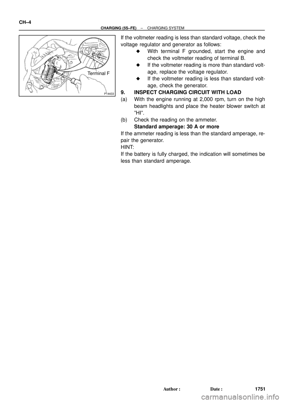
P14433
Terminal F CH±4
± CHARGING (5S±FE)CHARGING SYSTEM
1751 Author�: Date�:
If the voltmeter reading is less than standard voltage, check the
voltage regulator and generator as follows:
�With terminal F grounded, start the engine and
check the voltmeter reading of terminal B.
�If the voltmeter reading is more than standard volt-
age, replace the voltage regulator.
�If the voltmeter reading is less than standard volt-
age, check the generator.
9. INSPECT CHARGING CIRCUIT WITH LOAD
(a) With the engine running at 2,000 rpm, turn on the high
beam headlights and place the heater blower switch at
ºHIº.
(b) Check the reading on the ammeter.
Standard amperage: 30 A or more
If the ammeter reading is less than the standard amperage, re-
pair the generator.
HINT:
If the battery is fully charged, the indication will sometimes be
less than standard amperage.
Page 2299 of 4770
CH02V±03
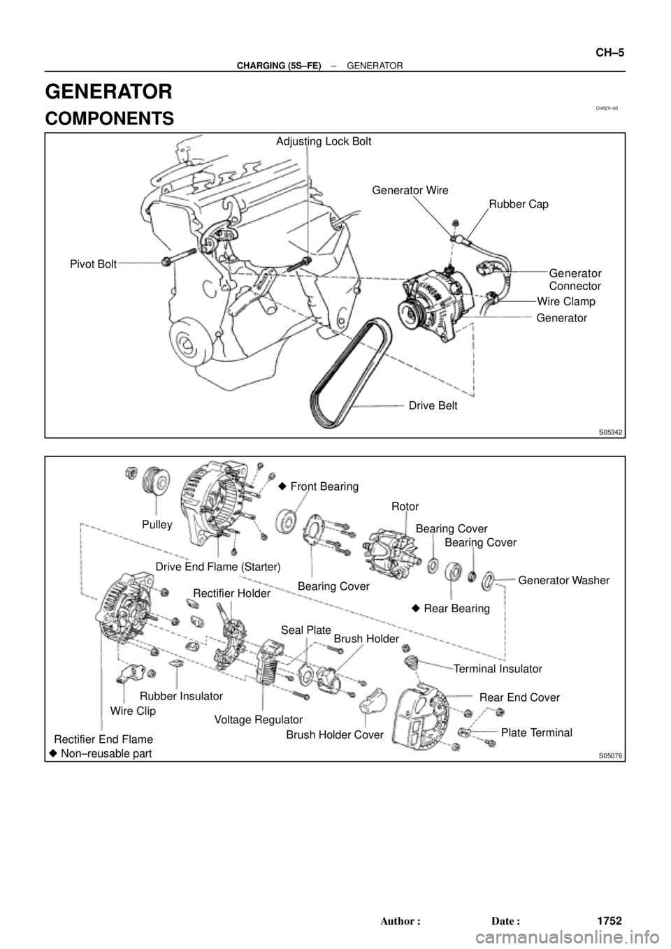
S05342
Pivot BoltAdjusting Lock Bolt
Generator Wire
Generator
Connector
Generator
Drive Belt
Rubber Cap
Wire Clamp
S05076
Pulley
Drive End Flame (Starter)� Front Bearing
Bearing CoverRotor
Generator Washer
Rectifier End FlameWire ClipRubber InsulatorRectifier Holder
Voltage RegulatorSeal Plate
Brush Holder
Brush Holder CoverTerminal Insulator
Rear End Cover
Plate Terminal
� Non±reusable partBearing Cover
� Rear BearingBearing Cover
± CHARGING (5S±FE)GENERATOR
CH±5
1752 Author�: Date�:
GENERATOR
COMPONENTS
Page 2300 of 4770
CH02W±03
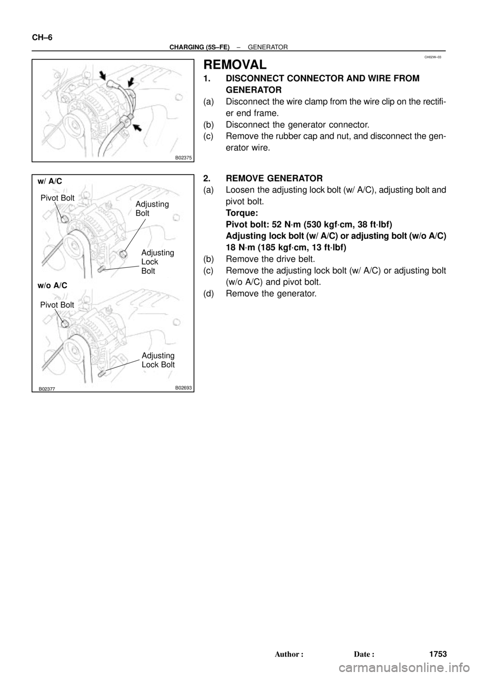
B02375
B02376B02377B02693
w/o A/C
w/ A/C
Pivot BoltAdjusting
Bolt
Adjusting
Lock
Bolt
Pivot Bolt
Adjusting
Lock Bolt
CH±6
± CHARGING (5S±FE)GENERATOR
1753 Author�: Date�:
REMOVAL
1. DISCONNECT CONNECTOR AND WIRE FROM
GENERATOR
(a) Disconnect the wire clamp from the wire clip on the rectifi-
er end frame.
(b) Disconnect the generator connector.
(c) Remove the rubber cap and nut, and disconnect the gen-
erator wire.
2. REMOVE GENERATOR
(a) Loosen the adjusting lock bolt (w/ A/C), adjusting bolt and
pivot bolt.
Torque:
Pivot bolt: 52 N´m (530 kgf´cm, 38 ft´lbf)
Adjusting lock bolt (w/ A/C) or adjusting bolt (w/o A/C)
18 N´m (185 kgf´cm, 13 ft´lbf)
(b) Remove the drive belt.
(c) Remove the adjusting lock bolt (w/ A/C) or adjusting bolt
(w/o A/C) and pivot bolt.
(d) Remove the generator.
Page 2301 of 4770
CH02X±01
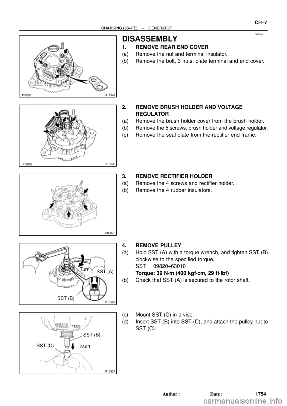
Z18635
Z18636
B02378
P13597SST (B)
SST (A) Turn
P10834
SST (B)
SST (C)
Insert
± CHARGING (5S±FE)GENERATOR
CH±7
1754 Author�: Date�:
DISASSEMBLY
1. REMOVE REAR END COVER
(a) Remove the nut and terminal insulator.
(b) Remove the bolt, 3 nuts, plate terminal and end cover.
2. REMOVE BRUSH HOLDER AND VOLTAGE
REGULATOR
(a) Remove the brush holder cover from the brush holder.
(b) Remove the 5 screws, brush holder and voltage regulator.
(c) Remove the seal plate from the rectifier end frame.
3. REMOVE RECTIFIER HOLDER
(a) Remove the 4 screws and rectifier holder.
(b) Remove the 4 rubber insulators.
4. REMOVE PULLEY
(a) Hold SST (A) with a torque wrench, and tighten SST (B)
clockwise to the specified torque.
SST 09820±63010
Torque: 39 N´m (400 kgf´cm, 29 ft´lbf)
(b) Check that SST (A) is secured to the rotor shaft.
(c) Mount SST (C) in a vise.
(d) Insert SST (B) into SST (C), and attach the pulley nut to
SST (C).
Page 2302 of 4770
P10827
SST (C)
SST (A)
Turn
P13598SST (B)
SST (A) Turn
S05070
P13490
SST CH±8
± CHARGING (5S±FE)GENERATOR
1755 Author�: Date�:
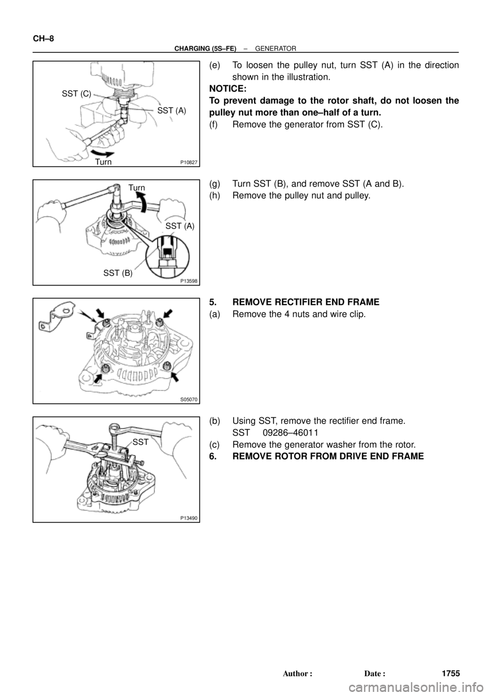
(e) To loosen the pulley nut, turn SST (A) in the direction
shown in the illustration.
NOTICE:
To prevent damage to the rotor shaft, do not loosen the
pulley nut more than one±half of a turn.
(f) Remove the generator from SST (C).
(g) Turn SST (B), and remove SST (A and B).
(h) Remove the pulley nut and pulley.
5. REMOVE RECTIFIER END FRAME
(a) Remove the 4 nuts and wire clip.
(b) Using SST, remove the rectifier end frame.
SST 09286±46011
(c) Remove the generator washer from the rotor.
6. REMOVE ROTOR FROM DRIVE END FRAME
Page 2303 of 4770
GENERATOR
CH±9
1756 Author�: Date�:
INSPECTION
1")
CH02Y±01
CH0784
Ohmmeter
Continuity
CH0783
Ohmmeter
No Continuity
CH1023
P13482
Ohmmeter
Continuity
P13565
Ohmmeter
No Continuity
± CHARGING (5S±FE)GENERATOR
CH±9
1756 Author�: Date�:
INSPECTION
1. INSPECT ROTOR
(a) Check the rotor for open circuit.
Using an ohmmeter, check that there is continuity be-
tween the slip rings.
Standard resistance: 2.7 ± 3.1 W at 20°C (68°F)
If there is no continuity, replace the rotor.
(b) Check the rotor for ground.
Using an ohmmeter, check that there is no continuity be-
tween the slip ring and rotor.
If there is continuity, replace the rotor.
(c) Check that the slip rings are not rough or scored.
If rough or scored, replace the rotor.
(d) Using vernier calipers, measure the slip ring diameter.
Standard diameter: 14.2 ± 14.4 mm (0.559 ± 0.567 in.)
Minimum diameter: 12.8 mm (0.504 in.)
If the diameter is less than minimum, replace the rotor.
2. INSPECT STATOR (DRIVE END FRAME)
(a) Check the stator for open circuit.
Using an ohmmeter, check that there is continuity be-
tween the coil leads.
If there is no continuity, replace the drive end frame assembly.
(b) Check the stator for ground.
Using an ohmmeter, check that there is no continuity be-
tween the coil lead and drive end frame.
If there is continuity, replace the drive end frame assembly.