Page 1507 of 4770

FuseSystemPage
15ASTOP
ABS (TMC Made)
ABS (TMMK Made)
ABS and Traction Control
Cruise Control
Electronically Controlled Transmission and A/T Indicator (1MZ±FE)
El")
K POWER SOURCE (Current Flow Chart)
FuseSystemPage
15ASTOP
ABS (TMC Made)
ABS (TMMK Made)
ABS and Traction Control
Cruise Control
Electronically Controlled Transmission and A/T Indicator (1MZ±FE)
Electronically Controlled Transmission and A/T Indicator (5S±FE)
Engine Control (1MZ±FE)
Engine Control (5S±FE)
Shift Lock
Stop Light234
240
226
218
202
210
66
82
252
11 8
25AWIPERWiper and Washer140
25ADOOR
Door Lock Control (TMC Made)
Door Lock Control (TMMK Made)
Moon Roof
Power Window
Theft Deterrent (TMC Made)
Theft Deterrent (TMMK Made)
Wireless Door Lock Control (TMC Made)
Wireless Door Lock Control (TMMK Made)150
156
194
144
182
188
162
172
30APOWER
Door Lock Control (TMC Made)
Door Lock Control (TMMK Made)
Moon Roof
Power Seat
Power Window150
156
194
198
144
40AAM1Charging
Radiator Fan and Condenser Fan62
288
40ADEFRear Window Defogger and Mirror Heater268
Engine Room J/B No.2 (See Page 22)
FuseSystemPage
5AALT±SCharging62
7.5ADOME
Cigarette Lighter and Clock
Combination Meter
Headlight (w/ Daytime Running Light)
Interior Light
Key Reminder and Seat Belt Warning
Light Auto Turn Off
Moon Roof
Theft Deterrent (TMC Made)
Theft Deterrent (TMMK Made)
Wireless Door Lock Control (TMC Made)
Wireless Door Lock Control (TMMK Made)258
280
100
122
260
11 0
194
182
188
162
172
*These are the page numbers of the first page on which the related system is shown.
Page 1508 of 4770

Combination Meter
SRS292
280
245
10AHAZARDTurn Signal and Hazard Warning Light11 4
10AHORN
Horn
Theft Deterrent (TMC Made)
Theft Deterrent (")
K
FuseSystemPage
10AECU±B
Air Conditioning (Automatic A/C)
Combination Meter
SRS292
280
245
10AHAZARDTurn Signal and Hazard Warning Light11 4
10AHORN
Horn
Theft Deterrent (TMC Made)
Theft Deterrent (TMMK Made)
Wireless Door Lock Control (TMC Made)
Wireless Door Lock Control (TMMK Made)256
182
188
162
172
15AEFI
Electronically Controlled Transmission and A/T Indicator (1MZ±FE)
Electronically Controlled Transmission and A/T Indicator (5S±FE)
Engine Control (1MZ±FE)
Engine Control (5S±FE)
Engine Immobiliser System202
210
66
82
94
15AHEAD (LH)Headlight (w/o Daytime Running Light)96
15AHEAD (RH)Headlight (w/o Daytime Running Light)96
15AHEAD LH (UPR)Headlight (w/ Daytime Running Light)100
15AHEAD RH (UPR)Headlight (w/ Daytime Running Light)100
20ARADIO NO.1
Auto Antenna
Radio and Player (Built±In Type Amplifier)
Radio and Player (Separate Type Amplifier)272
278
274
30AAM2
Charging
Engine Control (1MZ±FE)
Engine Control (5S±FE)
Starting and Ignition (1MZ±FE)
Starting and Ignition (5S±FE)62
66
82
54
58
30ACDSRadiator Fan and Condenser Fan288
30ARDIRadiator Fan and Condenser Fan288
40AMAIN
Headlight (w/ Daytime Running Light)
Headlight (w/o Daytime Running Light)
Light Auto Turn Off
Starting and Ignition (1MZ±FE)
Starting and Ignition (5S±FE)
Theft Deterrent (TMC Made)
Theft Deterrent (TMMK Made)
Wireless Door Lock Control (TMC Made)
Wireless Door Lock Control (TMMK Made)100
96
11 0
54
58
182
188
162
172
Engine Room R/B No.1 (See Page 24)
FuseSystemPage
10AA/CAir Conditioning (Manual A/C)300
25AA/F HTREngine Control (1MZ±FE)66
*These are the page numbers of the first page on which the related system is shown.
Page 1523 of 4770

AC2810
AC0LG±02
AC2811
N11084
Wrong Okey
HI LO HILO
± AIR CONDITIONINGAIR CONDITIONING SYSTEM
AC±1
2483 Author�: Date�:
AIR CONDITIONING SYSTEM
PRECAUTION
1. DO NOT HANDLE REFRIGERANT IN AN ENCLOSED
AREA OR WEAR EYE PROTECTION
2. ALWAYS WEAR EYE PROTECTION
3. BE CAREFUL NOT TO GET LIQUID REFRIGERANT IN
YOUR EYES OR ON YOUR SKIN
If liquid refrigerant gets in your eyes or on your skin.
(a) Wash the area with lots of cool water.
CAUTION:
Do not rub your eyes or skin.
(b) Apply clean petroleum jelly to the skin.
(c) Go immediately to a physician or hospital for professional
treatment.
4. NEVER HEAT CONTAINER OR EXPOSE IT TO NAKED
FLAME
5. BE CAREFUL NOT TO DROP CONTAINER AND NOT
TO APPLY PHYSICAL SHOCKS TO IT
6. DO NOT OPERATE COMPRESSOR WITHOUT
ENOUGH REFRIGERANT IN REFRIGERATION SYS-
TEM
If there is not enough refrigerant in the refrigerant system oil lu-
brication will be insufficient and compressor burnout may occur,
so that care to avoid this, necessary care should be taken.
7. DO NOT OPEN PRESSURE MANIFOLD VALVE WHILE
COMPRESSOR IS OPERATE
If the high pressure valve is opened, refrigerant flows in the re-
verse direction and could cause the charging cylinder to rup-
ture, so open and close the only low pressure valve.
8. BE CAREFUL NOT TO OVERCHARGE SYSTEM WITH
REFRIGERANT
If refrigerant is overcharged, it causes problems such as insuffi-
cient cooling, poor fuel economy, engine overheating etc.
Page 1532 of 4770

AC0LJ±03
N13795
Quick Disconnect
Adapter
Charging
Service ValveHose
N13794
Vacuum Pump
Vacuum Pump Adapter
N13791
Low Pressure
Service Valve
Vacuum Pump Adapter High Pressure
Service ValveManifold
Gauge
Set
AC±10
± AIR CONDITIONINGAIR CONDITIONING SYSTEM
2492 Author�: Date�:
EVACUATING
1. CONNECT QUICK DISCONNECT ADAPTER TO
CHARGING HOSES
2. REMOVE CAPS FROM SERVICE VALVES ON RE-
FRIGERANT LINES
3. SET ON MANIFOLD GAUGE SET
(a) Close both hand valves of manifold gauge set.
(b) Connect the quick disconnect adapters to the service
valves.
4. EVACUATE AIR FROM REFRIGERATION SYSTEM
(a) Connect the vacuum pump adapter to the vacuum pump.
(b) Connect the center hose of the manifold gauge set to the
vacuum pump adapter.
(c) Open both the high and low hand valves and run the vacu-
um pump.
(d) After 10 minutes or more, check that the low pressure
gauge indicates 750 mmHg (30 in. Hg) or more.
HINT:
If the reading 750 mmHg (30 in. Hg) or more, close both hand
valves of manifold gauge set and stop the vacuum pump.
Check the system for leaks and repair necessary.
(e) Close both the high and low hand valves and stop the vac-
uum pump.
(f) Leave the system in this condition for 5 minutes or more
and check that there is no gauge indicator.
Page 1533 of 4770

AC21S±01
N13793
Charging Cylinder High Pressure
Service Valve Low Pressure
Service ValvePush
Air
N13792
Gas Leak
Detector
± AIR CONDITIONINGAIR CONDITIONING SYSTEM
AC±11
2493 Author�: Date�:
CHARGING
1. INSTALL CHARGING CYLINDER
HINT:
When handling the charging cylinder, always follow the direc-
tions given in the instruction manual.
(a) Charge the proper amount of refrigerant into the charging
cylinder.
(b) Connect the center hose to the charging cylinder.
CAUTION:
Do not open both high and low hand valves of manifold
gauge set.
(c) Open the valve of charging cylinder.
(d) Press the valve core on the side of manifold gauge and
expel the air inside of the center hose.
2. INSPECT REFRIGERATION SYSTEM FOR LEAKS
(a) Open the high pressure hand valve and charge refriger-
ant.
(b) When the low pressure gauge indicates 98 kPa
(1 kgf/cm
2, 14 psi) close the high pressure hand valve.
(c) Using a gas leak detector, check the system for leakage.
(d) If leak is found, repair the faulty component or connection.
CAUTION:
Use the refrigerant recovery/ recycling machine to recover
the refrigerant whenever replacing parts.
Page 1534 of 4770

N13790
Low Pressure
Service Valve
High Pressure
Service Valve
I07055
Properly
Charged
Insufficiently
Charged AC±12
± AIR CONDITIONINGAIR CONDITIONING SYSTEM
2494 Author�: Date�:
3. CHARGE REFRIGERANT INTO REFRIGERANT SYS-
TEM
If there is no leak after refrigerant leak check, charge the proper
amount of refrigerant into refrigeration system.
CAUTION:
�Never run the engine when charging the system
through the high pressure side.
�Do not open the low pressure hand valve when the
system is being charged with liquid refrigerant.
(a) Open the high pressure hand valve fully.
(b) Charge specified amount of refrigerant, then close the
high pressure hand valve.
HINT:
A fully charged system is indicated by the sight glass being free
of any bubbles.
(c) Charge partially refrigeration system with refrigerant.
(1) Set vehicle in these conditions:
�Running engine at 1,500 rpm
�Blower speed control set at ºHIº
�Temperature control set at ºMAX. COOLº
�Air inlet control set at ºRECIRCº
�Fully open doors (Sliding roof: closed)
(2) Open the low pressure hand valve.
CAUTION:
Do not open the high pressure hand valve.
(d) Charge refrigerant until bubbles disappear and check the
pressure on the gauge through the sight glass.
Page 1541 of 4770
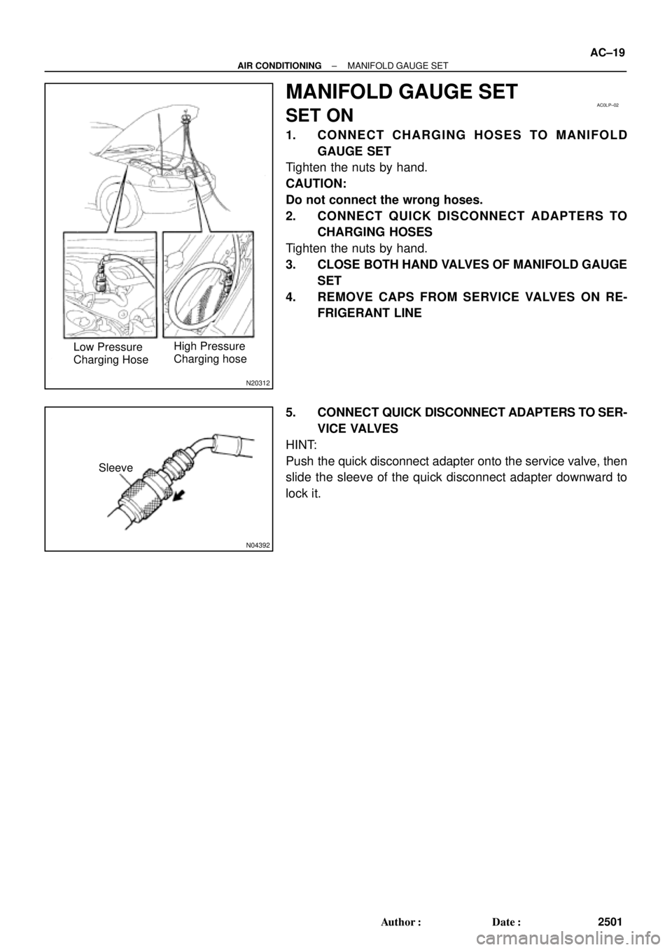
N20312
High Pressure
Charging hose Low Pressure
Charging Hose
AC0LP±02
N04392
Sleeve
± AIR CONDITIONINGMANIFOLD GAUGE SET
AC±19
2501 Author�: Date�:
MANIFOLD GAUGE SET
SET ON
1. CONNECT CHARGING HOSES TO MANIFOLD
GAUGE SET
Tighten the nuts by hand.
CAUTION:
Do not connect the wrong hoses.
2. CONNECT QUICK DISCONNECT ADAPTERS TO
CHARGING HOSES
Tighten the nuts by hand.
3. CLOSE BOTH HAND VALVES OF MANIFOLD GAUGE
SET
4. REMOVE CAPS FROM SERVICE VALVES ON RE-
FRIGERANT LINE
5. CONNECT QUICK DISCONNECT ADAPTERS TO SER-
VICE VALVES
HINT:
Push the quick disconnect adapter onto the service valve, then
slide the sleeve of the quick disconnect adapter downward to
lock it.
Page 2295 of 4770
CHARGING SYSTEM
CH±1
1748 Author�: Date�:
CHARGING SYSTEM
ON±VEHICLE INSPECTION
CAUTI")
CH02U±01
Z11577
Except Maintenance±Free Battery
Z11556
Maintenance±Free Battery
Voltmeter
± CHARGING (5S±FE)CHARGING SYSTEM
CH±1
1748 Author�: Date�:
CHARGING SYSTEM
ON±VEHICLE INSPECTION
CAUTION:
�Check that the battery cables are connected to the
correct terminals.
�Disconnect the battery cables when the battery is giv-
en a quick charge.
�Do not perform tests with a high voltage insulation re-
sistance tester.
�Never disconnect the battery while the engine is run-
ning.
1. CHECK BATTERY ELECTROLYTE LEVEL
Check the electrolyte quantity of each cell.
Maintenance±Free Battery:
If under the lower level, replace the battery (or add distilled wa-
ter if possible). Check the charging system.
Except Maintenance±Free Battery:
If under the lower level, add distilled water.
2. Except Maintenance±Free Battery:
CHECK BATTERY SPECIFIC GRAVITY
Check the specific gravity of each cell.
Standard specific gravity:
1.25 ± 1.29 at 20°C (68°F)
If the specific gravity is less than specification, charge the bat-
tery.
3. Maintenance±Free Battery:
CHECK BATTERY VOLTAGE
(a) After having driven the vehicle and in the case that 20
minutes have not passed after having stopped the en-
gine, turn the ignition switch ON and turn on the electrical
system (headlight, blower motor, rear defogger etc.) for
60 seconds to remove the surface charge.
(b) Turn the ignition switch OFF and turn off the electrical sys-
tems.
(c) Measure the battery voltage between the negative (±)
and positive (+) terminals of the battery.
Standard voltage: 12.5 ± 12.9 V at 20°C (68°F)
If the voltage is less than specification, charge the battery.