Page 3766 of 4770
MANUAL TRANSAXLE UNIT
MX±7
1857 Author�: Date�:
23. REMOVE FRONT SUSPENSION MEMBER WITH LOW-
ER SUSPENSION ARM
(a) Remove the LH and RH f")
Q10008
C
C
A
CBA
ABC A
Q10011
Q10009
± MANUAL TRANSAXLE (S51)MANUAL TRANSAXLE UNIT
MX±7
1857 Author�: Date�:
23. REMOVE FRONT SUSPENSION MEMBER WITH LOW-
ER SUSPENSION ARM
(a) Remove the LH and RH fender liner set screws.
(b) Remove the 6 bolts, 4 nuts, front LH and RH suspension
member braces, rear LH and RH suspension member
braces and front suspension member with the lower sus-
pension arm.
Torque:
Bolt A: 181 N´m (1,850 kgf´cm, 134 ft´lbf)
Bolt B: 32 N´m (330 kgf´cm, 24 ft´lbf)
Nut C: 36 N´m (370 kgf´cm, 27 ft´lbf)
24. JACK UP TRANSAXLE SLIGHTLY
Using a transmission jack, support the transaxle.
25. REMOVE LH STIFFENER PLATE
Remove the 3 bolts and LH stiffener plate.
Torque: 37 N´m (380 kgf´cm, 27 ft´lbf)
26. REMOVE REAR END PLATE WITH OIL PAN INSULA-
TOR AND RH STIFFENER PLATE
(a) Remove the 2 bolts and rear end plate with the oil pan in-
sulator.
Torque: 9.3 N´m (95 kgf´cm, 82 in.´lbf)
(b) Remove the 2 bolts and manifold stay.
Torque: 39 N´m (400 kgf´cm, 29 ft´lbf)
(c) Remove the 4 bolts and RH stiffener plate.
Torque: 39 N´m (400 kgf´cm, 29 ft´lbf)
27. REMOVE TRANSAXLE
Lower the engine left side and remove the transaxle from the
engine.
HINT:
At the time of installation, please refer to the following items.
�Align the input shaft with the clutch disc and install the
transaxle to the engine.
�Temporarily tighten the transaxle mounting bolts.
Page 3784 of 4770
INPUT SHAFT
MX±25
1875 Author�: Date�:
REASSEMBLY
HINT:
Coat all of the sliding and rotating surfaces with gear oil before
r")
MX04M±01
SM0282
Engine
Side
SM0193
Z00419
Z00604
± MANUAL TRANSAXLE (S51)INPUT SHAFT
MX±25
1875 Author�: Date�:
REASSEMBLY
HINT:
Coat all of the sliding and rotating surfaces with gear oil before
reassembly.
1. INSTALL NO.2 CLUTCH HUB INTO HUB SLEEVE
(a) Install the clutch hub and shifting keys to the hub sleeve.
(b) Install the shifting key springs under the shifting keys.
NOTICE:
Position the key springs so that their end gaps are not
aligned.
2. INSTALL 3RD GEAR, NEEDLE ROLLER BEARING,
SYNCHRONIZER RING AND NO.2 HUB SLEEVE AS-
SEMBLY TO INPUT SHAFT
(a) Apply gear oil to the needle roller bearings.
(b) Place the synchronizer ring (for the 3rd gear) on the gear
and align the ring slots with the shifting keys.
NOTICE:
Do not install the synchronizer ring for 4th gear.
(c) Using a press, install the 3rd gear and No.2 hub sleeve.
3. INSTALL SNAP RING
(a) Select a snap ring that allows the minimum axial play.
MarkThickness mm (in.)
11.95±2.00 (0.0768±0.0787)
22.00±2.05 (0.0787±0.0807)
32.05±2.10 (0.0807±0.0827)
42.10±2.15 (0.0827±0.0846)
52.15±2.20 (0.0846±0.0866)
62.20±2.25 (0.0866±0.0886)
Page 3807 of 4770
MANUAL TRANSAXLE UNIT
MX±5
1806 Author�: Date�:
10. REMOVE 5 TRANSAXLE UPPER SIDE MOUNTING
BOLTS
Torque:
17 m")
Q09986
Q09987
Filler Plug
Oil Level
0 ± 5 mm
Drain Plug
Q09988
± MANUAL TRANSAXLE (E153)MANUAL TRANSAXLE UNIT
MX±5
1806 Author�: Date�:
10. REMOVE 5 TRANSAXLE UPPER SIDE MOUNTING
BOLTS
Torque:
17 mm head: 64 N´m (650 kgf´cm, 47 ft´lbf)
11. REMOVE FRONT WHEEL
Torque: 103 N´m (1,050 kgf´cm, 76 ft´lbf)
12. RAISE VEHICLE
NOTICE:
Make sure that the vehicle is securely supported.
13. REMOVE ENGINE REAR SIDE SHUTTER PLATE AND
LH AND RH FENDER APRON SEALS
14. DRAIN TRANSAXLE OIL
Oil grade: API GL±4 or GL±5
Viscosity: SAE 75W±90
Capacity: 4.2 liters (4.4 US qts, 3.7 Imp. qts)
Torque: 49 N´m (500 kgf´cm, 36 ft´lbf)
15. REMOVE LH AND RH DRIVE SHAFTS
(See page SA±25)
16. REMOVE FRONT EXHAUST PIPE
(a) Remove the 2 bolts and exhaust pipe support stay.
Torque: 33 N´m (330 kgf´cm, 24 ft´lbf)
(b) Remove the 4 nuts and 2 gaskets from the exhaust man-
ifold.
Torque: 62 N´m (630 kgf´cm, 46 ft´lbf)
(c) Remove the 2 bolts, nuts and gasket.
Torque: 56 N´m (570 kgf´cm, 41 ft´lbf)
(d) Remove the 2 set bolts of the No.1 exhaust pipe support
bracket.
Torque: 33 N´m (330 kgf´cm, 24 ft´lbf)
(e) Remove the front exhaust pipe.
Page 3853 of 4770
PP0JQ±04
PP±2
± PREPARATIONENGINE MECHANICAL (5S±FE)
54 Author�: Date�:
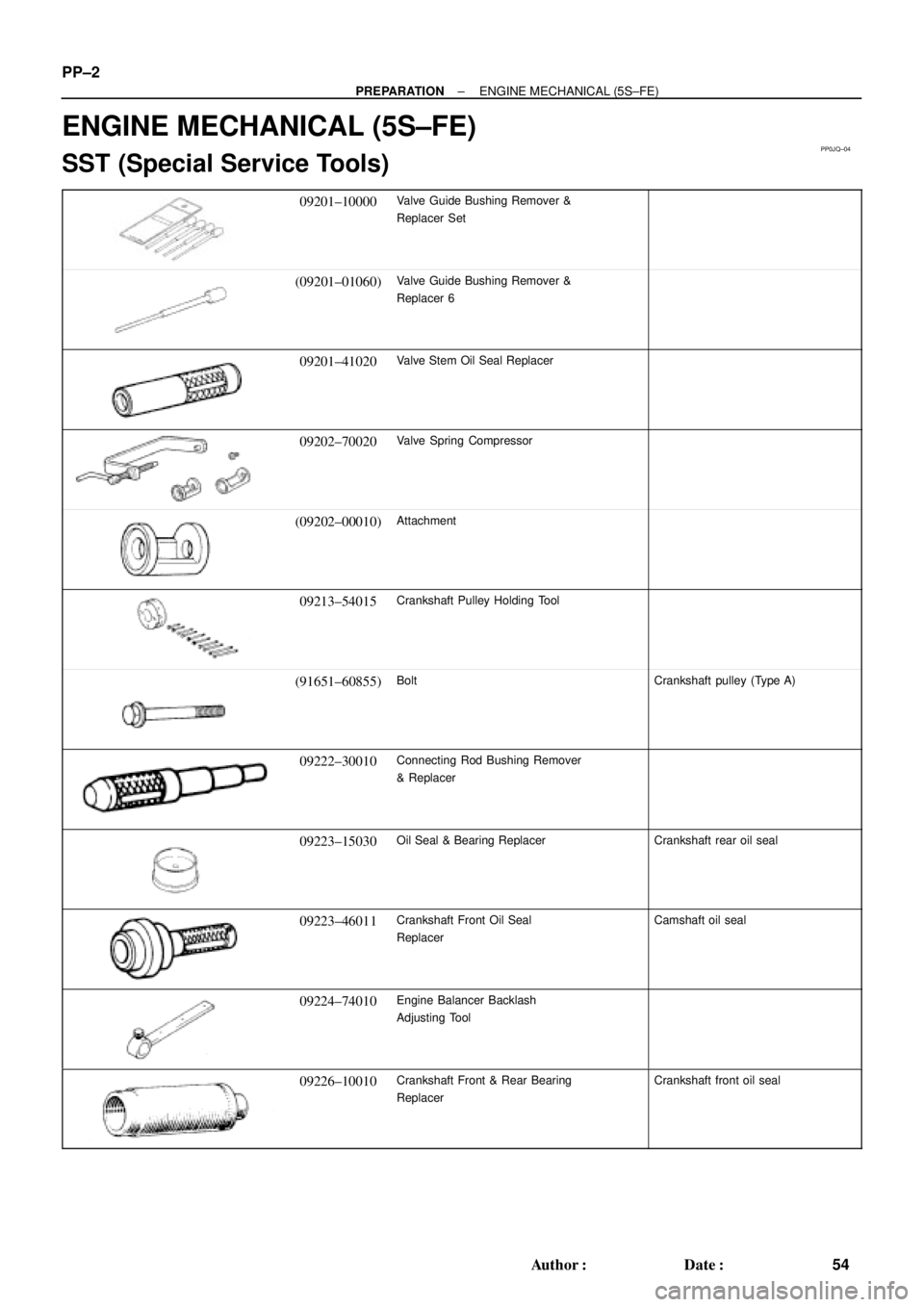
ENGINE MECHANICAL (5S±FE)
SST (Special Service Tools)
09201±10000Valve Guide Bushing Remover &
Replacer Set
(09201±01060)Valve Guide Bushing Remover &
Replacer 6
09201±41020Valve Stem Oil Seal Replacer
09202±70020Valve Spring Compressor
(09202±00010)Attachment
09213±54015Crankshaft Pulley Holding Tool
(91651±60855)BoltCrankshaft pulley (Type A)
09222±30010Connecting Rod Bushing Remover
& Replacer
09223±15030Oil Seal & Bearing ReplacerCrankshaft rear oil seal
09223±46011Crankshaft Front Oil Seal
ReplacerCamshaft oil seal
09224±74010Engine Balancer Backlash
Adjusting Tool
09226±10010Crankshaft Front & Rear Bearing
ReplacerCrankshaft front oil seal
Page 3855 of 4770
PP±4
± PREPARATIONENGINE MECHANICAL (5S±FE)
56 Author�: Date�:
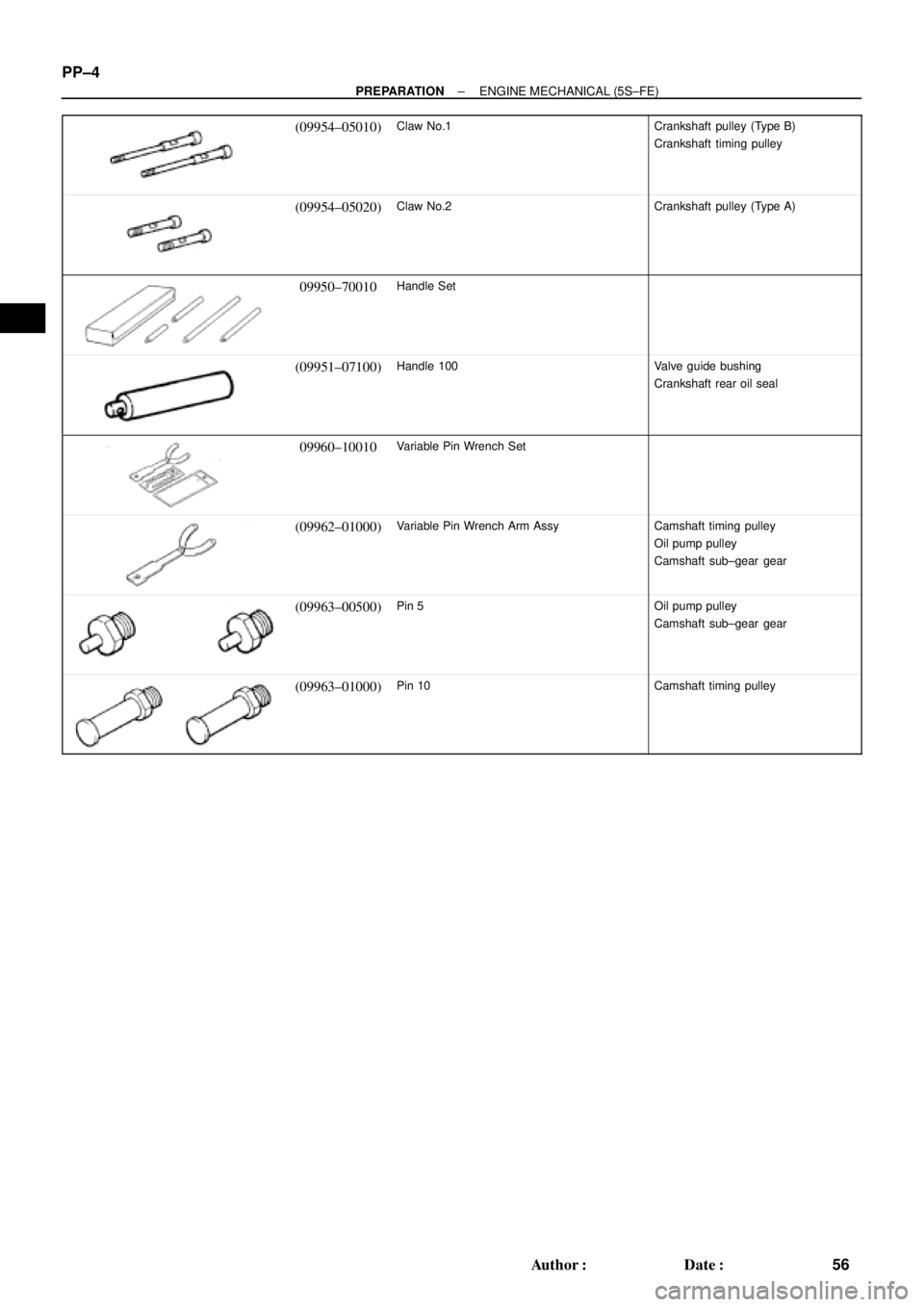
(09954±05010)Claw No.1Crankshaft pulley (Type B)
Crankshaft timing pulley
(09954±05020)Claw No.2Crankshaft pulley (Type A)
09950±70010Handle Set
(09951±07100)Handle 100Valve guide bushing
Crankshaft rear oil seal
09960±10010Variable Pin Wrench Set
(09962±01000)Variable Pin Wrench Arm AssyCamshaft timing pulley
Oil pump pulley
Camshaft sub±gear gear
(09963±00500)Pin 5Oil pump pulley
Camshaft sub±gear gear
(09963±01000)Pin 10Camshaft timing pulley
Page 3858 of 4770
PP1WA±02
± PREPARATIONENGINE MECHANICAL (5S±FE)
PP±7
59 Author�: Date�:
SSM (Special Service Materials)
08826±00080Seal Packing Black or equivalent
(FIPG)Camshaft bearing cap
Cylinder head cover
Semi±circular plug
08833±00070Adhesive 1324,
THREE BOND 1324 or equivalentFlywheel or drive plate bolt
Torque converter clutch bolt
08833±00080Adhesive 1344
THREE BOND 1344
LOCTITE 242 or equivalentOil pressure switch
Page 3859 of 4770
PP0BR±03
PP±8
± PREPARATIONENGINE MECHANICAL (1MZ±FE)
60 Author�: Date�:
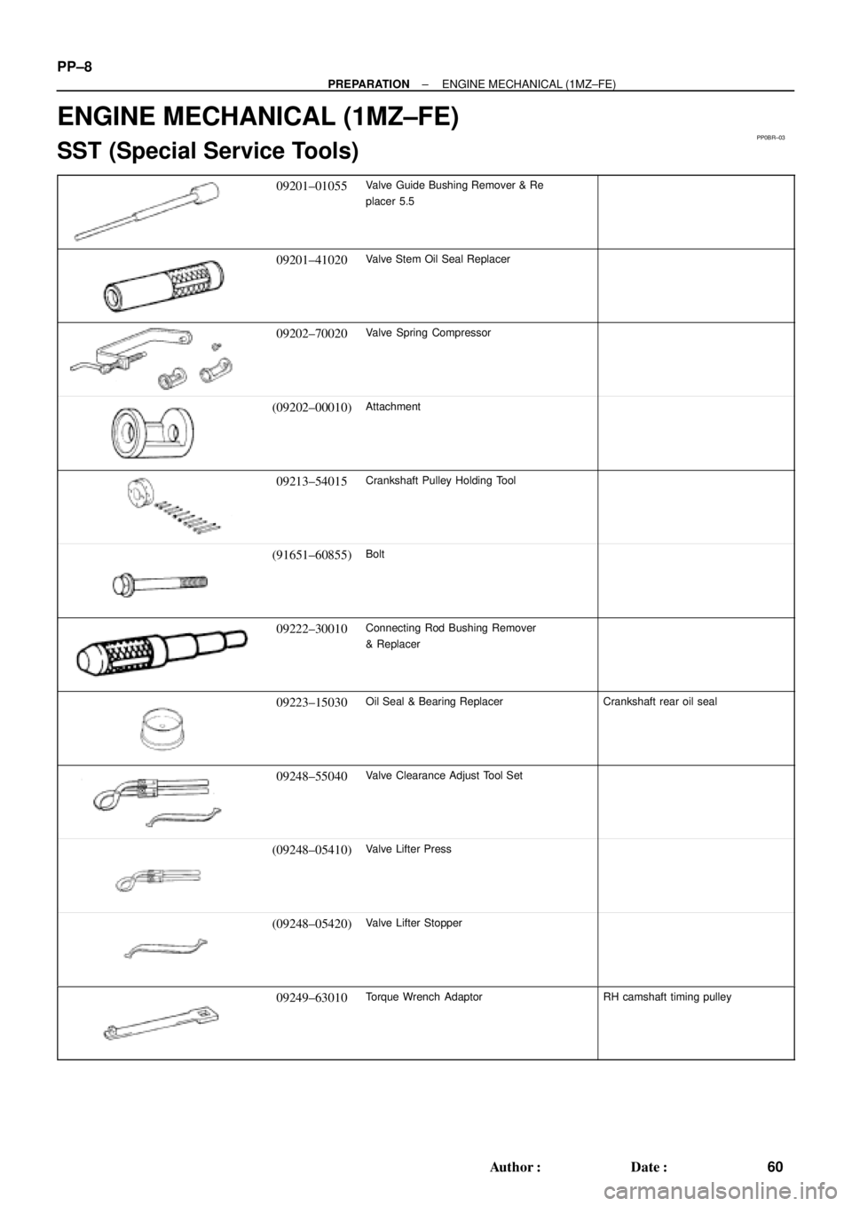
ENGINE MECHANICAL (1MZ±FE)
SST (Special Service Tools)
09201±01055Valve Guide Bushing Remover & Re
placer 5.5
09201±41020Valve Stem Oil Seal Replacer
09202±70020Valve Spring Compressor
(09202±00010)Attachment
09213±54015Crankshaft Pulley Holding Tool
(91651±60855)Bolt
09222±30010Connecting Rod Bushing Remover
& Replacer
09223±15030Oil Seal & Bearing ReplacerCrankshaft rear oil seal
09248±55040Valve Clearance Adjust Tool Set
(09248±05410)Valve Lifter Press
(09248±05420)Valve Lifter Stopper
09249±63010Torque Wrench AdaptorRH camshaft timing pulley
Page 3860 of 4770
± PREPARATIONENGINE MECHANICAL (1MZ±FE)
PP±9
61 Author�: Date�:
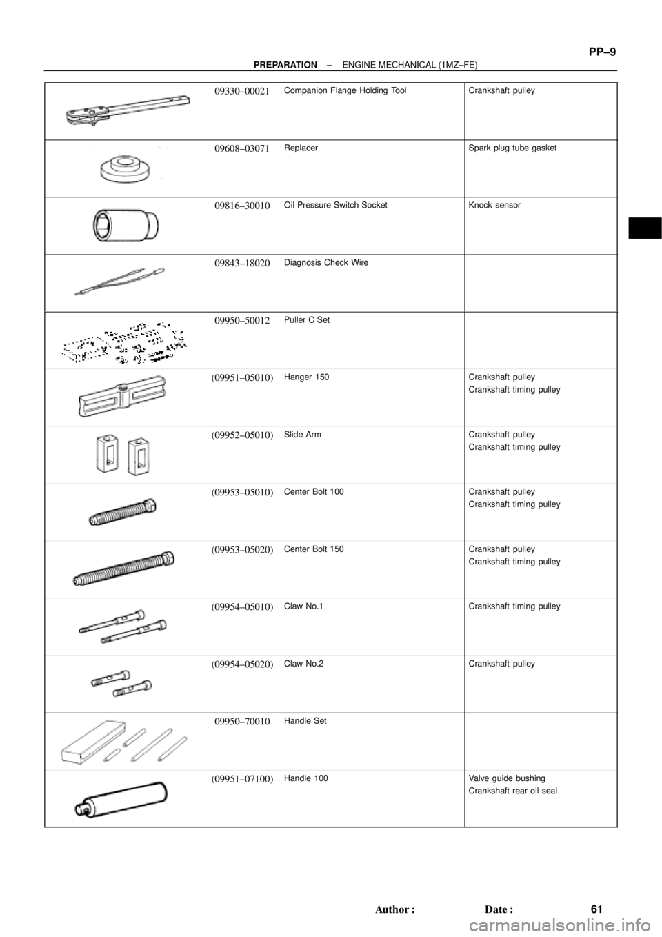
09330±00021Companion Flange Holding ToolCrankshaft pulley
09608±03071ReplacerSpark plug tube gasket
09816±30010Oil Pressure Switch SocketKnock sensor
09843±18020Diagnosis Check Wire
09950±50012Puller C Set
(09951±05010)Hanger 150Crankshaft pulley
Crankshaft timing pulley
(09952±05010)Slide ArmCrankshaft pulley
Crankshaft timing pulley
(09953±05010)Center Bolt 100Crankshaft pulley
Crankshaft timing pulley
(09953±05020)Center Bolt 150Crankshaft pulley
Crankshaft timing pulley
(09954±05010)Claw No.1Crankshaft timing pulley
(09954±05020)Claw No.2Crankshaft pulley
09950±70010Handle Set
(09951±07100)Handle 100Valve guide bushing
Crankshaft rear oil seal