Page 2119 of 4770

CIRCUIT
Disconnect the connector from the relay a")
I08219
Wire harness side:
± BODY ELECTRICALHEADLIGHT AND TAILLIGHT SYSTEM
BE±25
2245 Author�: Date�:
6. INSPECT DAYTIME RUNNING LIGHT RELAY (MAIN)
CIRCUIT
Disconnect the connector from the relay and inspect the con-
nector on the wire harness side.
Tester connectionConditionSpecified condition
2 ± GroundLight control switch position OFF or TAILNo continuity
2 ± GroundLight control switch position HEADContinuity
3 ± GroundHeadlight dimmer switch position
Low beamNo continuity
3 ± GroundHeadlight dimmer switch position
High beam of FlashContinuity
4 ± GroundBrake fluid level warning position OFFNo continuity
4 ± GroundBrake fluid level warning position ONContinuity
12 ± GroundConstantContinuity
14 ± GroundParking brake switch position OFF
(Parking brake lever released)No continuity
14 ± GroundParking brake switch position ON
(Parking brake lever pulled up)Continuity
17 ± GroundLight control switch position OFF or HEADNo voltage
17 ± GroundLight control switch position TAILContinuity
20 ± GroundConstantContinuity
21 ± GroundConstantContinuity
13 ± GroundEngine StopNo voltage
13 ± GroundEngine RunningBattery positive voltage
16 ± GroundConstantBattery positive voltage
18 ± GroundGround terminal 19Battery positive voltage
19 ± GroundConstantBattery positive voltage
22 ± GroundConstantBattery positive voltage
23 ± GroundIgnition switch position LOCK or ACCNo voltage
23 ± GroundIgnition switch position ON or STARTBattery positive voltage
If circuit is as specified, try replacing the relay with a new one.
If circuit is not as specified, inspect the circuits connected to oth-
er parts.
Page 2120 of 4770

Z08559
1
2
341 2
43
N20139
1 2
I08422
I08423
BE±26
± BODY ELECTRICALHEADLIGHT AND TAILLIGHT SYSTEM
2246 Author�: Date�:
7. INSPECT DAYTIME RUNNING LIGHT NO.4 RELAY
CONTINUITY
ConditionTester connectionSpecified condition
Constant3 ± 4Continuity
Apply B+ between
terminals 3 and 4.1 ± 2Continuity
If continuity is not as specified, replace the relay.
8. INSPECT DAYTIME RUNNING LIGHT RESISTER CON-
TINUITY
ConditionTester connectionSpecified condition
Constant1 ± 2Approx. 250mW
If continuity is not as specified, replace the resistor.
9. INSPECT LIGHT AUTO TURN OFF SYSTEM
(See Integration relay circuit on page BE±14)
10. INSPECT AUTOMATIC LIGHT CONTROL
(a) Turn the ignition switch ON.
(b) Turn the light control switch to OFF.
(c) Parking brake lever released.
(d) Gradually cover the top of the sensor.
(e) Verify that the lights should turn ON the accessory lights
and the headlights.
11. INSPECT AUTOMATIC LIGHT CONTROL
(a) Gradually expose the sensor.
(b) Verify that the lights should turn OFF the headlights and
the accessory lights.
12. INSPECT LIGHT±OFF CONDITION
(a) Turn the ignition switch ON.
(b) Gradually cover the top of the sensor.
Lights auto ON:
13. INSPECT LIGHTS±ON CONDITION
(a) Open the driver's door while the ignition switch is OFF.
(b) Turn the light control switch to OFF leaving the door open
and cover the top of the sensor, and verify that the lights
go on when the ignition switch is turned ON.
Page 2121 of 4770

I01254
Wire harness side:
4 3 2 1
I01255
1
2 34
± BODY ELECTRICALHEADLIGHT AND TAILLIGHT SYSTEM
BE±27
2247 Author�: Date�:
14. INSPECT AUTOMATIC LIGHT CONTROL SENSOR
CIRCUIT
Connector disconnected:
Disconnect the connector from the sensor and inspect the con-
nector on the wire harness side, as shown in the table.
Tester connectionConditionSpecified condition
3 ± GroundConstantConstant
1 ± GroundIgnition switch LOCK or ACCNo voltage
1 ± GroundIgnition switch ONBattery positive voltage
4 ± GroundIgnition switch LOCK or ACCNo voltage
4 ± GroundIgnition switch ON5.2 ± 9.0 v
If circuit is as specified, perform the inspection on the following
page.
If the circuit is not as specified, inspect the circuit connected to
other parts.
15. INSPECT AUTOMATIC LIGHT CONTROL SENSOR
CIRCUIT
Connector disconnected:
Connect the wire harness side connector to the sensor and in-
spect wire harness side connector from the back side, as
shown.
HINT:
�Ignition switch ON.
�Light control switch OFF.
�Vehicle's surroundings are bright.
Tester connectionConditionSpecified condition
3 ± GroundConstantContinuity
1 ± GroundIgnition switch LOCK or ACCNo voltage
1 ± GroundIgnition switch ON9.5 V or more
Vehicle under the direct sun light.
(Sensor is not covered)Taillight and Headlight are ON.
If circuit is as specified, try replacing the sensor with a new one.
If the circuit is not as specified, inspect the circuit connected to
other parts.
Page 2123 of 4770
BE0A8±03
Z19045
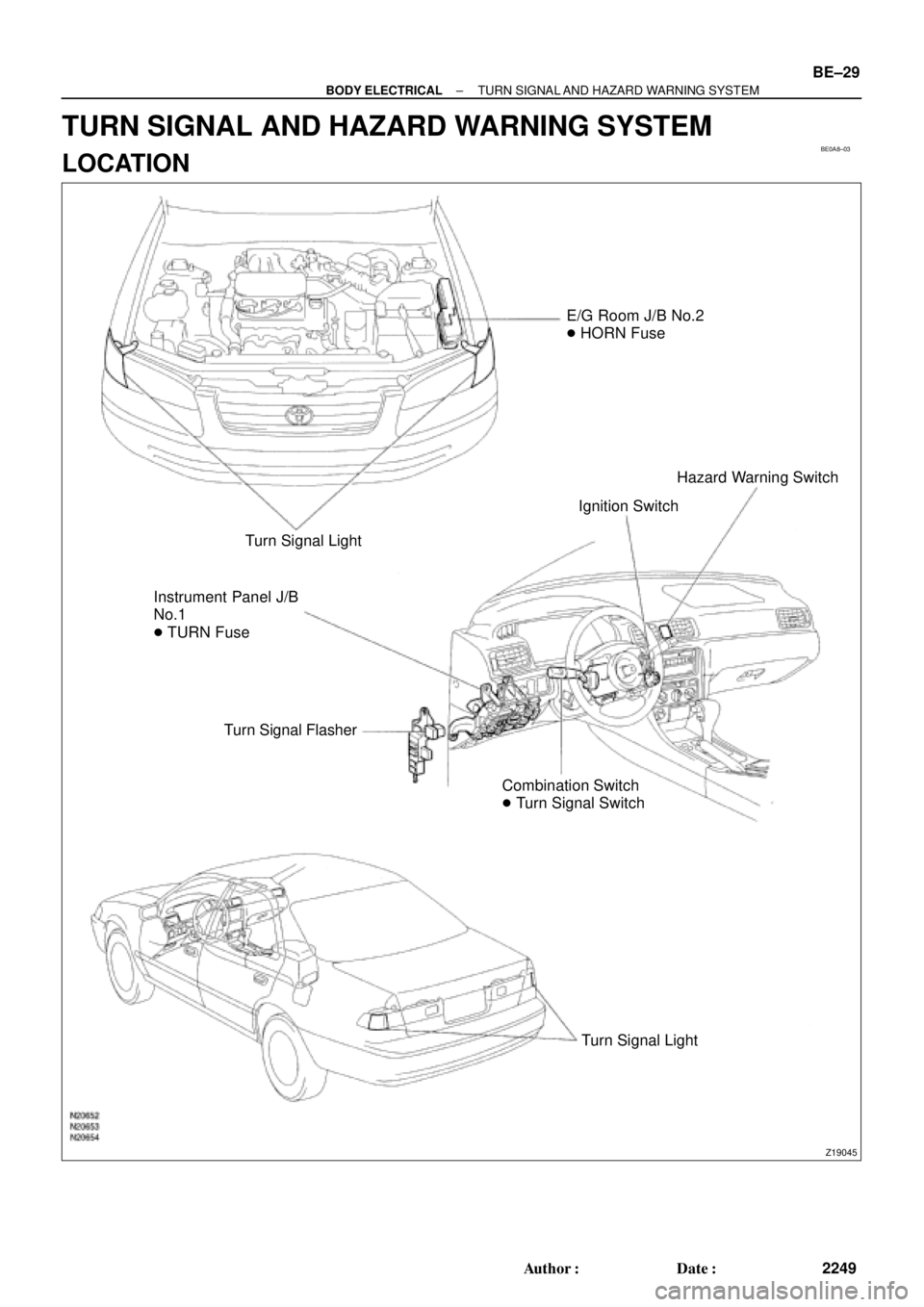
E/G Room J/B No.2
� HORN Fuse
Turn Signal Light
Instrument Panel J/B
No.1
� TURN Fuse
Turn Signal Flasher
Combination Switch
� Turn Signal SwitchIgnition SwitchHazard Warning Switch
Turn Signal Light
± BODY ELECTRICALTURN SIGNAL AND HAZARD WARNING SYSTEM
BE±29
2249 Author�: Date�:
TURN SIGNAL AND HAZARD WARNING SYSTEM
LOCATION
Page 2128 of 4770
BE0AC±02
Z19047
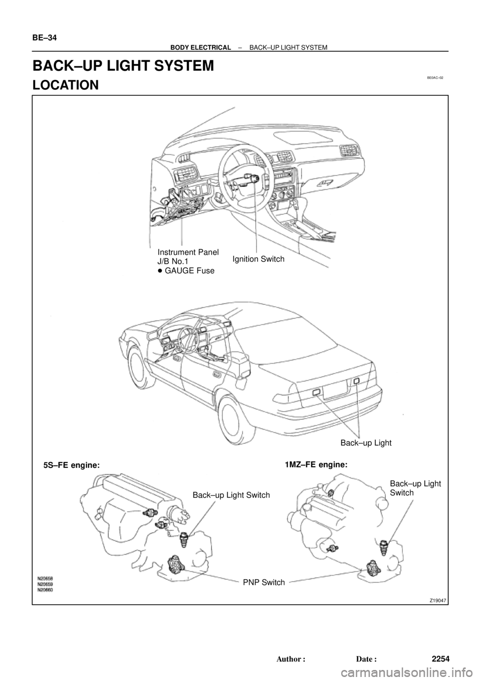
Instrument Panel
J/B No.1
� GAUGE FuseIgnition Switch
Back±up Light
Back±up Light SwitchBack±up Light
Switch
PNP Switch 5S±FE engine:1MZ±FE engine: BE±34
± BODY ELECTRICALBACK±UP LIGHT SYSTEM
2254 Author�: Date�:
BACK±UP LIGHT SYSTEM
LOCATION
Page 2132 of 4770

N20209
Wire harness side:
1 2 3 4 5
6 7 8 9 10 11 12
e±12±2±B
BE±38
± BODY ELECTRICALSTOP LIGHT SYSTEM
2258 Author�: Date�:
4. INSPECT LIGHT FAILURE RELAY CIRCUIT
Disconnect the connector from the relay and inspect the con-
nector on the wire harness side, as shown.
Tester connectionConditionSpecified condition
1 ± GroundConstantContinuity*
2 ± GroundConstantContinuity*
9 ± GroundConstantContinuity*
11 ± GroundConstantContinuity
3 ± GroundLight control switch OFFNo voltage
3 ± GroundLight control switch TAIL or HEADBattery positive voltage
4 ± GroundIgnition switch LOCK or ACCNo voltage
4 ± GroundIgnition switch ONBattery positive voltage
7 ± GroundStop light switch OFFNo voltage
7 ± GroundStop light switch ONBattery positive voltage
8 ± GroundIgnition switch LOCK or ACCNo voltage
8 ± GroundIgnition switch ONBattery positive voltage
*: There is resistance because this circuit is grounded through
the bulb.
If the circuit is as specified, replace the relay.
If the circuit is not as specified, inspect the circuits connected
to other parts.
Page 2142 of 4770
 Compare the")
N20160
Ignition
Switch
Fuel
Gauge
Battery
Z05727
Ignition
SwitchFuel
Gauge
Battery
Ie±5±1±A BE1206123
45
N20212
A
B
C BE±48
± BODY ELECTRICALCOMBINATION METER
2268 Author�: Date�:
(b) Compare the tester with tachometer indications.
DC 13.5 V 25°C at (77 °F)
Standard indicationAllowable range
700630 ± 770
1,000900 ± 1,100
2,0001,850 ± 2,150
3,0002,800 ± 3,200
4,0003,800 ± 4,200
5,0004,800 ± 5,200
6,0005,750 ± 6,250
7,0006,700 ± 7,300
4. INSPECT FUEL RECEIVER GAUGE OPERATION
(a) Disconnect the connector from the sender gauge.
(b) Turn the ignition switch ON, check that the receiver gauge
needle indicates EMPTY.
(c) Connect terminals 2 and 3 on the wire harness side con-
nector through a 3.4±W test bulb.
(d) Turn the ignition switch ON, check that the bulb lights up
and the receiver gauge needle moves towards the full
side.
HINT:
Because of the silicon oil in the gauge, it will take a short time
for needle to stabilize.
If operation is not as specified, inspect the receiver gauge resis-
tance.
5. INSPECT FUEL RECEIVER GAUGE RESISTANCE
Measure the resistance between terminals.
Tester connectionResistance (W)
A ± BApprox. 126.2
A ± CApprox. 280.5
B ± CApprox. 154.3
If resistance value is not as specified, replace the receiver
gauge.
Page 2143 of 4770

N20161
F
1/2
E1
2 3
Z05730 1
3
42
5
BE1217 Ie±5±1±A
BatteryWarning Light
Ignition
Switch
N20213
1 3
N20214
1
3
N20215
Engine coolant temperature gauge
Ignition
Switch
BatterySender
Gauge
± BODY ELECTRICALCOMBINATION METER
BE±49
2269 Author�: Date�:
6. INSPECT FUEL SENDER GAUGE RESISTANCE
Measure the resistance between terminals 2 and 3 for each
float position.
Float position mm (in.)Resistance (W)
F: Approx. ±91.1 (±3.587)Approx. 3.0
1/2: Approx. ±34.2 (±1.346)Approx. 31.7
E: Approx. 30.8 (1.213)Approx. 110.0
If resistance value is not as specified, replace the sender
gauge.
7. INSPECT FUEL LEVEL WARNING LIGHT
(a) Disconnect the connector from the sender gauge.
(b) Connect terminals 1 and 3 on the wire harness side con-
nector.
(c) Turn the ignition switch ON, check that the warning light
lights up.
If the warning light does not light up, test the bulb or inspect wire
harness.
8. INSPECT FUEL LEVEL WARNING SWITCH
(a) Apply battery positive voltage between terminals 1 and 3
through a 3.4±W test bulb, check that the bulb lights up.
HINT:
It takes a short time for the bulb to light up.
(b) Submerge the switch in fuel, check that the bulb goes out.
If operation is not as specified, replace the sender gauge.
9. INSPECT ENGINE COOLANT TEMPERATURE RE-
CEIVER GAUGE OPERATION
(a) Disconnect the connector from the sender gauge.
(b) Turn the ignition switch ON and check that the receiver
gauge needle indicates COOL.