Page 2161 of 4770
 Close(c) Open
A3 Type B:
± BODY ELECTRICALPOWER WINDOW CONTROL SYSTEM
BE±67
2287 Author�: Date�:
(f) Approximately 60 seconds later, connect the positive")
I21313
2
1
I12561
2
1
I12560
21
N20564
(b) Close(c) Open
A3 Type B:
± BODY ELECTRICALPOWER WINDOW CONTROL SYSTEM
BE±67
2287 Author�: Date�:
(f) Approximately 60 seconds later, connect the positive (+)
lead from the battery to terminal 1 and the negative (±)
lead to terminal 2, and check that the window begins to
descend.
If operation is not as specified, replace the motor.
13. Rear Door:
INSPECT POWER WINDOW MOTOR PTC THERM-
ISTOR OPERATION
(a) Disconnect the connector from the power window switch.
(b) Connect the positive (+) lead from the ammeter to termi-
nal 1 on the wire harness side connector and the negative
(±) lead to negative terminal of the battery.
(c) Connect the positive (+) lead from the battery to terminal
2 on the wire harness side connector, and raise the win-
dow to the fully position.
(d) Continue to apply voltage and check that the current
changes to less than 1 A within 4 to 90 seconds.
(e) Disconnect the leads from the terminals.
(f) Approximately 60 seconds later, connect the positive (+)
lead from the battery to terminal 2 and the negative (±)
lead to terminal 1, and check that the window begins to
descend.
If operation is not as specified, replace the motor.
14. Key±off power window signal:
INSPECT INTEGRATION RELAY (TYPE B) OPERA-
TION
HINT:
When the relay circuit is as specified, inspect the key±off power
window signal.
(a) Connect the positive (+) lead from the voltmeter to termi-
nal A3 and the negative (±) lead to body ground.
(b) Close the door with ignition switch turned to LOCK or
ACC, and check that the meter needle indicates battery
positive voltage.
(c) Open the door and check that the meter needle indicates
0 V.
Page 2162 of 4770
 Close (c) Open
A12 Type C:
N20567
A12 Type C: BE±68
± BODY ELECTRICALPOWER WINDOW CONTROL SYSTEM
2288 Author�: MH Date�: 3/7/02
(d) Turn the ignition switch ON and check")
N20565
A3 Type B:
N20566
(b) Close (c) Open
A12 Type C:
N20567
A12 Type C: BE±68
± BODY ELECTRICALPOWER WINDOW CONTROL SYSTEM
2288 Author�: MH Date�: 3/7/02
(d) Turn the ignition switch ON and check that the meter
needle indicates battery positive voltage again.
If operation is not as specified, replace the relay.
15. Key±off power window signal:
INSPECT INTEGRATION RELAY (TYPE C) OPERA-
TION
HINT:
When the relay circuit is as specified, inspect the key±off power
window signal.
(a) Connect the positive (+) lead from the voltmeter to termi-
nal A12 and the negative (±) lead to body ground.
(b) Close the door with ignition switch turned to LOCK or
ACC, and check that the meter needle indicates battery
positive voltage.
(c) Open the door and check that the meter needle indicates
0 V.
(d) Turn the ignition switch ON and check that the meter
needle indicates battery positive voltage again.
If operation is not as specified, replace the relay.
16. INSPECT INTEGRATION RELAY CIRCUIT
(See page XX±XXX)
Page 2167 of 4770
BE0AR±02
Z19490
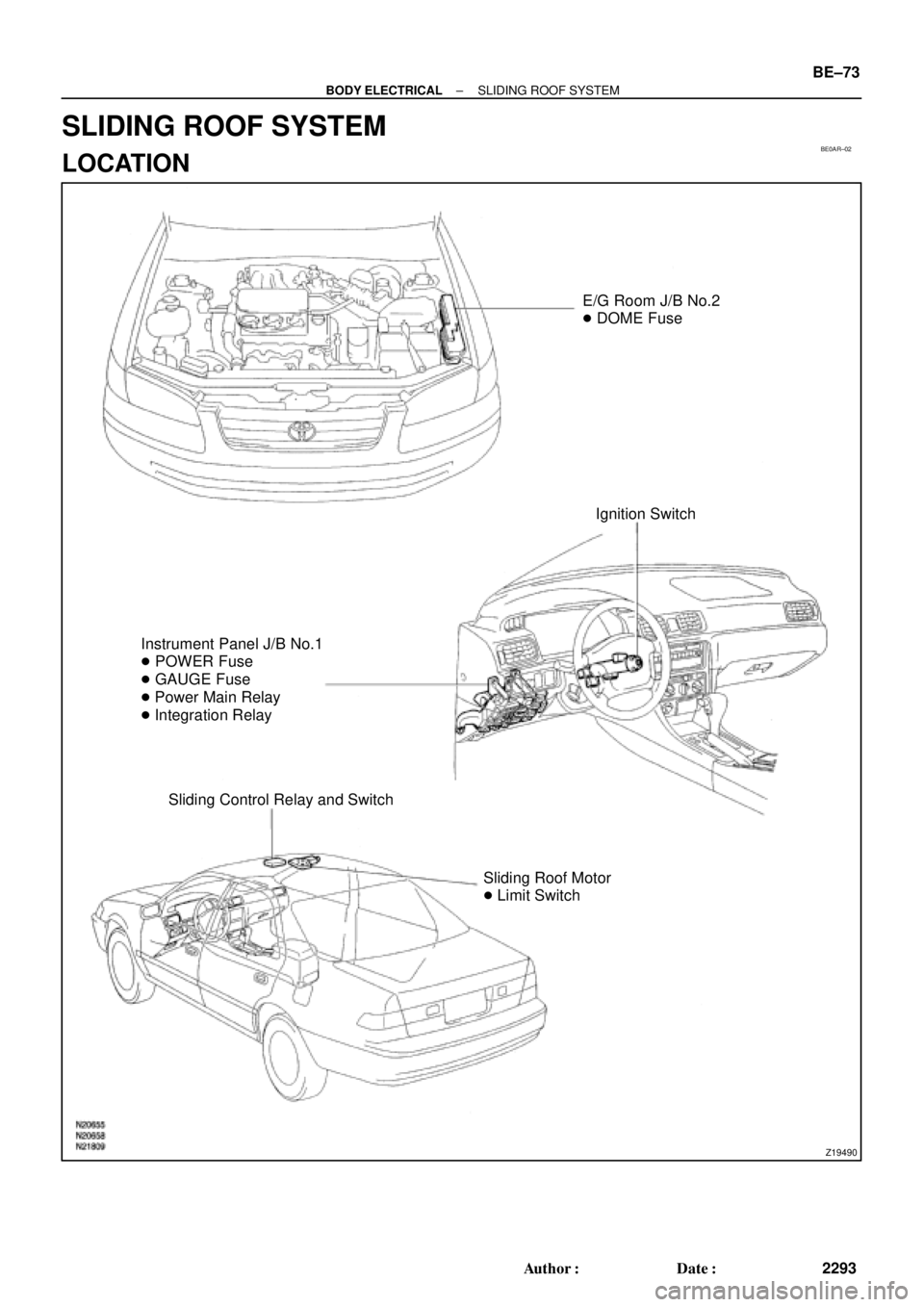
E/G Room J/B No.2
� DOME Fuse
Ignition Switch
Instrument Panel J/B No.1
� POWER Fuse
� GAUGE Fuse
� Power Main Relay
� Integration Relay
Sliding Control Relay and Switch
Sliding Roof Motor
� Limit Switch
± BODY ELECTRICALSLIDING ROOF SYSTEM
BE±73
2293 Author�: Date�:
SLIDING ROOF SYSTEM
LOCATION
Page 2168 of 4770

BE0AS±02
N21643
Wire harness side:
12 3
4567 8
s±8±1
BE±74
± BODY ELECTRICALSLIDING ROOF SYSTEM
2294 Author�: Date�:
INSPECTION
1. INSPECT SLIDING ROOF CONTROL RELAY AND
SWITCH CIRCUIT
Disconnect the connector from the relay and switch and inspect
the connector on the wire harness side, as shown in the table.
TMMK made:
Tester connectionConditionSpecified condition
1 ± 5ConstantContinuity
2 ± GroundConstantContinuity
3 ± GroundLimit switch No.1 is OFF (Sliding roof is in a
closed position)No continuity
3 ± GroundLimit switch No.1 is ON (Sliding roof is in an open
position)Continuity
7 ± GroundLimit switch No.2 is OFF (Sliding roof is in a tilt
up position)No continuity
7 ± GroundLimit switch No.2 is ON (Sliding roof is in the
open position)Continuity
8 ± GroundLimit switch No.3 is OFF (Sliding roof is in a
closed position)No continuity
8 ± GroundLimit switch No.3 is ON (Sliding roof is in an open
position)Continuity
4 ± GroundIgnition switch is in a LOCK or ACC position* No voltage
4 ± GroundIgnition switch is in an ON positionBattery positive voltage
TMC made:
Tester connectionConditionSpecified condition
1 ± 5ConstantContinuity
2 ± GroundConstantContinuity
3 ± GroundNo.1 limit switch OFF (Sliding roof closed)No continuity
3 ± GroundNo.1 limit switch ON (Sliding roof opened)Continuity
7 ± GroundNo.2 limit switch OFF (Sliding roof tilted up open
approx. 200 mm (7.87 in.)No continuity
7 ± GroundNo.2 limit switch ON (Except for conditions
mentioned above)Continuity
4 ± GroundIgnition switch LOCK or ACC* No voltage
4 ± GroundIgnition switch ONBattery positive voltage
*: Exceptions: For 60 seconds after the ignition switch is turned
ON to OFF (ACC) or until driver or passenger door is opened
after the ignition switch is turned ON to OFF (ACC).
If the circuit is not as specified, replace the relay and switch.
Page 2207 of 4770

I01475
25 Noise NOISE PRODUCED WHEN ENGINE STARTS
Whistling noise which becomes high±pitched when
accelerator strongly depressed, disappears shortly
after engine stops.Generator noise.
Whining noise occurs when A/C is operating. A/C noise.
Scratching noise occurs during sudden acceleration,
driving on rough roads or when ignition switch is turned
on.Fuel gauge noise.
Clicking sound heard when horn button is pressed,
then released. Whirring/ grating sound when pressed
continuously.Horn noise.
Murmuring sound stops when engine stops. Ignition noise.Ye s
No
No
No
No
NoYe s
Ye s
Ye s
Ye s
Tick±tock noise occurs in co±ordination with
blinking of flasher.
Noise occurs during window washer operation. Washer noise.Turn signal noise.
No
NoYe s
Ye s
Scratching noise occurs while engine is running
and continues for a while even after engine stops.
Scraping noise in time with wiper beat.Engine coolant temp. gauge noise.
Wiper noise.
Other type of noise.No
NoYe s
Ye s
± BODY ELECTRICALAUDIO SYSTEM
BE±113
2333 Author�: Date�:
Page 2295 of 4770
CHARGING SYSTEM
CH±1
1748 Author�: Date�:
CHARGING SYSTEM
ON±VEHICLE INSPECTION
CAUTI")
CH02U±01
Z11577
Except Maintenance±Free Battery
Z11556
Maintenance±Free Battery
Voltmeter
± CHARGING (5S±FE)CHARGING SYSTEM
CH±1
1748 Author�: Date�:
CHARGING SYSTEM
ON±VEHICLE INSPECTION
CAUTION:
�Check that the battery cables are connected to the
correct terminals.
�Disconnect the battery cables when the battery is giv-
en a quick charge.
�Do not perform tests with a high voltage insulation re-
sistance tester.
�Never disconnect the battery while the engine is run-
ning.
1. CHECK BATTERY ELECTROLYTE LEVEL
Check the electrolyte quantity of each cell.
Maintenance±Free Battery:
If under the lower level, replace the battery (or add distilled wa-
ter if possible). Check the charging system.
Except Maintenance±Free Battery:
If under the lower level, add distilled water.
2. Except Maintenance±Free Battery:
CHECK BATTERY SPECIFIC GRAVITY
Check the specific gravity of each cell.
Standard specific gravity:
1.25 ± 1.29 at 20°C (68°F)
If the specific gravity is less than specification, charge the bat-
tery.
3. Maintenance±Free Battery:
CHECK BATTERY VOLTAGE
(a) After having driven the vehicle and in the case that 20
minutes have not passed after having stopped the en-
gine, turn the ignition switch ON and turn on the electrical
system (headlight, blower motor, rear defogger etc.) for
60 seconds to remove the surface charge.
(b) Turn the ignition switch OFF and turn off the electrical sys-
tems.
(c) Measure the battery voltage between the negative (±)
and positive (+) terminals of the battery.
Standard voltage: 12.5 ± 12.9 V at 20°C (68°F)
If the voltage is less than specification, charge the battery.
Page 2297 of 4770
CHARGING SYSTEM
CH±3
1750 Author�: Date�: �
After installing a new belt, run the engine for about 5 min")
Z03473
BatteryVoltmeter
Generator Ammeter
Disconnect Wire
from Terminal B
B
± CHARGING (5S±FE)CHARGING SYSTEM
CH±3
1750 Author�: Date�: �
After installing a new belt, run the engine for about 5 min-
utes and recheck the belt tension.
6. VISUALLY CHECK GENERATOR WIRING AND
LISTEN FOR ABNORMAL NOISES
(a) Check that the wiring is in good condition.
(b) Check that there is no abnormal noise from the generator
while the engine is running.
7. CHECK CHARGE WARNING LIGHT CIRCUIT
(a) Warm up the engine and then turn it off.
(b) Turn off all accessories.
(c) Turn the ignition switch ºONº. Check that the charge warn-
ing light is lit.
(d) Start the engine. Check that the light goes off.
If the light does not go off as specified, troubleshoot the charge
light circuit.
8. INSPECT CHARGING CIRCUIT WITHOUT LOAD
HINT:
If a battery/generator tester is available, connect the tester to
the charging circuit as per manufacturer's instructions.
(a) If a tester is not available, connect a voltmeter and amme-
ter to the charging circuit as follows:
(1) Disconnect the wire from terminal B of the genera-
tor, and connect it to the negative (±) tester probe
of the ammeter.
(2) Connect the positive (+) tester probe of the amme-
ter to terminal B of the generator.
(3) Connect the positive (+) tester probe of the voltme-
ter to terminal B of the generator.
(4) Ground the negative (±) tester probe of the voltme-
ter.
(b) Check the charging circuit as follows:
With the engine running from idling to 2,000 rpm, check
the reading on the ammeter and voltmeter.
Standard amperage: 10 A or less
Standard voltage: 13.5 ± 15.1 V
If the voltmeter reading is more than standard voltage, replace
the voltage regulator.
Page 2311 of 4770
CHARGING SYSTEM
CH±1
1764 Author�: Date�:
CHARGING SYSTEM
ON±VEHICLE INSPECTION
CAUTI")
CH01D±01
Z11577
Except Maintenance±Free Battery
Z11556
Maintenance±Free BatteryVoltmeter
± CHARGING (1MZ±FE)CHARGING SYSTEM
CH±1
1764 Author�: Date�:
CHARGING SYSTEM
ON±VEHICLE INSPECTION
CAUTION:
�Check that the battery cables are connected to the
correct terminals.
�Disconnect the battery cables when the battery is
given a quick charge.
�Do not perform tests with a high voltage insulation
resistance tester.
�Never disconnect the battery while the engine is
running.
1. CHECK BATTERY ELECTROLYTE LEVEL
Check the electrolyte quantity of each cell.
(1) Maintenance±Free Battery:
If under the lower level, replace the battery (or add
distilled water if possible). Check the charging sys-
tem.
(2) Except Maintenance±Free Battery:
If under the lower level, add distilled water.
2. Except Maintenance±Free Battery:
CHECK BATTERY SPECIFIC GRAVITY
Check the specific gravity of each cell.
Standard specific gravity: 1.25 ± 1.29 at 20°C (68°F)
If the specific gravity is less than specification, charge the bat-
tery.
3. Maintenance±Free Battery:
CHECK BATTERY VOLTAGE
(a) After having driven the vehicle and in the case that 20
minutes have not passed after having stopped the en-
gine, turn the ignition switch ON and turn on the electrical
system (headlight, blower motor, rear defogger etc.) for
60 seconds to remove the surface charge.
(b) Turn the ignition switch OFF and turn off the electrical sys-
tems.
(c) Measure the battery voltage between the negative (±)
and positive (+) terminals of the battery.
Standard voltage: 12.5 ± 12.9 V at 20°C (68°F)
If the voltage is less than specification, charge the battery.