Page 2268 of 4770

2. REMOVE REAR DISC BRAKE ASSEMBLY")
BR0B9±03
W03265
R00309
BR3948
R00310
BR±46
± BRAKEPARKING BRAKE
2069 Author�: Date�:
DISASSEMBLY
1. REMOVE REAR WHEEL
Torque: 103 N´m (1.050 kgf´cm, 76 ft´lbf)
2. REMOVE REAR DISC BRAKE ASSEMBLY
(a) Remove the 2 mounting bolts and remove the disc brake
assembly.
Torque: 47 N´m (475 kgf´cm, 34 ft´lbf)
(b) Suspend the disc brake securely. Ensure that the hose is
not stretched.
3. REMOVE DISC
Release the parking brake lever and remove the disc.
HINT:
If the disc cannot be removed easily, turn the shoe adjuster until
the wheel turns freely.
4. REMOVE SHOE RETURN SPRINGS
Using needle±nose pliers, remove the shoe return springs.
5. REMOVE FRONT SHOE ADJUSTER AND TENSION
SPRING
(a) Slide out the front shoe and remove the shoe adjuster.
(b) Remove the shoe strut with the spring.
(c) Remove the shoe hold±down spring cups, spring and pin.
(d) Disconnect the tension spring and remove the front shoe.
6. REMOVE REAR SHOE
(a) Slide out the rear shoe.
(b) Remove the tension spring from the rear shoe.
(c) Remove the shoe hold±down spring cups, spring and pin.
(d) Using needle±nose pliers, disconnect the parking brake
cable from the parking brake shoe lever.
Page 2278 of 4770
BR0BH±03
W03327
Holder
Cushion
CushionA/C Tube Clamp Bracket ABS Actuator
(w/ ECU)
Actuator Bracket
N´m (kgf´cm, ft´lbf): Specified torque
9.0 (92, 80 in.´lbf)
15 (155, 11)
19 (195, 14)
19 (195, 14)
F07215
Actuator ECU
� Non±reusable part
N´m (kgf´cm, ft´lbf): Specified torque�
2.6 (27, 23 in.´lbf)
BR±56
± BRAKEABS ACTUATOR (BOSCH Made)
2079 Author�: Date�:
ABS ACTUATOR (BOSCH Made)
COMPONENTS
Page 2280 of 4770
BR0BJ±02
W03326
BR±58
± BRAKEABS ACTUATOR (BOSCH Made)
2081 Author�: Date�:
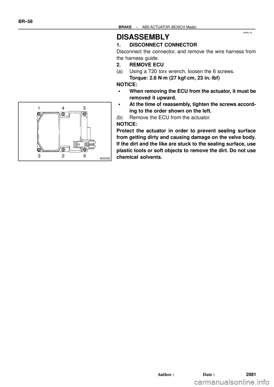
DISASSEMBLY
1. DISCONNECT CONNECTOR
Disconnect the connector, and remove the wire harness from
the harness guide.
2. REMOVE ECU
(a) Using a T20 torx wrench, loosen the 6 screws.
Torque: 2.6 N´m (27 kgf´cm, 23 in.´lbf)
NOTICE:
�When removing the ECU from the actuator, it must be
removed it upward.
�At the time of reassembly, tighten the screws accord-
ing to the order shown on the left.
(b) Remove the ECU from the actuator.
NOTICE:
Protect the actuator in order to prevent sealing surface
from getting dirty and causing damage on the valve body.
If the dirt and the like are stuck to the sealing surface, use
plastic tools or soft objects to remove the dirt. Do not use
chemical solvents.
Page 2301 of 4770
CH02X±01
Z18635
Z18636
B02378
P13597SST (B)
SST (A) Turn
P10834
SST (B)
SST (C)
Insert
± CHARGING (5S±FE)GENERATOR
CH±7
1754 Author�: Date�:
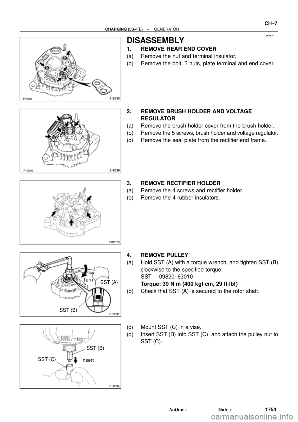
DISASSEMBLY
1. REMOVE REAR END COVER
(a) Remove the nut and terminal insulator.
(b) Remove the bolt, 3 nuts, plate terminal and end cover.
2. REMOVE BRUSH HOLDER AND VOLTAGE
REGULATOR
(a) Remove the brush holder cover from the brush holder.
(b) Remove the 5 screws, brush holder and voltage regulator.
(c) Remove the seal plate from the rectifier end frame.
3. REMOVE RECTIFIER HOLDER
(a) Remove the 4 screws and rectifier holder.
(b) Remove the 4 rubber insulators.
4. REMOVE PULLEY
(a) Hold SST (A) with a torque wrench, and tighten SST (B)
clockwise to the specified torque.
SST 09820±63010
Torque: 39 N´m (400 kgf´cm, 29 ft´lbf)
(b) Check that SST (A) is secured to the rotor shaft.
(c) Mount SST (C) in a vise.
(d) Insert SST (B) into SST (C), and attach the pulley nut to
SST (C).
Page 2307 of 4770
CH030±01
P01364
Pulley
Z18637
P13487
29 mm
Socket
Wrench
Z19213
A B
AA
P13597
SST (A) Turn
SST (B)
± CHARGING (5S±FE)GENERATOR
CH±13
1760 Author�: Date�:
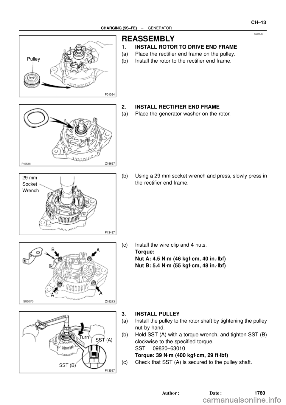
REASSEMBLY
1. INSTALL ROTOR TO DRIVE END FRAME
(a) Place the rectifier end frame on the pulley.
(b) Install the rotor to the rectifier end frame.
2. INSTALL RECTIFIER END FRAME
(a) Place the generator washer on the rotor.
(b) Using a 29 mm socket wrench and press, slowly press in
the rectifier end frame.
(c) Install the wire clip and 4 nuts.
Torque:
Nut A: 4.5 N´m (46 kgf´cm, 40 in.´lbf)
Nut B: 5.4 N´m (55 kgf´cm, 48 in.´lbf)
3. INSTALL PULLEY
(a) Install the pulley to the rotor shaft by tightening the pulley
nut by hand.
(b) Hold SST (A) with a torque wrench, and tighten SST (B)
clockwise to the specified torque.
SST 09820±63010
Torque: 39 N´m (400 kgf´cm, 29 ft´lbf)
(c) Check that SST (A) is secured to the pulley shaft.
Page 2317 of 4770
CH01G±01
P14233
Plate Terminal
P14234
S05072
P10835
SST (B)SST (A) Turn
P10834
SST (C)SST (B)
Insert
± CHARGING (1MZ±FE)GENERATOR
CH±7
1770 Author�: Date�:
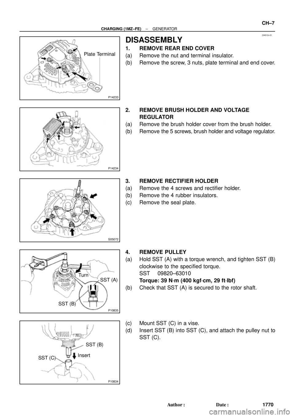
DISASSEMBLY
1. REMOVE REAR END COVER
(a) Remove the nut and terminal insulator.
(b) Remove the screw, 3 nuts, plate terminal and end cover.
2. REMOVE BRUSH HOLDER AND VOLTAGE
REGULATOR
(a) Remove the brush holder cover from the brush holder.
(b) Remove the 5 screws, brush holder and voltage regulator.
3. REMOVE RECTIFIER HOLDER
(a) Remove the 4 screws and rectifier holder.
(b) Remove the 4 rubber insulators.
(c) Remove the seal plate.
4. REMOVE PULLEY
(a) Hold SST (A) with a torque wrench, and tighten SST (B)
clockwise to the specified torque.
SST 09820±63010
Torque: 39 N´m (400 kgf´cm, 29 ft´lbf)
(b) Check that SST (A) is secured to the rotor shaft.
(c) Mount SST (C) in a vise.
(d) Insert SST (B) into SST (C), and attach the pulley nut to
SST (C).
Page 2323 of 4770
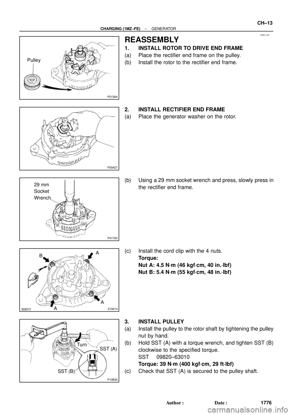
CH01J±01
P01364
Pulley
P00427
P01763
29 mm
Socket
Wrench
Z19214AA A
B
P10835
Turn
SST (A)
SST (B)
± CHARGING (1MZ±FE)GENERATOR
CH±13
1776 Author�: Date�:
REASSEMBLY
1. INSTALL ROTOR TO DRIVE END FRAME
(a) Place the rectifier end frame on the pulley.
(b) Install the rotor to the rectifier end frame.
2. INSTALL RECTIFIER END FRAME
(a) Place the generator washer on the rotor.
(b) Using a 29 mm socket wrench and press, slowly press in
the rectifier end frame.
(c) Install the cord clip with the 4 nuts.
Torque:
Nut A: 4.5 N´m (46 kgf´cm, 40 in.´lbf)
Nut B: 5.4 N´m (55 kgf´cm, 48 in.´lbf)
3. INSTALL PULLEY
(a) Install the pulley to the rotor shaft by tightening the pulley
nut by hand.
(b) Hold SST (A) with a torque wrench, and tighten SST (B)
clockwise to the specified torque.
SST 09820±63010
Torque: 39 N´m (400 kgf´cm, 29 ft´lbf)
(c) Check that SST (A) is secured to the pulley shaft.
Page 2423 of 4770

DI±3
238 Author�: Date�:
PRE±CHECK
1. DIAGNOSIS SYSTEM
(a) Description
�When troubleshooting OBD II vehicles, the")
DI00H±08
FI0534
S05331
TOYOTA Hand±Held Tester
DLC3
± DIAGNOSTICSENGINE (5S±FE)
DI±3
238 Author�: Date�:
PRE±CHECK
1. DIAGNOSIS SYSTEM
(a) Description
�When troubleshooting OBD II vehicles, the only dif-
ference from the usual troubleshooting procedure
is that you connect to the vehicle the OBD II scan
tool complying with SAE J1978 or TOYOTA hand±
held tester, and read off various data output from
the vehicle's ECM.
�OBD II regulations require that the vehicle's on±
board computer lights up the Malfunction Indicator
Lamp (MIL) on the instrument panel when the com-
puter detects a malfunction in the emission control
system / components or in the powertrain control
components which affect vehicle emissions, or a
malfunction in the computer. In addition to the MIL
lighting up when a malfunction is detected, the ap-
plicable Diagnostic Trouble Code (DTC) prescribed
by SAE J2012 are recorded in the ECM memory.
(See page DI±16)
If the malfunction does not reoccur in 3 consecutive trips, the
MIL goes off automarially but the DTCs remain recorded in the
ECM memory.
�To check the DTCs, connect the OBD II scan tool or
TOYOTA hand±held tester to Data Link Connector
3 (DLC3) on the vehicle. The OBD II scan tool or
TOYOTA hand±held tester also enables you to
erase the DTCs and check freezed frame data and
various forms of engine data (For operating instruc-
tions, see the OBD II scan tool's instruction book.)
DTCs include SAE controlled codes and manufac-
turer controlled codes. SAE controlled codes must
be set as prescribed by the SAE, while manufactur-
er controlled codes can be set freely by the
manufacturer within the prescribed limits. (See DTC
chart on page DI±16)

Actuator Bracket
N´m (kgf´cm, ft´lbf): Specified torque
9.0 (92, 80 in.´lbf)
15 (155, 11)
19 (195, 14)
19 (195,")