Page 2219 of 4770

4. Remove the mast")
1. Insert master key in the key cylinder.
2. Depress and release the acceleration pedal 6 times.
3. Depress and release the brake pedal 7 times.
(Security indicator blinks)
4. Remove the master key.
(Security indicator blinks)
HINT:
When the key cannot be pulled out in the step 4, key code deletion is canceled.
(Security indicator is OFF) END
(Key code erasured)
Within 15 sec.
Within 20 sec.
Within 10 sec.
± BODY ELECTRICALENGINE IMMOBILISER SYSTEM
BE±125
2345 Author�: Date�:
4. ERASURE OF TRANSPONDER KEY CODE
There are 2 ways for erasure of transponder key code, one is depressing brake pedal and acceleration pedal
and the other is using TOYOTA hand±held tester.
NOTICE:
All other master and sub±key codes are deleted leaving the master key code to use the operation.
When using the key which was used before deleting, it is necessary to register the code again.
HINT:
�When any operation time described below is over, registration mode completes.
�When the next procedure is performed while the timer is working, the timer completes counting time,
then next timer starts.
(1) Depressing brake pedal and acceleration pedal:
Page 2220 of 4770
1. Insert master key in the key cylinder.
2. Require key code deletion from hand±held tester.
(Security indicator blinks)
3. Remove the master key.
HINT:
When the key cannot be pulled out in the step 3, key code deletion is canceled.
(Security indicator is OFF) END
(Key code erasured)
Within 120 sec.
Within 10 sec.
BE±126
± BODY ELECTRICALENGINE IMMOBILISER SYSTEM
2346 Author�: Date�:
(2) Using TOYOTA hand±held tester:
Page 2229 of 4770
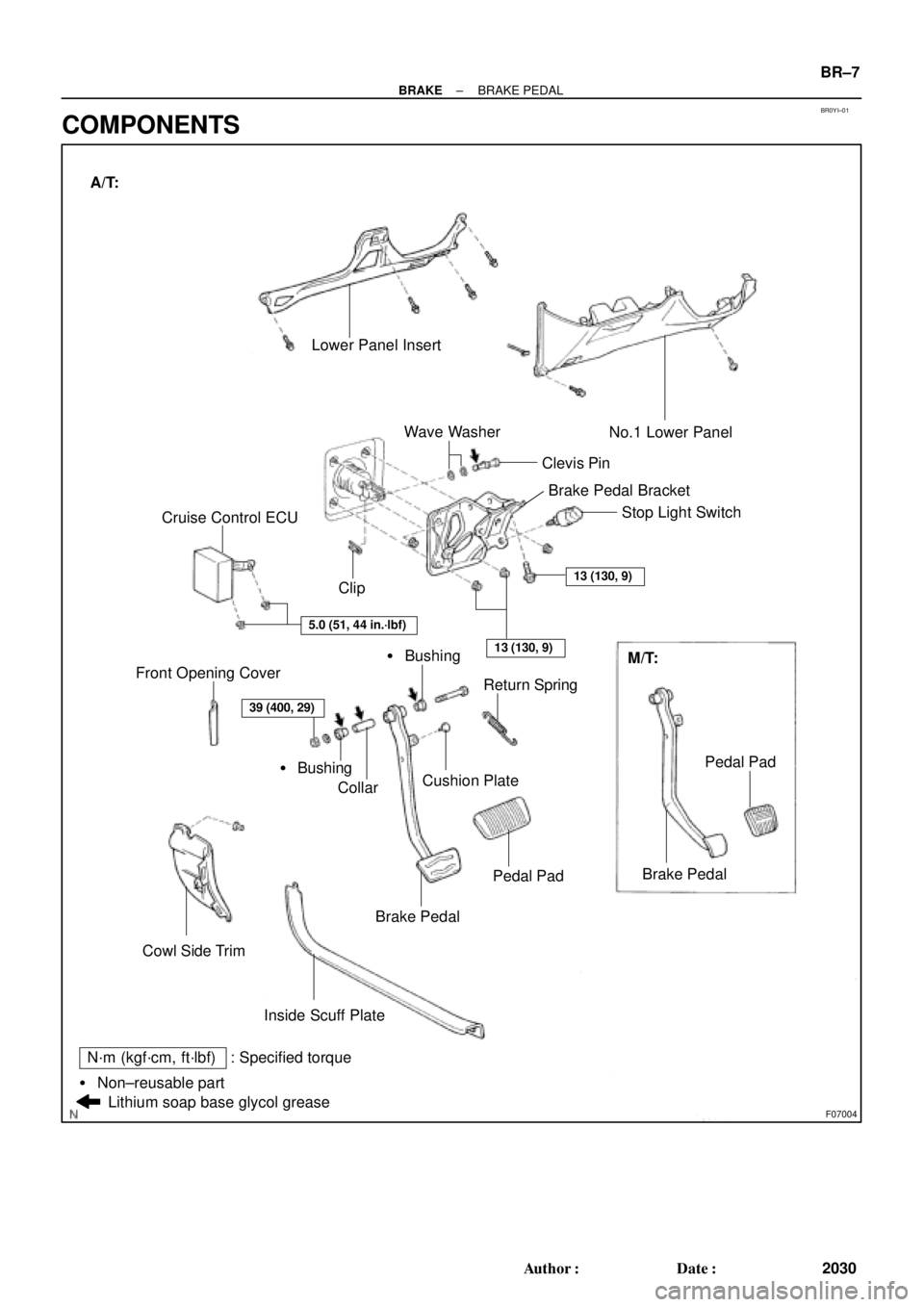
BR0YI±01
F07004
Lower Panel Insert
� Bushing ClipClevis PinNo.1 Lower Panel
Return Spring
Cushion Plate
Collar
Brake Pedal
Cowl Side Trim Front Opening Cover
Brake Pedal
Inside Scuff PlateM/T: Stop Light Switch
Wave Washer
Cruise Control ECU
Lithium soap base glycol grease
13 (130, 9)
5.0 (51, 44 in.´lbf)
13 (130, 9)
Pedal Pad
Pedal Pad� Bushing A/T:
39 (400, 29)
: Specified torqueN´m (kgf´cm, ft´lbf)
� Non±reusable partBrake Pedal Bracket
± BRAKEBRAKE PEDAL
BR±7
2030 Author�: Date�:
COMPONENTS
Page 2244 of 4770

BR0AP±03
F07213
R02874
BR±22
± BRAKEFRONT BRAKE PAD
2045 Author�: Date�:
REPLACEMENT
1. REMOVE FRONT WHEEL
Remove the wheel and temporarily fasten the disc with hub
nuts.
2. INSPECT PAD LINING THICKNESS
Check the pad thickness through the caliper inspection hole
and replace the pads if they are not within the specification.
Minimum thickness: 1.0 mm (0.039 in.)
3. LIFT UP CALIPER
(a) Remove the bolt and flexible hose from the bracket.
(b) 5S±FE engine:
Hold the sliding pin on the bottom and loosen the installa-
tion bolt, and remove the installation bolt.
(c) 1MZ±FE engine:
Remove the bottom side installation bolt.
(d) Lift up the caliper and suspend it securely.
HINT:
Do not disconnect the flexible hose from the caliper.
4. 5S±FE engine:
REMOVE 2 ANTI±SQUEAL SPRINGS
5. REMOVE 2 BRAKE PADS
6. REMOVE 4 ANTI±SQUEAL SHIMS
7. 1MZ±FE engine:
REMOVE PAD WEAR INDICATOR PLATE
8. 1MZ±FE engine:
REMOVE 2 PAD SUPPORT PLATES
9. 5S±FE engine:
REMOVE 4 PAD SUPPORT PLATES
NOTICE:
The anti±squeal springs and support plates can be used
again provided that they have sufficient rebound, no de-
formation, cracks or wear, and have had all rust, dirt and
foreign particles cleaned off.
10. CHECK DISC THICKNESS AND RUNOUT
(See page BR±28)
11. INSTALL 2 OR 4 PAD SUPPORT PLATES
12. INSTALL NEW PADS
NOTICE:
When replacing worn pads, the anti±squeal shims and
wear indicator plates must be replaced together with the
pads.
Page 2248 of 4770
BR0AR±03
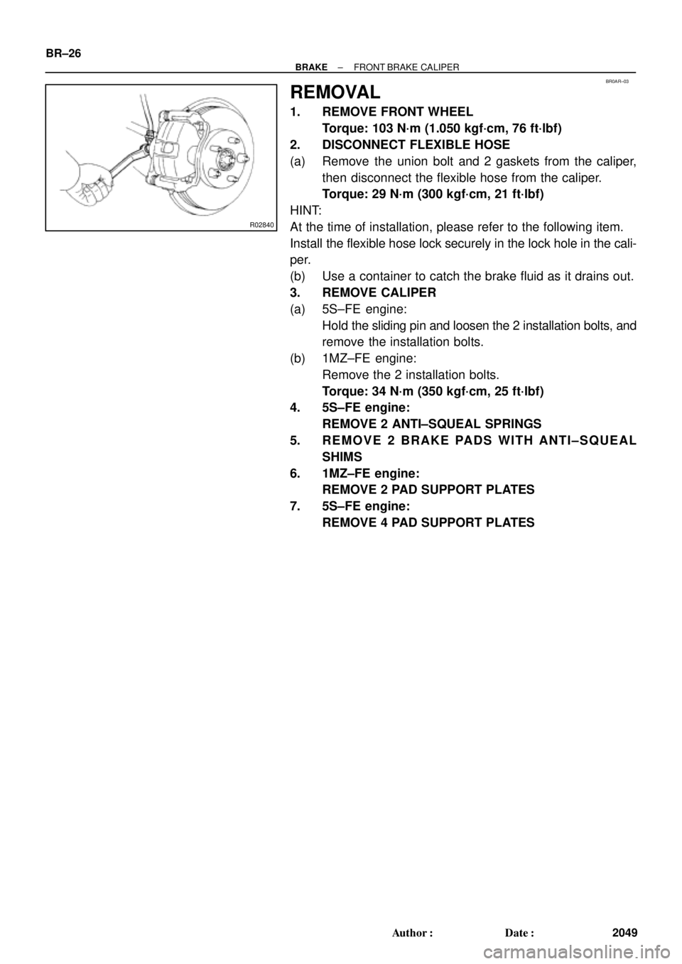
R02840
BR±26
± BRAKEFRONT BRAKE CALIPER
2049 Author�: Date�:
REMOVAL
1. REMOVE FRONT WHEEL
Torque: 103 N´m (1.050 kgf´cm, 76 ft´lbf)
2. DISCONNECT FLEXIBLE HOSE
(a) Remove the union bolt and 2 gaskets from the caliper,
then disconnect the flexible hose from the caliper.
Torque: 29 N´m (300 kgf´cm, 21 ft´lbf)
HINT:
At the time of installation, please refer to the following item.
Install the flexible hose lock securely in the lock hole in the cali-
per.
(b) Use a container to catch the brake fluid as it drains out.
3. REMOVE CALIPER
(a) 5S±FE engine:
Hold the sliding pin and loosen the 2 installation bolts, and
remove the installation bolts.
(b) 1MZ±FE engine:
Remove the 2 installation bolts.
Torque: 34 N´m (350 kgf´cm, 25 ft´lbf)
4. 5S±FE engine:
REMOVE 2 ANTI±SQUEAL SPRINGS
5. REMOVE 2 BRAKE PADS WITH ANTI±SQUEAL
SHIMS
6. 1MZ±FE engine:
REMOVE 2 PAD SUPPORT PLATES
7. 5S±FE engine:
REMOVE 4 PAD SUPPORT PLATES
Page 2259 of 4770

BR0B1±03
R00591
R00514
R10387
± BRAKEREAR BRAKE PAD
BR±37
2060 Author�: Date�:
REPLACEMENT
1. REMOVE REAR WHEEL
Remove the wheel and temporarily fasten the disc with the hub
nuts.
2. INSPECT PAD LINING THICKNESS
Check the pad thickness through the caliper inspection hole
and replace pads if not within specification.
Minimum thickness: 1.0 mm (0.039 in.)
3. LIFT UP CALIPER
(a) Remove the bolt and flexible hose from the bracket.
(b) Remove the installation bolt from the torque plate.
(c) Lift up the caliper and suspend it securely.
HINT:
Do not disconnect the flexible hose.
4. REMOVE 2 BRAKE PADS
5. REMOVE 4 ANTI±SQUEAL SHIMS
6. REMOVE 4 PAD SUPPORT PLATES
NOTICE:
The support plates can be used again provided that they
have sufficient rebound, no deformation, cracks or wear,
and have had all rust, dirt and foreign particles cleaned off.
7. CHECK DISC THICKNESS AND RUNOUT
(See page BR±42)
8. INSTALL 4 PAD SUPPORT PLATES
9. INSTALL NEW PADS
NOTICE:
When replacing worn pads, the anti±squeal shims must be
replaced together with the pads.
(a) Apply disc brake grease to both side of the inner anti±
squeal shims (See page BR±36).
(b) Install the 2 anti±squeal shims on each pad.
(c) Install 2 pads with the pad wear indicator plate facing up-
ward.
NOTICE:
There should be no oil or grease adhering to the friction
surfaces of the pads or the disc.
10. INSTALL CALIPER
(a) Draw out a small amount of brake fluid from the reservoir.
(b) Press in the piston with a hammer handle or similar imple-
ment.
HINT:
If the piston is difficult to push in, loosen the bleeder plug and
push in the piston while letting some brake fluid escape.
(c) Install the caliper and torque the installation bolt.
Torque: 20 N´m (200 kgf´cm, 14 ft´lbf)
(d) Install the flexible hose and bolt to the bracket.
Torque: 29 N´m (300 kgf´cm, 21 ft´lbf)
Page 2262 of 4770

2. DISCONNECT FLEXIBLE HOSE
(a) Remove the unio")
BR0B3±03
W03263
W03264
BR±40
± BRAKEREAR BRAKE CALIPER
2063 Author�: Date�:
REMOVAL
1. REMOVE REAR WHEEL
Torque: 103 N´m (1.050 kgf´cm, 76 ft´lbf)
2. DISCONNECT FLEXIBLE HOSE
(a) Remove the union bolt and 2 gaskets from the caliper,
then disconnect the flexible hose from the caliper.
Torque: 29 N´m (300 kgf´cm, 21 ft´lbf)
HINT:
At the time of installation, please refer to the following item.
Insert the flexible hose lock securely in the lock hole in the cali-
per.
(b) Use a container to catch the brake fluid as it drains out.
3. REMOVE CALIPER
(a) Remove the installation bolt.
Torque: 20 N´m (200 kgf´cm, 14 ft´lbf)
(b) Remove the caliper from the torque plate.
4. REMOVE 2 BRAKE PADS WITH 4 ANTI±SQUEAL
SHIMS
5. REMOVE 4 PAD SUPPORT PLATES
NOTICE:
At the time of installation, please refer to the following item.
There should be no oil or grease adhering to the friction
surfaces of the pads or disc.
6. REMOVE MAIN PIN
Loosen the main pin installation bolt and remove the main pin.
Torque: 26 N´m (270 kgf´cm, 20 ft´lbf)
Page 2263 of 4770
BR0B4±02
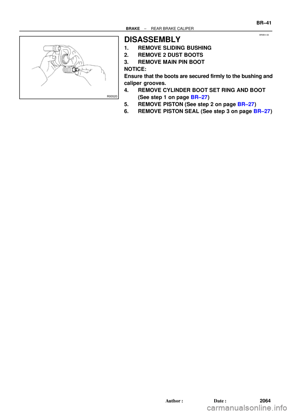
R00520
± BRAKEREAR BRAKE CALIPER
BR±41
2064 Author�: Date�:
DISASSEMBLY
1. REMOVE SLIDING BUSHING
2. REMOVE 2 DUST BOOTS
3. REMOVE MAIN PIN BOOT
NOTICE:
Ensure that the boots are secured firmly to the bushing and
caliper grooves.
4. REMOVE CYLINDER BOOT SET RING AND BOOT
(See step 1 on page BR±27)
5. REMOVE PISTON (See step 2 on page BR±27)
6. REMOVE PISTON SEAL (See step 3 on page BR±27)

3. Remove the master key.
HINT:
When the key cannot be pulled out in")