Page 2057 of 4770
H01871
± BODYFRONT SEAT (Power Seat for TMMK Made)
BO±97
2445 Author�: Date�:
6. INSTALL SEATBACK ASSEMBLY
(a) Install the seatback assembly with 4 bolts.
HINT:
Tighten the 4 bolts temporarily, then from the bolt on the front
right side tighten completely.
(b) Install Front Seatback hinge cover with bolts.
(c) Install a new hog rings.
HINT:
Install the hog rings to prevent wrinkles as least as possible.
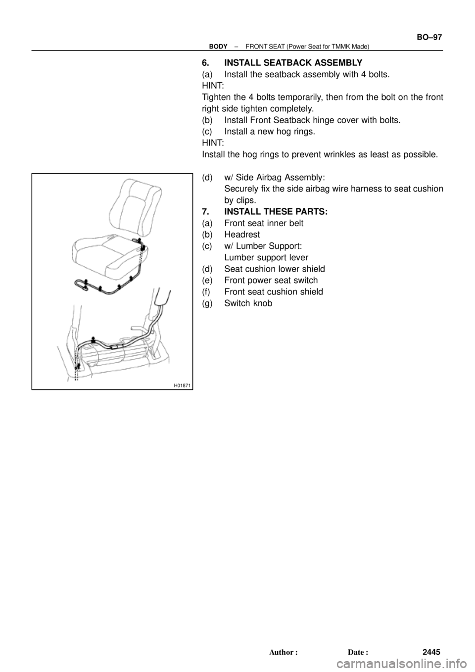
(d) w/ Side Airbag Assembly:
Securely fix the side airbag wire harness to seat cushion
by clips.
7. INSTALL THESE PARTS:
(a) Front seat inner belt
(b) Headrest
(c) w/ Lumber Support:
Lumber support lever
(d) Seat cushion lower shield
(e) Front power seat switch
(f) Front seat cushion shield
(g) Switch knob
Page 2064 of 4770
H01870
BO±104
± BODYFRONT SEAT (Manual Seat for TMC Made)
2452 Author�: Date�:
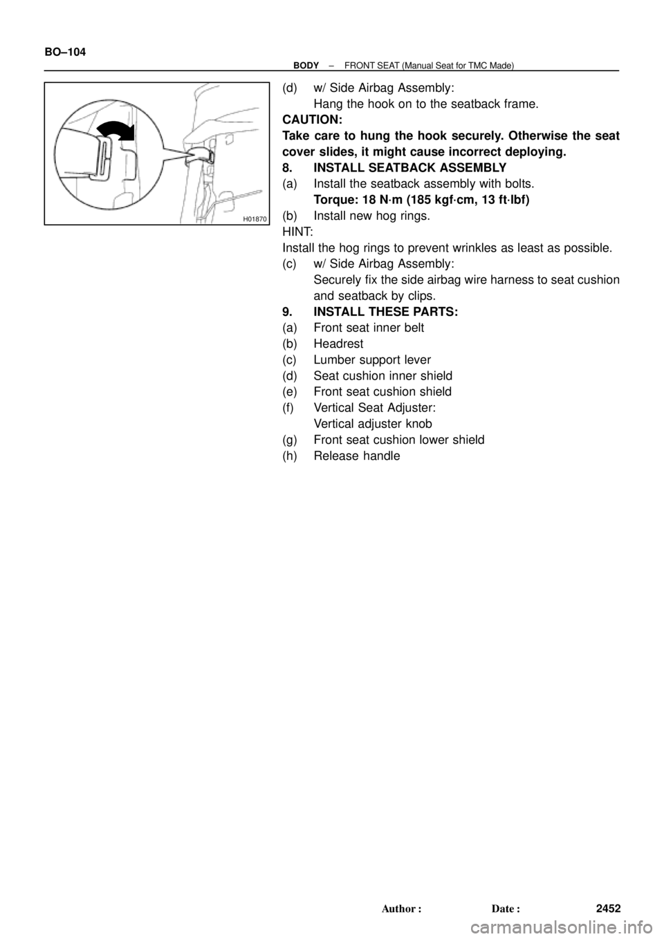
(d) w/ Side Airbag Assembly:
Hang the hook on to the seatback frame.
CAUTION:
Take care to hung the hook securely. Otherwise the seat
cover slides, it might cause incorrect deploying.
8. INSTALL SEATBACK ASSEMBLY
(a) Install the seatback assembly with bolts.
Torque: 18 N´m (185 kgf´cm, 13 ft´lbf)
(b) Install new hog rings.
HINT:
Install the hog rings to prevent wrinkles as least as possible.
(c) w/ Side Airbag Assembly:
Securely fix the side airbag wire harness to seat cushion
and seatback by clips.
9. INSTALL THESE PARTS:
(a) Front seat inner belt
(b) Headrest
(c) Lumber support lever
(d) Seat cushion inner shield
(e) Front seat cushion shield
(f) Vertical Seat Adjuster:
Vertical adjuster knob
(g) Front seat cushion lower shield
(h) Release handle
Page 2071 of 4770
H01870
H01871
± BODYFRONT SEAT (Manual Seat for TMMK Made)
BO±111
2459 Author�: Date�:
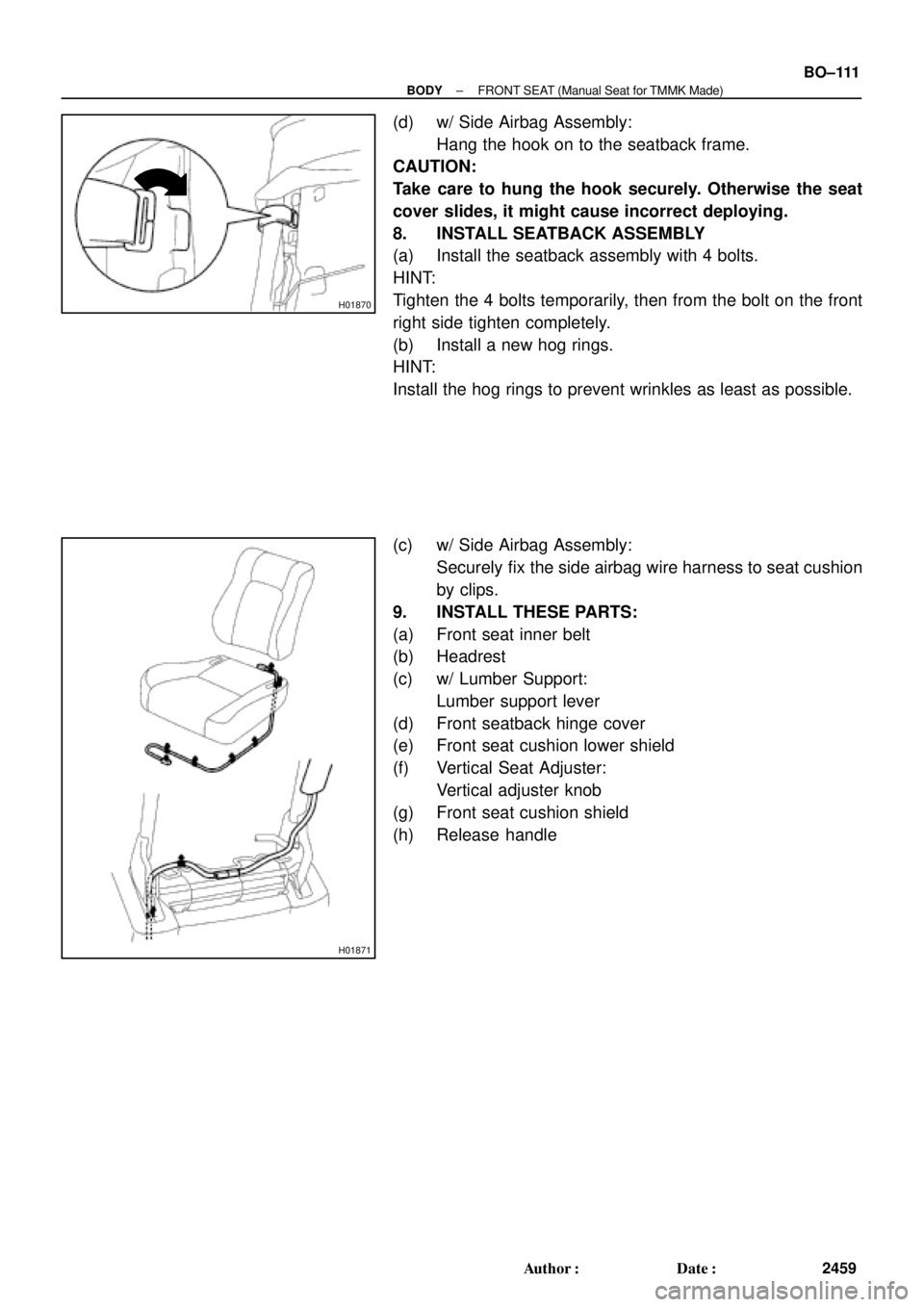
(d) w/ Side Airbag Assembly:
Hang the hook on to the seatback frame.
CAUTION:
Take care to hung the hook securely. Otherwise the seat
cover slides, it might cause incorrect deploying.
8. INSTALL SEATBACK ASSEMBLY
(a) Install the seatback assembly with 4 bolts.
HINT:
Tighten the 4 bolts temporarily, then from the bolt on the front
right side tighten completely.
(b) Install a new hog rings.
HINT:
Install the hog rings to prevent wrinkles as least as possible.
(c) w/ Side Airbag Assembly:
Securely fix the side airbag wire harness to seat cushion
by clips.
9. INSTALL THESE PARTS:
(a) Front seat inner belt
(b) Headrest
(c) w/ Lumber Support:
Lumber support lever
(d) Front seatback hinge cover
(e) Front seat cushion lower shield
(f) Vertical Seat Adjuster:
Vertical adjuster knob
(g) Front seat cushion shield
(h) Release handle
Page 2097 of 4770

SymptomSuspect AreaSee page
Headlight does not light.
(Taillight is normal)1. Wire Harness±")
± BODY ELECTRICALBODY ELECTRICAL SYSTEM
BE±3
2223 Author�: Date�:
HEADLIGHT AND TAILLIGHT SYSTEM (CANADA)
SymptomSuspect AreaSee page
Headlight does not light.
(Taillight is normal)1. Wire Harness±
Headlight does not light.
(Taillight does not light up)1. Wire Harness±
Only one side light does not light.
1. Headlight Bulb
2. HEAD LO (LH, RH) Fuse (E/G Room R/B No.2)
3. Wire Harness±
±
±
ºLo±Beamº does not light.
1. Headlight Bulb
2. HEAD LO (LH, RH) Fuse (E/G Room R/B No.2)
3. Headlight Control Relay (E/G Room J/B No.2)
4. Integration Relay (I/P J/B No.1)
5. Light Control Switch
6. Wire Harness±
±
BE±24
BE±14
BE±24
±
ºHi±Beamº does not light.
1. Headlight Bulb
2. ECU±B Fuse (E/G Room J/B No.2)
3. HEAD HI (LH, RH) Fuse (E/G Room J/B No.2)
4. DRL Fuse (E/G Room R/B No.2)
5. Daytime Running Light Relay No.2
(E/G Room R/B No.2)
6. Daytime Running Light Relay No.3
(E/G Room R/B No.2)
7. Daytime Running Light Relay No.4
(E/G Room R/B No.2)
8. Daytime Running Light Relay (Main)
9. Headlight Dimmer Switch
10.Wire Harness±
±
±
±
±
BE±24
±
BE±24
±
BE±24
BE±24
BE±24
±
ºFlashº does not light.
1. Headlight Bulb
2. ECU±B Fuse (E/G Room J/B No.2)
3. HEAD HI (LH, RH) Fuse (E/G Room J/B No.2)
4. DRL Fuse (E/G Room R/B No.2)
5. Daytime Running Light Relay No.2
(E/G Room R/B No.2)
6. Daytime Running Light Relay No.3
(E/G Room R/B No.2)
7. Daytime Running Light Relay No.4
(E/G Room R/B No.2)
8. Daytime Running Light Relay (Main)
9. Headlight Dimmer Switch
10.Wire Harness±
±
±
±
±
BE±24
±
BE±24
±
BE±24
BE±24
BE±24
±
ºAuto Turn±off Systemº does not operate.
1. GAUGE Fuse (I/P J/B No.1)
2. DOME Fuse (E/G Room J/B No.2)
3. Integration Relay (I/P J/B No.2)
4. Door Courtesy Switch (Driver's)
5. Ignition Switch
6. Wire Harness±
±
BE±14
BE±24
BE±14
±
Headlight does not light with engine running and light control SW
OFF.
1. Headlight Bulb
2. ECU±B Fuse (E/G Room J/B No.2)
3. GAUGE Fuse (I/P J/B No.1)
4. HEAD HI (LH, RH) Fuse (E/G Room J/B No.2)
5. Daytime Running Light Relay (Main)
6. Wire Harness
7. Other Parts*±
±
±
±
BE±24
±
±
Page 2100 of 4770

BE±6
± BODY ELECTRICALBODY ELECTRICAL SYSTEM
2226 Author�: Date�:
Washer fluid does not operate.1. Washer Hose and Nozzle±
� In wiper switch HI position, the wiper blade is in contact with
the body.
� When the wiper switch is OFF, the wiper blade does not
retract or the retract position is wrong.1. *1Wiper Switch
2. Wire HarnessBE±40
±
COMBINATION METER
METER, GAUGES AND ILLUMINATION:
SymptomSuspect AreaSee page
Tachometer, Fuel Gauge and Engine Coolant Temperature Gauge
do not operate.1. GAUGE Fuse (I/P J/B No.1)
2. Meter Circuit Plate
3. Wire Harness±
BE±46
±
Speedometer does not operate.
1. No.1 Vehicle Speed Sensor
2. Meter Circuit Plate
3. Wire HarnessBE±47
BE±46
±
Tachometer does not operate.
1. Igniter (5S±FE)
(1MZ±FE)
2. Meter Circuit Plate
3. Wire HarnessIG±1
IG±1
BE±46
±
Fuel Gauge does not operate or abnormal operation.
1. Fuel Receiver Gauge
2. Fuel Sender Gauge
3. Meter Circuit Plate
4. Wire HarnessBE±47
BE±47
BE±46
±
Engine Coolant Temperature Gauge does not operate or abnormal
operation
1. Engine Coolant Temperature Receiver Gauge
2. Engine Coolant Temperature Sender Gauge
3. Meter Circuit Plate
4. Wire HarnessBE±47
BE±47
BE±46
±
All illumination lights do not light up.
1. TAIL Fuse (I/P J/B No.1)
2. Light Control Rheostat
3. Wire Harness±
BE±47
±
Brightness does not change even when rheostat turned.1. Bulb
2. Wire Harness±
±
Only one illumination light does not light up.1. Bulb
2. Wire Harness±
±
COMBINATION METER
WARNING LIGHTS:
SymptomSuspect AreaSee page
Warning lights do not light up. (Except Discharge, Open Door and
SRS)1. GAUGE Fuse (I/P J/B No.1)
2. Meter Circuit Plate
3. Wire Harness±
BE±46
±
Low Oil Pressure warning light does not light up.
1. Bulb
2. Low Oil Pressure Warning Switch
3. Meter Circuit Plate
4. Wire Harness±
BE±47
BE±46
±
Fuel Level warning light does not light up.
1. Bulb
2. Fuel Level Warning Switch
3. Meter Circuit Plate
4. Wire Harness±
BE±47
BE±46
±
ABS warning light does not light up.
1. Bulb
2. ABS ECU
3. Wire Harness±
IN±31
±
Page 2101 of 4770

4. Wire Harness±")
± BODY ELECTRICALBODY ELECTRICAL SYSTEM
BE±7
2227 Author�: Date�:
Seat Belt warning light does not light up.
1. Bulb
2. Seat Belt Buckle Switch
3. Integration Relay (I/P J/B No.1)
4. Wire Harness±
BE±47
BE±47
±
Discharge warning light does not light up.
1. IGN Fuse (I/P J/B No.1)
2. Bulb
3. Wire Harness
4. Generator (5S±FE)
(1MZ±FE)±
±
±
CH±1
CH±1
Light Failure warning light does not light up.
1. Bulb
2. Light Failure Sensor
3. Bulb Check Relay
4. Wire Harness
5. Taillight system±
BE±37
BE±47
±
BE±24
Brake warning light does not light up.
1. Bulb
2. Parking Brake Switch
3. Brake Fluid Level Warning Switch
4. Bulb Check Relay
5. Meter Circuit Plate
6. Wire Harness±
BE±47
BE±47
BE±47
BE±46
±
SRS Warning light does not light up.
1. ECU±B Fuse (E/G Room J/B No.2)
2. Bulb
3. Airbag Sensor Assembly
4. Meter Circuit Plate
5. Wire Harness±
±
DI±626
BE±46
±
Open Door warning light does not light up.
1. DOME Fuse (E/G Room J/B No.2)
2. Bulb
3. Door Courtesy Switch
4. Meter Circuit Plate
5. Wire Harness±
±
BE±32
BE±46
±
Washer Level warning light does not light up.
1. Bulb
2. Washer Fluid Level Warning Switch
3. Meter Circuit Plate
4. Wire Harness±
BE±47
BE±46
±
COMBINATION METER
INDICATOR LIGHTS:
SymptomSuspect AreaSee page
O/D OFF indicator light does not light up.
1. Bulb
2. O/D OFF Switch (A140E)
(A541E)
3. Meter Circuit Plate
4. Wire Harness±
DI±431
DI±487
BE±46
±
Cruise Control indicator light does not light up.
1. Bulb
2. Cruise Control ECU
3. Meter Circuit Plate
4. Wire Harness±
IN±31
BE±46
±
High beam indicator light does not light up.
1. Bulb
2. Meter Circuit Plate
3. Wire Harness
4. Headlight System±
BE±46
±
BE±22
Turn indicator light does not light up.
1. Bulb
2. Meter Circuit Plate
3. Wire Harness
4. Turn Signal and Hazard Warning System±
BE±46
±
BE±29
Page 2102 of 4770

(A541E)
4. Wire Harne")
BE±8
± BODY ELECTRICALBODY ELECTRICAL SYSTEM
2228 Author�: Date�:
Shift indicator lights do not light up.
1. Bulb
2. Meter Circuit Plate
3. Park/Neutral Position Switch (A140E)
(A541E)
4. Wire Harness±
BE±46
DI±424
DI±479
±
Only one shift indicator does not light up.1. Bulb
2. Meter Circuit Plate±
BE±46
Malfunction indicator light does not light up.
1. Bulb
2. ECM
3. Meter Circuit Plate
4. Wire Harness±
±
BE±46
±
SLIP indicator light does not light up.
1. Bulb
2. Traction ECU
3. Meter Circuit Plate
4. Wire Harness±
±
BE±46
±
TRAC OFF indicator light does not light up.
1. Bulb
2. Traction ECU
3. Meter Circuit Plate
4. Wire Harness±
±
BE±46
±
Security indicator light does not light up.
1. Bulb
2. Security ECU
3. Meter Circuit Plate
4. Wire Harness±
±
BE±46
±
Indicator lights do not light up. (Except Turn, Hi±beam and
security)1. GAUGE Fuse (I/P J/B No.1)
2. Wire Harness±
±
DEFOGGER SYSTEM
SymptomSuspect AreaSee page
All defogger systems do not operate.
1. DEFOG M±Fuse (I/P J/B No.1)
2. HTR Fuse (I/P J/B No.1)
3. Defogger Relay (I/P J/B No.1)
4. Defogger Switch
5. Wire Harness±
±
BE±56
BE±56
±
Rear window defogger does not operate.
1. Defogger Wire
2. Choke Coil
3. Wire HarnessBE±56
±
±
Mirror defogger does not operate.
1. MIR/HTR Fuse (I/P J/B No.1)
2. Mirror Defogger
3. Wire Harness±
BE±56
±
POWER WINDOW CONTROL SYSTEM
SymptomSuspect AreaSee page
Power window does not operate (ALL).
(Power Door Lock does not operate)1. POWER M±Fuse (I/P J/B No.1)
2. Power Main Relay (I/P J/B No.1)
3. Wire Harness±
BE±60
±
Power window does not operate (ALL).
(Power Door Lock is normal)1. Ignition Switch
2. Power Window Master Switch
3. Wire HarnessBE±14
BE±60
±
ºOne Touch Power Window Systemº does not operate.1. Power Window Master SwitchBE±60
Only one window glass does not move.
1. Power Window Master Switch
2. Power Window Switch
3. Power Window Motor
4. Wire HarnessBE±60
BE±60
BE±60
±
ºWindow Lock Systemº does not operate.1. Power Window Master SwitchBE±60
Page 2116 of 4770
BE0A4±02
I08436
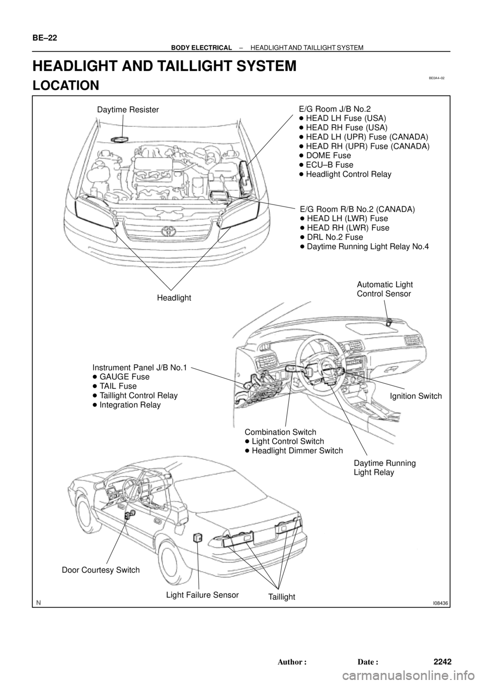
Daytime ResisterE/G Room J/B No.2
� HEAD LH Fuse (USA)
� HEAD RH Fuse (USA)
� HEAD LH (UPR) Fuse (CANADA)
� HEAD RH (UPR) Fuse (CANADA)
� DOME Fuse
� ECU±B Fuse
� Headlight Control Relay
E/G Room R/B No.2 (CANADA)
� HEAD LH (LWR) Fuse
� HEAD RH (LWR) Fuse
� DRL No.2 Fuse
� Daytime Running Light Relay No.4
Headlight
Instrument Panel J/B No.1
� GAUGE Fuse
� TAIL Fuse
� Taillight Control Relay
� Integration Relay
Daytime Running
Light RelayIgnition Switch
Combination Switch
� Light Control Switch
� Headlight Dimmer Switch
Door Courtesy Switch
Light Failure Sensor
Taillight
Automatic Light
Control Sensor
BE±22
± BODY ELECTRICALHEADLIGHT AND TAILLIGHT SYSTEM
2242 Author�: Date�:
HEADLIGHT AND TAILLIGHT SYSTEM
LOCATION