Page 1792 of 4770

IATIntake Air TemperatureIntake or Inlet Air Temperature
ICMIgnition Control Module±
IFIIndirect Fuel")
INTRODUCTIONGLOSSARY OF SAE AND TOYOTA TERMS ±
IN±7
IACIdle Air ControlIdle Speed Control (ISC)
IATIntake Air TemperatureIntake or Inlet Air Temperature
ICMIgnition Control Module±
IFIIndirect Fuel InjectionIndirect Injection
IFSInertia Fuel±Shutoff±
ISCIdle Speed Control±
KSKnock SensorKnock Sensor
MAFMass Air FlowAir Flow Meter
MAPManifold Absolute PressureManifold Pressure
Intake Vacuum
MCMixture Control
Electric Bleed Air Control Valve (EBCV)
Mixture Control Valve (MCV)
Electric Air Control Valve (EACV)
MDPManifold Differential Pressure±
MFIMultiport Fuel InjectionElectronic Fuel Injection (EFI)
MILMalfunction Indicator LampCheck Engine Light
MSTManifold Surface Temperature±
MVZManifold Vacuum Zone±
NVRAMNon±Volatile Random Access Memory±
O2SOxygen SensorOxygen Sensor, O2 Sensor (O2S)
OBDOn±Board DiagnosticOn±Board Diagnostic (OBD)
OCOxidation Catalytic ConverterOxidation Catalyst Converter (OC), CCo
OPOpen LoopOpen Loop
PAIRPulsed Secondary Air InjectionAir Suction (AS)
PCMPowertrain Control Module±
PNPPark/Neutral Position±
PROMProgrammable Read Only Memory±
PSPPower Steering Pressure±
PTOXPeriodic Trap OxidizerDiesel Particulate Filter (DPF)
Diesel Particulate Trap (DPT)
RAMRandom Access MemoryRandom Access Memory (RAM)
RMRelay Module±
ROMRead Only MemoryRead Only Memory (ROM)
RPMEngine SpeedEngine Speed
SCSuperchargerSupercharger
SCBSupercharger Bypass±
SFISequential Multiport Fuel InjectionElectronic Fuel Injection (EFI), Sequential Injection
SPLSmoke Puff Limiter±
SRIService Reminder Indicator±
SRTSystem Readiness Test±
STScan Tool±
TBThrottle BodyThrottle Body
TBIThrottle Body Fuel InjectionSingle Point Injection
Central Fuel Injection (Ci)
TCTurbochargerTurbocharger
TCCTorque Converter ClutchTorque Converter
TCMTransmission Control ModuleTransmission ECU (Electronic Control Unit)
TPThrottle PositionThrottle Position
TRTransmission Range±
Page 1878 of 4770
AUTOMATIC TRANSAXLEVALVE BODY ±
AX±82
4. PLACE UPPER VALVE BODY WITH PLATE AND GAS-
KETS ON LOWER VALVE BODY
Hold the upper valve body, plate and gaskets securely so
they do not separate.
Align each bolt hole in the valve bodies with the gaskets
and plate.
5. INSTALL AND FINGER TIGHTEN BOLTS IN UPPER
VALVE BODY TO SECURE LOWER VALVE BODY
Install and finger tighten the 3 bolts.
HINT: Each bolt length is indicated below.
Bolt length:
Bolt A: 44 mm (1.732 in.)
Bolt B: 16 mm (0.630 in.)
6. INSTALL NO.2 LOWER VALVE BODY COVER GAS-
KETS, PLATE AND 3 CHECK BALLS
(a) Install the 3 check balls into the No.2 lower valve body
cover.
Page 1946 of 4770
AX03V±01
D01027
Key Interlock Solenoid
Shift Lock Control ECU Shift Lock Override Cover
Shift Lock Control SwitchShift Lock Override Button Stop Light Switch
Shift Lock Solenoid
AX±18
± AUTOMATIC TRANSAXLE (A541E)SHIFT LOCK SYSTEM (TMMK Made)
1938 Author�: Date�:
SHIFT LOCK SYSTEM (TMMK Made)
LOCATION
Page 1947 of 4770

1 (P)
4 (KLS+) 3 (IG)
6 (STP)
5 (E)
BBack Side
Front Side A
4 (P2)
5 (SLS±)
3 (P1)
2 (SLS+)
Q09460
5 (SLS±)
2 (SLS+)
Q09461
5 (SLS±)
2 (SLS+)
± AUTOMATIC TRANSAXLE (A541E)")
AX03W±01
Q09459
1 (ACC)
1 (P)
4 (KLS+) 3 (IG)
6 (STP)
5 (E)
BBack Side
Front Side A
4 (P2)
5 (SLS±)
3 (P1)
2 (SLS+)
Q09460
5 (SLS±)
2 (SLS+)
Q09461
5 (SLS±)
2 (SLS+)
± AUTOMATIC TRANSAXLE (A541E)SHIFT LOCK SYSTEM (TMMK Made)
AX±19
1939 Author�: Date�:
INSPECTION
1. INSPECT SHIFT LOCK CONTROL ECU
Using a voltmeter, measure voltage at each terminal.
HINT:
Do not disconnect the ECU connector.
TerminalMeasuring ConditionVoltage (V)
A, 1 ± A, 5 (ACC ± E)Ignition switch ACC10 ± 14
A, 3 ± A, 5 (IG ± E)Ignition switch ON10 ± 14
A, 6 ± A, 5 (STP ± E)Depressing brake pedal10 ± 14
A, 4 ± A, 5 (KLS+ ± E)
(1) Ignition switch ACC and P position
(2) Ignition switch ACC and except P position
(3) Ignition switch ACC and except P position (After approx. 1 second)0
7.5 ± 11
6 ± 9.5
B, 2 ± B, 5 (SLS+ ± SLS±)
(1) Ignition switch ON and P position
(2) Depress brake pedal
(3) Except P position0
8 ± 13.5
0
B, 3 ± B, 1 (P1 ± P)(1) Ignition switch ON, P position and depress brake pedal
(2) Shift except P position under conditions above0
9 ± 13.5
B, 4 ± B, 1 (P2 ± P)(1) Ignition switch ACC, P position
(2) Shift except P position under conditions above9 ± 13.5
0
2. INSPECT SHIFT LOCK SOLENOID
(a) Disconnect the solenoid connector.
(b) Using an ohmmeter, measure resistance between termi-
nals.
Standard resistance: 29 ± 35 W
If resistance value is not as specified, replace the solenoid.
(c) Apply battery positive voltage between terminals. Check
that operation.
If the solenoid does not operated, replace the solenoid noise
can be heard from the solenoid.
Page 1952 of 4770
AUTOMATIC TRANSAXLE UNIT
1944 Author�: Date�:
12. REMOVE 2 FRONT SIDE ENGINE MOUNTING BOLTS
Torque:
TMC Made: 80 N´m (820 kgf´cm, 59")
Q06478
Q10286
Q06530
Q10038
AX±24
± AUTOMATIC TRANSAXLE (A541E)AUTOMATIC TRANSAXLE UNIT
1944 Author�: Date�:
12. REMOVE 2 FRONT SIDE ENGINE MOUNTING BOLTS
Torque:
TMC Made: 80 N´m (820 kgf´cm, 59 ft´lbf)
TMMK Made:
Green color bolt: 66 N´m (670 kgf´cm, 48 ft´lbf)
Silver color bolt: 44 N´m (440 kgf´cm, 32 ft´lbf)
13. REMOVE STARTER AND A/T SHIFT CABLE CLAMP
(a) Disconnect the connector and remove the nut.
(b) Remove the 2 bolts, starter and A/T shift cable clamp.
Torque: 39 N´m (400 kgf´cm, 29 ft´lbf)
14. REMOVE EXHAUST MANIFOLD BRACKET MOUNT-
ING BOLT
Torque:
Except California: 20 N´m (200 kgf´cm, 15 ft´lbf)
California: 34 N´m (350 kgf´cm, 25 ft´lbf)
15. REMOVE 5 TRANSAXLE±TO±ENGINE BOLTS AND
DISCONNECT GROUND TERMINAL
Torque: 66 N´m (670 kgf´cm, 48 ft´lbf)
16. REMOVE ENGINE HOOD
(a) Disconnect the washer pipe.
(b) Remove the 4 bolts and engine hood.
Torque: 26 N´m (265 kgf´cm, 19 ft´lbf)
17. RAISE AND SUPPORT VEHICLE SECURELY
18. REMOVE FRONT WHEELS
Torque: 103 N´m (1,050 kgf´cm, 76 ft´lbf)
19. REMOVE DIFFERENTIAL FLUID DRAIN PLUG AND
GASKET
HINT:
At the time of installation, please refer to the following item.
Replace the used gasket with a new gasket.
20. DRAIN DIFFERENTIAL FLUID
21. REMOVE LH AND RH ENGINE SIDE COVERS
22. REMOVE LH AND RH FRONT DRIVE SHAFTS
(See page SA±25)
Page 2006 of 4770
N21019
Adhesive
BO2821
BO3986
BO3671AdhesiveAdhesive
± BODYWINDSHIELD
BO±47
2395 Author�: Date�:
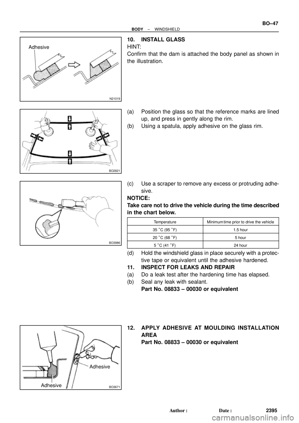
10. INSTALL GLASS
HINT:
Confirm that the dam is attached the body panel as shown in
the illustration.
(a) Position the glass so that the reference marks are lined
up, and press in gently along the rim.
(b) Using a spatula, apply adhesive on the glass rim.
(c) Use a scraper to remove any excess or protruding adhe-
sive.
NOTICE:
Take care not to drive the vehicle during the time described
in the chart below.
TemperatureMinimum time prior to drive the vehicle
35 °C (95 °F)1.5 hour
20 °C (68 °F)5 hour
5 °C (41 °F)24 hour
(d) Hold the windshield glass in place securely with a protec-
tive tape or equivalent until the adhesive hardened.
11. INSPECT FOR LEAKS AND REPAIR
(a) Do a leak test after the hardening time has elapsed.
(b) Seal any leak with sealant.
Part No. 08833 ± 00030 or equivalent
12. APPLY ADHESIVE AT MOULDING INSTALLATION
AREA
Part No. 08833 ± 00030 or equivalent
Page 2051 of 4770
H01870
± BODYFRONT SEAT (Power Seat for TMC Made)
BO±91
2439 Author�: Date�:
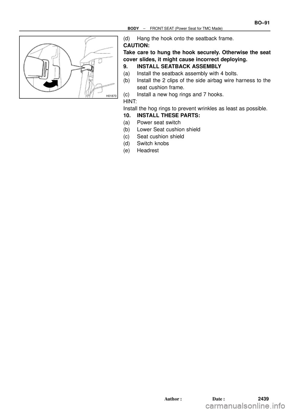
(d) Hang the hook onto the seatback frame.
CAUTION:
Take care to hung the hook securely. Otherwise the seat
cover slides, it might cause incorrect deploying.
9. INSTALL SEATBACK ASSEMBLY
(a) Install the seatback assembly with 4 bolts.
(b) Install the 2 clips of the side airbag wire harness to the
seat cushion frame.
(c) Install a new hog rings and 7 hooks.
HINT:
Install the hog rings to prevent wrinkles as least as possible.
10. INSTALL THESE PARTS:
(a) Power seat switch
(b) Lower Seat cushion shield
(c) Seat cushion shield
(d) Switch knobs
(e) Headrest
Page 2056 of 4770

2444 Author�: Date�:
REASSEMBLY
1. INSTALL THESE PARTS:
(a) Front seat cushion inner shield
(b) Front seat cushion bracket
(c) Fron")
BO0MX±01
H01870
BO±96
± BODYFRONT SEAT (Power Seat for TMMK Made)
2444 Author�: Date�:
REASSEMBLY
1. INSTALL THESE PARTS:
(a) Front seat cushion inner shield
(b) Front seat cushion bracket
(c) Front seat cushion inner No.1 shield
2. INSTALL SEAT CUSHION COVER
(a) Install the seat cushion cover to seat cushion pad.
(b) Install the seat cushion cover with pad to the seat cushion
frame.
3. INSTALL SEAT CUSHION ASSEMBLY
Install the seat cushion assembly with 4 bolts to the seat adjust-
er.
HINT:
Tighten the 4 bolts temporarily, then from the bolts on the rear
side tighten completely.
4. w/ Side Airbag Assembly:
INSTALL SIDE AIRBAG ASSEMBLY
Install the side airbag assembly with 2 nuts to the seatback
frame.
Torque: 6.0 N´m (61 kgf´cm, 53 in.´lbf)
NOTICE:
�Make sure that the side airbag assembly is installed
to the specified torque.
�If the side airbag assembly has been dropped, or
there are cracks, dents or other defects in the case or
connector, replace the side airbag assembly with a
new one.
�When installing the side airbag assembly, take care
is not pinched between other parts.
5. INSTALL SEATBACK COVER
(a) Install the seatback cover to the seatback pad.
(b) Install the seatback cover with pad to the seatback frame.
(c) Install the headrest supports.
(d) w/ Side Airbag Assembly:
Hang the hook on to the seatback frame.
CAUTION:
Take care to hung the hook securely. Otherwise the seat
cove slides, it might cause incorrect deploying.