Page 2428 of 4770

243 Author�: Date�:
4. FAIL±SAFE CHART
If any of the following codes is recorded, the ECM enters fail±safe mode.
DTC No.Fail±Safe OperationFail±Safe Deactivatio")
DI±8
± DIAGNOSTICSENGINE (5S±FE)
243 Author�: Date�:
4. FAIL±SAFE CHART
If any of the following codes is recorded, the ECM enters fail±safe mode.
DTC No.Fail±Safe OperationFail±Safe Deactivation Conditions
P0105Ignition timing fixed at 5° BTDCReturned to normal condition
P0110Intake air temperature is fixed at 20°C (68°F)Returned to normal condition
P0115Engine coolant temperature is fixed at 80°(176°F)Returned to normal condition
P0120VTA is fixed at 0°
The following condition must be repeated at least 2 times
consecutively
VTA ��0.1 V and � 0.95 V
P0135
P0141The heater circuit in witch an abnormality is detected is
turned offIgnition switch OFF
P0325Max. timing retardationIgnition switch OFF
P0336Fuel cutReturned to normal condition
P1135The heater circuit in which an abnormality is detected is
turned offIgnition switch OFF
P1300
P1310Fuel cutIGF signal is detected for 2 consecutive ignitions
5. CHECK FOR INTERMITTENT PROBLEMS
TOYOTA HAND±HELD TESTER only:
By putting the vehicle's ECM in check mode, 1 trip detection logic is possible instead of 2 trip detection logic
and sensitivity to detect open circuits is increased. This makes it easier to detect intermittent problems.
(1) Clear the DTC (See page DI±3).
(2) Set the check mode (See page DI±3).
(3) Perform a simulation test (See page IN±21).
(4) Check the connector and terminal (See page IN±31).
(5) Handle the connector (See page IN±31).
6. BASIC INSPECTION
When the malfunction code is not confirmed in the DTC check, troubleshooting should be performed in the
order for all possible circuits to be considered as the causes of the problems. In many cases, by carrying
out the basic engine check shown in the following flow chart, the location causing the problem can be found
quickly and efficiently. Therefore, use of this check is essential in engine troubleshooting.
1 Is battery positive voltage 11 V or more when engine is stopped?
NO Charge or replace battery.
YES
Page 2583 of 4770

DI±163
398 Author�: Date�:
DTC P1300 Igniter Circuit Malfunction No.1
DTC P1310 Igniter Circuit Malfunction No.2
CIRCUIT DESCRIPTION
The ECM determines the ignition timi")
± DIAGNOSTICSENGINE (5S±FE)
DI±163
398 Author�: Date�:
DTC P1300 Igniter Circuit Malfunction No.1
DTC P1310 Igniter Circuit Malfunction No.2
CIRCUIT DESCRIPTION
The ECM determines the ignition timing, turns on Tr1 at a predetermined angle (°CA) before the desired
ignition timing and outputs and ignition signal (IGT) 1 to the igniter.
Since the width of the IGT signal is constant, the dwell angle control circuit in the igniter determines the time
the control circuit starts primary current flow to the ignition coil based on the engine rpm and ignition timing
one revolution ago, that is, the time the Tr2 turns on.
When it reaches the ignition timing, the ECM turns Tr1 off and outputs the IGT signal O.
This turns Tr2 off, interrupting the primary current flow and generating a high voltage in the secondary coil
which causes the spark plug to spark. Also, by the counter electromotive force generated when the primary
current is interrupted, the igniter sends an ignition confirmation signal (IGF) to the ECM. The ECM stops fuel
injection as a fail safe function when the IGF signal is not input to the ECM.
DTC No.DTC Detecting ConditionTrouble Area
P1300No IGF signal to ECM for 4 consecutive IGT1 signals during
engine running�Open or short in IGF or IGT circuit from igniter to ECM
�Ignition coil No.1 (Igniter No.1)
�ECM
P1310No IGF signal to ECM for 4 consecutive IGT2 signals during
engine running�Open or short in IGF or IGT circuit from igniter to ECM
�Ignition coil No.2 (Igniter No.2)
�ECM
HINT:
Ignition coil No.1 is for cylinder No.1 and No.4, and ignition coil No.2 is for cylinder No.2 and No.3.
DI01G±06
Page 2617 of 4770

DI±197
432 Author�: Date�:
PRE±CHECK
1. DIAGNOSIS SYSTEM
(a) Description
�When troubleshooting OBD II vehicles, the on")
DI07A±06
FI0534
A06134
TOYOTA Hand±Held Tester
± DIAGNOSTICSENGINE (1MZ±FE)
DI±197
432 Author�: Date�:
PRE±CHECK
1. DIAGNOSIS SYSTEM
(a) Description
�When troubleshooting OBD II vehicles, the only dif-
ference from the usual troubleshooting procedure
is that you connect to the vehicle the OBD II scan
tool complying with SAE J1978 or TOYOTA hand±
held tester, and read off various data output from
the vehicle's ECM.
�OBD II regulations require that the vehicle's on±
board computer lights up the Malfunction Indicator
Lamp (MIL) on the instrument panel when the com-
puter detects a malfunction in the emission control
system/components or in the powertrain control
components which affect vehicle emissions, or a
malfunction in the computer. In addition to the MIL
lighting up when a malfunction is detected, the ap-
plicable Diagnostic Trouble Codes (DTC) pre-
scribed by SAE J2012 are recorded in the ECM
memory (See page DI±211).
If the malfunction does not reoccur in 3 consecutive trips, the
MIL goes off but the DTCs remain recorded in the ECM memory.
�To check the DTC, connect the OBD II scan tool or
TOYOTA hand±held tester to Data Link Connector
3 (DLC3) on the vehicle. The OBD II scan tool or
TOYOTA hand±held tester also enables you to
erase the DTC and check freezed frame data and
various forms of engine data (For operating instruc-
tions, see the OBD II scan tool's instruction book.).
DTC include SAE controlled codes and manufac-
turer controlled codes. SAE controlled codes must
be set as prescribed by the SAE, while manufactur-
er controlled codes can be set freely by the
manufacturer within the prescribed limits (See DTC
chart on page DI±211).
Page 2622 of 4770

437 Author�: Date�:
4. FAIL±SAFE CHART
If any of the following codes is recorded, the ECM enters fail±safe mode.
DTC No.Fail±Safe OperationFail±Safe Deactiva")
DI±202
± DIAGNOSTICSENGINE (1MZ±FE)
437 Author�: Date�:
4. FAIL±SAFE CHART
If any of the following codes is recorded, the ECM enters fail±safe mode.
DTC No.Fail±Safe OperationFail±Safe Deactivation Conditions
P0100Ignition timing fixed at 10° BTDCReturned to normal condition
P0110Intake air temperature is fixed at 20°C (68°F)Returned to normal condition
P0115Engine coolant temperature is fixed at 80°C (176°F)Returned to normal condition
P0120VTA is fixed at 0°
The following condition must be repeated at least 2 times
consecutively
(a) Vehicle speed: 0km/h (0mph)
(b) VTA ��0.1 V and � 0.95 V
P0135
P0141
P0155The heater circuit in which an abnormality is detected is
turned offIgnition switch OFF
P0325
P0330Max. timing retardationIgnition switch OFF
P1300Fuel cutIGF signal is detected for 6 consecutive ignition
5. CHECK FOR INTERMITTENT PROBLEMS
TOYOTA HAND±HELD TESTER only:
By putting the vehicle's ECM in check mode, 1 trip detection logic is possible instead of 2 trip detection logic
and sensitivity to detect open circuits is increased. This makes it easier to detect intermittent problems.
(1) Clear the DTC (See page DI±197).
(2) Set the check mode (See page DI±197).
(3) Perform a simulation test (See page IN±21).
(4) Check the connector and terminal (See page IN±31).
(5) Handle the connector (See page IN±31).
6. BASIC INSPECTION
When the malfunction code is not confirmed in the DTC check, troubleshooting should be performed in the
order for all possible circuits to be considered as the causes of the problems. In many cases, by carrying
out the basic engine check shown in the following flow chart, the location causing the problem can be found
quickly and efficiently. Therefore, use of this check is essential in engine troubleshooting.
1 Is battery positive voltage 11 V or more when engine is stopped ?
NO Charge or replace battery.
YES
Page 2771 of 4770

S00251
From BatteryIgnition Coil
Spark Plug
IGC1
IGC2
IGC3
GND TA C IGT1
IGT2
IGT3
IGF
To Tachometer ECM G
NE
Camshaft
Position
Sensor
Crankshaft
Position
Sensor
Various
SensorNo.2 Cylinder
No.1 Cylinder
No.4 Cylinder
No.3 Cylinder
No.6 Cylinder
No.5 Cylinder
± DIAGNOSTICSENGINE (1MZ±FE)
DI±351
586 Author�: Date�:
DTC P1300 Igniter Circuit Malfunction
CIRCUIT DESCRIPTION
A DIS (Direct Ignition System) has been adopted. The DIS improves the ignition timing accuracy, reduces
high±voltage loss, and enhances the overall reliability of the ignition system by eliminating the distributor.
The DIS is a 2±cylinder simultaneous ignition system which ignites 2 cylinders simultaneously with one igni-
tion coil. In the 2±cylinder simultaneous ignition system, each of the 2 spark plugs is connected to the end
of the secondary winding. High voltage generated in the secondary winding is applied directly to the spark
plugs. The sparks of the 2 spark plugs pass simultaneously from the center electrode to the ground elec-
trode.
The ECM determines ignition timing and outputs the ignition signals (IGT) for each cylinder. Based on IGT
signals, the igniter controls the primary ignition signals (IGC) for all ignition coils. At the same time, the igniter
also sends an ignition confirmation signal (IGF) as a fail±safe measure to the ECM.
DTC No.DTC Detecting ConditionTrouble Area
P1300
Condition (a) is repeated 3 times consecutively during 6
consecutively IGT signals while engine is running
(a) IGF signal is not input to ECM for 2 or more ignitions�Open or short in IGF or IGT circuit from igniter to ECM
�Igniter
�ECM
DI084±06
Page 2815 of 4770

± DIAGNOSTICSAUTOMATIC TRANSAXLE (A140E)
DI±395
630 Author�: Date�:
(c) Replace the ATF.
(1) Remove the drain plug and drain")
Q00061
AT8562
AT3417
OK if hot
Add if hot
AT4252
0 ~ 1 mm (0 ~ 0.04 in.)
± DIAGNOSTICSAUTOMATIC TRANSAXLE (A140E)
DI±395
630 Author�: Date�:
(c) Replace the ATF.
(1) Remove the drain plug and drain the fluid.
(2) Reinstall the drain plug securely.
(3) With the engine OFF add new fluid through the oil
filler pipe.
Fluid type: ATF D±II or DEXRON®III (DEXRON®II)
Capacity: 2.5 liters (2.6 US qts, 2.1 Imp. qts)
(4) Start the engine and shift the shift lever into all posi-
tions from P to L position and then shift into P posi-
tion.
(5) With the engine idling, check the fluid level. Add
fluid up to the COOL level on the dipstick.
(6) Check the fluid level is at the normal operating tem-
perature, 70 ± 80 °C (158 ± 176 °F), and add as
necessary.
NOTICE:
Do not overfill.
(d) Check the fluid leaks.
Check for leaks in the transaxle.
If there are leaks, it is necessary to repair or replace O±rings,
gasket, oil seals, plugs or other parts.
(e) Inspect and adjust the throttle cable.
(1) Check that the accelerator pedal is fully released.
(2) Check that the inner cable is not slack.
(3) Measure the distance between the outer cable end
and stopper on the cable.
Standard distance: 0 ± 1 mm (0 ± 0.04 in.)
If the distance is not standard, adjust the cable by the adjusting
nuts.
Page 2834 of 4770
D01807
W3
E4 Transaxle
Shift Solenoid
Valve No.1
Shift Solenoid
Valve No.2
*2: w/o Engine
Immobiliser SystemE4 B1V7
21
*2
E9S1
*1: w/ Engine
Immobiliser System
A L ± B
*18
6
*2*1
E9
E9E9 L ± B J25
Junction
Connector
AAS2B+
B+
Cruise Control ECUECM
D00102 Q10102D00990
w/ Engine Immobiliser System
w/o Engine Immobiliser SystemS2
S1
S1
S2
DI±414
± DIAGNOSTICSAUTOMATIC TRANSAXLE (A140E)
649 Author�: Date�:
WIRING DIAGRAM
INSPECTION PROCEDURE
1 Measure resistance between terminal S1 or S2 of ECM and body ground.
PREPARATION:
Disconnect the connector from ECM.
CHECK:
Measure resistance between terminal S1 or S2 of ECM and
body ground.
OK:
Resistance: 11 ~ 15 W
OK Check and replace the ECM.
NG
Page 2848 of 4770
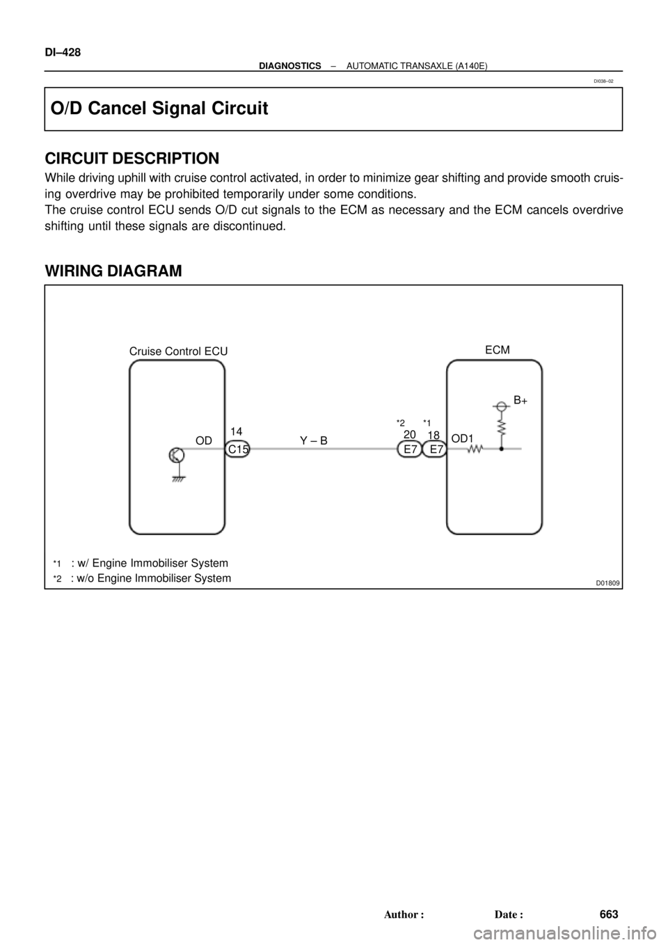
D01809
Cruise Control ECU
: w/ Engine Immobiliser System
: w/o Engine Immobiliser SystemOD14
C15Y ± B
*1
20
E7OD1B+ ECM
*2
18
E7
*1
*2
DI±428
± DIAGNOSTICSAUTOMATIC TRANSAXLE (A140E)
663 Author�: Date�:
O/D Cancel Signal Circuit
CIRCUIT DESCRIPTION
While driving uphill with cruise control activated, in order to minimize gear shifting and provide smooth cruis-
ing overdrive may be prohibited temporarily under some conditions.
The cruise control ECU sends O/D cut signals to the ECM as necessary and the ECM cancels overdrive
shifting until these signals are discontinued.
WIRING DIAGRAM
DI038±02