Page 2849 of 4770
Q07658
D00103BE3840D00995
w/ Engine Immobiliser System
w/o Engine Immobiliser SystemON
OD1
OD1 (+)
(±)
BE3840
I00143D00057
ON
OD (+) (±)
± DIAGNOSTICSAUTOMATIC TRANSAXLE (A140E)
DI±429
664 Author�: Date�:
INSPECTION PROCEDURE
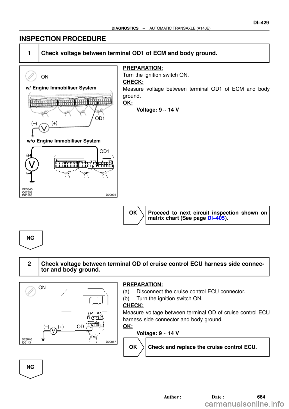
1 Check voltage between terminal OD1 of ECM and body ground.
PREPARATION:
Turn the ignition switch ON.
CHECK:
Measure voltage between terminal OD1 of ECM and body
ground.
OK:
Voltage: 9 ~ 14 V
OK Proceed to next circuit inspection shown on
matrix chart (See page DI±405).
NG
2 Check voltage between terminal OD of cruise control ECU harness side connec-
tor and body ground.
PREPARATION:
(a) Disconnect the cruise control ECU connector.
(b) Turn the ignition switch ON.
CHECK:
Measure voltage between terminal OD of cruise control ECU
harness side connector and body ground.
OK:
Voltage: 9 ~ 14 V
OK Check and replace the cruise control ECU.
NG
Page 2850 of 4770
DI±430
± DIAGNOSTICSAUTOMATIC TRANSAXLE (A140E)
665 Author�: Date�:
3 Check harness and connector between cruise control ECU and ECM.
NG Repair or replace the harness or connector.
OK
Check and replace the ECM.
Page 2864 of 4770
 DI±444
± DIAGNOSTICSAUTOMATIC TRANSAXLE (A541E)
679 Author�: Date�:
(c) Replace the ATF.
(1) Remove the drain plug and drain")
AT4657
AT8562
AT3417
OK if hot
Add if hot
AT4252
0 ~ 1 mm (0 ~ 0.04 in.) DI±444
± DIAGNOSTICSAUTOMATIC TRANSAXLE (A541E)
679 Author�: Date�:
(c) Replace the ATF.
(1) Remove the drain plug and drain the fluid.
(2) Reinstall the drain plug securely.
(3) With the engine OFF add new fluid through the oil
filler pipe.
Fluid type: ATF D±II or DEXRON®III (DEXRON®II)
Capacity: 3.9 liters (4.1 US qts, 3.4 Imp. qts)
(4) Start the engine and shift the shift lever into all posi-
tions from P to L position and then shift into P posi-
tion.
(5) With the engine idling, check the fluid level. Add
fluid up to the COOL level on the dipstick.
(6) Check the fluid level at the normal operating tem-
perature, 70 ± 80 °C (158 ± 176 °F), and add as
necessary.
NOTICE:
Do not overfill.
(d) Check the fluid leaks.
Check for leaks in the transaxle.
If there are leaks, it is necessary to repair or replace O±rings,
gasket, oil seals, plugs or other parts.
(e) Inspect and adjust the throttle cable.
(1) Check that the accelerator pedal is fully released.
(2) Check that the inner cable is not slack.
(3) Measure the distance between the outer cable end
and stopper on the cable.
Standard distance: 0 ± 1 mm (0 ± 0.04 in.)
If the distance is not the standard, adjust the cable by the ad-
justing nuts.
Page 2870 of 4770
DI02G±02
Q07932
Engine Coolant Temp. SensorCruise Control ECUThrottle Position Sensor
O/D Main Switch
O/D OFF Indicator LIght
DLC3
DLC2
Stop Light Switch
Vehicle Speed Sensor
Shift Solenoid Valve SLN
Shift Solenoid Valve No.1, No2 Shift Solenoid Valve SL
Park/Neutral Position Switch Direct Clutch Speed SensorECM
Crankshaft Position
Sensor
DI±450
± DIAGNOSTICSAUTOMATIC TRANSAXLE (A541E)
685 Author�: Date�:
PARTS LOCATION
Page 2883 of 4770
D01092
Transaxle
*1: Except California, w/ Engine Immobilizer and / or TRAC
*2: California, w/ Engine Immobilizer and / or TRACShift Solenoid
Valve No.1
W3
6 E3
L±B BV
J/C J26
A*2 *1
Shift Solenoid
Valve No.2
E3A
AL±BE11
E10 7
11
817
E10
E11 *2 *1ECM
B+
S1
S2B+
Cruise Control ECU
Q07642D00833D01909
California, w/ Engine Immobilizer
and / or TRAC:S1
S2
S1
S2
Except California, w/ Engine Immobilizer
and / or TRAC:
± DIAGNOSTICSAUTOMATIC TRANSAXLE (A541E)
DI±463
698 Author�: Date�:
WIRING DIAGRAM
INSPECTION PROCEDURE
1 Measure resistance between terminal S1 or S2 of ECM and body ground.
PREPARATION:
Disconnect the connector from ECM.
CHECK:
Measure resistance between terminal S1 or S2 of ECM and
body ground.
OK:
Resistance: 11 ~ 15 W
Page 2904 of 4770
D01899
Cruise Control ECU
14
ODY±B7B+
OD1ECM
C15
E10E7
*1: Except California, w/ Engine Immobilizer and / or TRAC
*2: California, w/ Engine Immobilizer and / or TRAC*2
*1
24 DI±484
± DIAGNOSTICSAUTOMATIC TRANSAXLE (A541E)
719 Author�: Date�:
O/D Cancel Signal Circuit
CIRCUIT DESCRIPTION
While driving uphill with cruise control activated, in order to minimize gear shifting and provide smooth cruis-
ing overdrive may be prohibited temporarily under some condition.
The cruise control ECU sends O/D cut signals to the ECM as necessary and the ECM cancels overdrive
shifting until these signals are discontinued.
WIRING DIAGRAM
DI02S±02
Page 2906 of 4770
AB0119
N19917
I00742
ON
O/D
(±)
(+)
DI±486
± DIAGNOSTICSAUTOMATIC TRANSAXLE (A541E)
721 Author�: Date�:
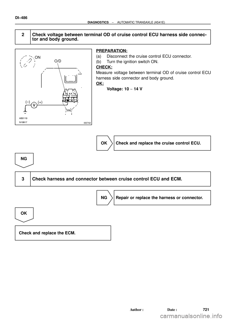
2 Check voltage between terminal OD of cruise control ECU harness side connec-
tor and body ground.
PREPARATION:
(a) Disconnect the cruise control ECU connector.
(b) Turn the ignition switch ON.
CHECK:
Measure voltage between terminal OD of cruise control ECU
harness side connector and body ground.
OK:
Voltage: 10 ~ 14 V
OK Check and replace the cruise control ECU.
NG
3 Check harness and connector between cruise control ECU and ECM.
NG Repair or replace the harness or connector.
OK
Check and replace the ECM.
Page 2914 of 4770

729 Author�: Date�:")
H07517
TOYOTA
Hand±held Tester
DLC2
BR3890
F00006DLC1Short Pin
N09348
Hand±held Tester
Break±out±boxECUTOYOTA
TOYOTA DI±494
± DIAGNOSTICSANTI±LOCK BRAKE SYSTEM (DENSO Made)
729 Author�: Date�:
(c) Using TOYOTA hand±held tester, check the DTC.
(1) Hook up the TOYOTA hand±held tester to the
DLC2.
(2) Read the DTC by following the prompts on the tes-
ter screen.
Please refer to the TOYOTA hand±held tester oper-
ator 's manual for further details.
(d) Clear the DTC.
(1) Using SST, connect terminals Tc and E
1 of DLC2 or
DLC1 and remove the short pin from DLC1.
SST 09843 ± 18020
(2) Turn the ignition switch ON.
(3) Clear the DTC stored in ECU by depressing the
brake pedal 8 or more times within 5 seconds.
(4) Check that the warning light shows the normal
code.
(5) Remove the SST from the terminals of DLC2 or
DLC1.
SST 09843 ± 18020
(6) Connect the short pin to DLC1.
(e) Using TOYOTA break±out±box and TOYOTA hand±held
tester, measure the ECU terminal values.
(1) Hook up the TOYOTA hand±held tester and
TOYOTA break±out±box to the vehicle.
(2) Read the ECU input/output values by following the
prompts on the tester screen.
HINT:
TOYOTA hand±held tester has a ºSnapshotº function. This re-
cords the measured values and is effective in the diagnosis of
intermittent problems.
Please refer to the TOYOTA hand±held tester/TOYOTA break±
out±box operator's manual for further details.