Page 3397 of 4770

SST (B)
P13926
Magnetic
Finger
EM0494
± ENGINE MECHANICAL (5S±FE)VALVE CLEARANCE
EM±5
1177 Author�: Dat")
P03442
2 233 44
44
P13927
Upward
Cam Lobe
Notch
Spark Plug Side
P13988Spark Plug Side SST (A)
SST (B)
P13926
Magnetic
Finger
EM0494
± ENGINE MECHANICAL (5S±FE)VALVE CLEARANCE
EM±5
1177 Author�: Date�:
(c) Check only the valves indicated as shown. Measure the
valve clearance. (See step (a))
4. ADJUST VALVE CLEARANCE
(a) Remove the adjusting shim.
(1) Turn the crankshaft so that the cam lobe of the cam-
shaft on the adjusting valve points upward.
(2) Position the notch of the valve lifter facing the spark
plug side.
(3) Using SST (A), press down the valve lifter and place
SST (B) between the camshaft and valve lifter. Re-
move SST (A).
SST 09248±55040 (09248±05410, 09248±05420)
HINT:
Apply SST (B) at slight angle on the side marked with º9º, at the
position shown in the illustration.
(4) Remove the adjusting shim with a small screwdriver
and magnetic finger.
(b) Determine the replacement adjusting shim size by follow-
ing the Formula or Charts:
(1) Using a micrometer, measure the thickness of the
removed shim.
(2) Calculate the thickness of a new shim so that the
valve clearance comes within specified value.
T ........... Thickness of removed shim
A ........... Measured valve clearance
N ........... Thickness of new shim
Intake: N = T + (A ± 0.24 mm (0.009 in.))
Page 3401 of 4770
IGNITION TIMING
EM±9
1181 Author�: Date�:
IGNITION TIMING
INSPECTION
1. WARM UP ENGINE
Allow the engine to warm up to normal ope")
EM080±03
S05331
A07370
SST
E1
TE1
S05309
± ENGINE MECHANICAL (5S±FE)IGNITION TIMING
EM±9
1181 Author�: Date�:
IGNITION TIMING
INSPECTION
1. WARM UP ENGINE
Allow the engine to warm up to normal operating temperature.
2. CONNECT TOYOTA HAND±HELD TESTER OR OBDII
SCAN TOOL
(a) Remove the fuse cover on the instrument panel.
(b) Connect a TOYOTA hand±held tester or OBDII scan tool
to the DLC3.
(c) Please refer to the TOYOTA hand±held tester or OBDII
scan tool operator's manual for further details.
3. CONNECT TIMING LIGHT TO ENGINE
4. INSPECT IGNITION TIMING
(a) Using SST, connect terminals TE1 and E1 of the DLC1.
SST 09843±18020
HINT:
After engine rpm is kept at 1,000 ± 1,300 rpm for 5 seconds,
check that it returns to idle speed.
(b) Using a timing light, check the ignition timing.
Ignition timing: 8 ± 12° BTDC @ idle
(Transmission in neutral position)
(c) Remove the SST from the DLC1.
SST 09843±18020
5. FURTHER CHECK IGNITION TIMING
Ignition timing: 0 ± 10° BTDC @ idle
(Transmission in neutral position)
HINT:
The timing mark moves in a range between 0° and 10°.
6. DISCONNECT TIMING LIGHT FROM ENGINE
7. DISCONNECT TOYOTA HAND±HELD TESTER OR
OBDII SCAN TOOL
Page 3437 of 4770
CYLINDER HEAD
EM±45
1217 Author�: Date�:
(d) Check the valve overall length.
Standard overall length:")
EM2534
Overall Length
EM0255
P03272
45° Carbide
Cutter
Z00055
Width
± ENGINE MECHANICAL (5S±FE)CYLINDER HEAD
EM±45
1217 Author�: Date�:
(d) Check the valve overall length.
Standard overall length:
Intake97.40 ± 97.80 mm (3.8346 ± 3.8504 in.)
Exhaust98.25 ± 98.65 mm (3.8681 ± 3.8839 in.)
Minimum overall length:
Intake97.1 mm (3.823 in.)
Exhaust98.0 mm (3.858 in.)
If the overall length is less than minimum, replace the valve.
(e) Check the surface of the valve stem tip for wear.
If the valve stem tip is worn, resurface the tip with a grinder or
replace the valve.
NOTICE:
Do not grind off more than the minimum length.
8. INSPECT AND CLEAN VALVE SEATS
(a) Using a 45° carbide cutter, resurface the valve seats.
Remove only enough metal to clean the seats.
(b) Check the valve seating position.
Apply a light coat of prussian blue (or white lead) to the
valve face. Lightly press the valve against the seat. Do not
rotate valve.
(c) Check the valve face and seat for the following:
�If blue appears 360° around the face, the valve is
concentric. If not, replace the valve.
�If blue appears 360° around the valve seat, the
guide and face are concentric. If not, resurface the
seat.
�Check that the seat contact is in the middle of the
valve face with the following width:
1.0 ± 1.4 mm (0.039 ± 0.055 in.)
Page 3444 of 4770
CYLINDER HEAD
1224 Author�: Date�:
REASSEMBLY
HINT:
�Thoroughly clean all parts to be assemb")
EM0YM±01
P03274
SST
Z02903
Intake Exhaust
Gray
Black
P03265
SST
P03276
EM±52
± ENGINE MECHANICAL (5S±FE)CYLINDER HEAD
1224 Author�: Date�:
REASSEMBLY
HINT:
�Thoroughly clean all parts to be assembled.
�Before installing the parts, apply new engine oil to all slid-
ing and rotating surfaces.
�Replace all gaskets and oil seals with new ones.
1. INSTALL VALVES
(a) Using SST, push in a new oil seal.
SST 09201±41020
HINT:
The intake valve oil seal is gray and the exhaust valve oil seal
is black.
(b) Install the valve, spring seat, valve spring and spring re-
tainer.
(c) Using SST, compress the valve spring and place the 2
keepers around the valve stem.
SST 09202±70020 (09202±00010)
(d) Using a plastic±faced hammer, lightly tap the valve stem
tip to assure a proper fit.
2. INSTALL VALVE LIFTERS AND SHIMS
(a) Install the valve lifter and shim.
(b) Check that the valve lifter rotates smoothly by hand.
3. INSTALL CAMSHAFT POSITION SENSOR AS-
SEMBLY
Install the sensor assembly with the bolt.
Torque: 9.5 N´m (97 kgf´cm, 84 in.´lbf)
Page 3445 of 4770
CYLINDER HEAD
EM±53
1225 Author�: Date�:
INSTALLATION
1. PLACE CYLINDER HEAD ON CYLIND")
EM08D±04
A07355
Z02750
1
10 24 6 839
7 5
S01690
90°
Front
Painted
Mark90°
P03279
± ENGINE MECHANICAL (5S±FE)CYLINDER HEAD
EM±53
1225 Author�: Date�:
INSTALLATION
1. PLACE CYLINDER HEAD ON CYLINDER BLOCK
(a) Place a new cylinder head gasket on the cylinder block.
NOTICE:
Be careful of the installation direction.
(b) Place the cylinder head on the cylinder head gasket.
2. INSTALL CYLINDER HEAD BOLTS
HINT:
�The cylinder head bolts are tightened in 2 progressive
steps (steps (b) and (d)).
�If any cylinder head bolt is broken or deformed, replace
it.
(a) Apply a light coat of engine oil on the threads and under
the heads of the cylinder head bolts.
(b) Install and uniformly tighten the 10 cylinder head bolts
and plate washers in several passes, in the sequence
shown.
Torque: 49 N´m (500 kgf´cm, 36 ft´lbf)
If any one of the cylinder head bolts does not meet the torque
specification, replace the cylinder head bolt.
(c) Mark the front of the cylinder head bolt head with paint.
(d) Retighten the cylinder head bolts 90° in the numerical or-
der shown.
(e) Check that the painted mark is now at a 90° angle to the
front.
(f) Install the 2 bolts holding the water bypass pipe to the cyl-
inder head.
Torque: 19 N´m (195 kgf´cm, 14 ft´lbf)
(g) Connect the camshaft position sensor connector.
3. INSTALL SPARK PLUG TUBES
(a) Clean the cylinder head tube holes of any residual adhe-
sive, oil or foreign particles. Remove any oil with kerosene
or gasoline.
(b) Screw the threads of the spark plug tube coated with
adhesive into the cylinder head.
(c) Using the spark plug tube nut and a 30 mm socket
wrench, tighten the spark plug tubes.
Torque: 49 N´m (500 kgf´cm, 36 ft´lbf)
Page 3483 of 4770
CYLINDER BLOCK
EM±91
1263 Author�: Date�:
13. REMOVE ENGINE BALANCER
(a) Uniformly loosen and remove the 6 bolts in several")
S03789
1
4
6
5
2
3
N00991
P03166
N00924
N00993
± ENGINE MECHANICAL (5S±FE)CYLINDER BLOCK
EM±91
1263 Author�: Date�:
13. REMOVE ENGINE BALANCER
(a) Uniformly loosen and remove the 6 bolts in several
passes, in the sequence shown.
(b) Remove the engine balancer and spacers.
14. CHECK CONNECTING ROD THRUST CLEARANCE
Using a dial indicator, measure the thrust clearance while mov-
ing the connecting rod back and forth.
Standard thrust clearance:
0.160 ± 0.312 mm (0.0063 ± 0.0123 in.)
Maximum thrust clearance: 0.35 mm (0.0138 in.)
If the thrust clearance is greater than maximum, replace the
connecting rod assembly. If necessary, replace the crankshaft.
15. REMOVE CONNECTING ROD CAPS AND CHECK OIL
CLEARANCE
(a) Check the matchmarks on the connecting rod and cap to
ensure correct reassembly.
(b) Remove the 2 connecting rod cap nuts.
(c) Using a plastic±faced hammer, lightly tap the connecting
rod bolts and lift off the connecting rod cap.
HINT:
Keep the lower bearing inserted with the connecting rod cap.
(d) Cover the connecting rod bolts with a short piece of hose
to protect the crankshaft from damage.
(e) Clean the crank pin and bearing.
(f) Check the crank pin and bearing for pitting and scratches.
If the crank pin or bearing is damaged, replace the bearings. If
necessary, grind or replace the crankshaft.
Page 3488 of 4770
A06590
A06589
A06587
A01774
A01775
EM±96
± ENGINE MECHANICAL (5S±FE)CYLINDER BLOCK
1268 Author�: Date�:
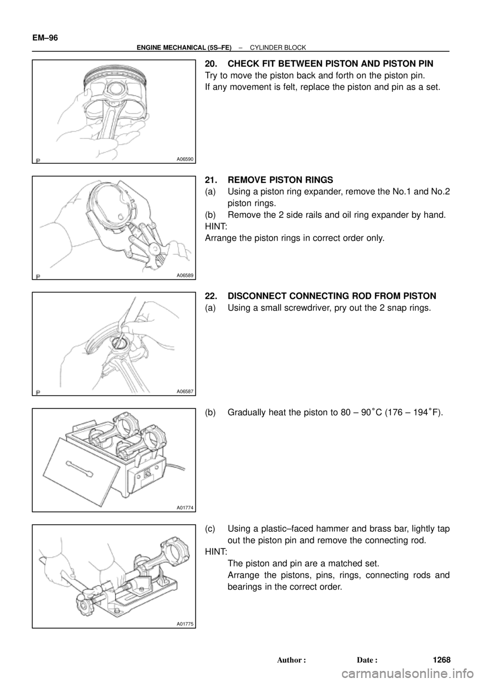
20. CHECK FIT BETWEEN PISTON AND PISTON PIN
Try to move the piston back and forth on the piston pin.
If any movement is felt, replace the piston and pin as a set.
21. REMOVE PISTON RINGS
(a) Using a piston ring expander, remove the No.1 and No.2
piston rings.
(b) Remove the 2 side rails and oil ring expander by hand.
HINT:
Arrange the piston rings in correct order only.
22. DISCONNECT CONNECTING ROD FROM PISTON
(a) Using a small screwdriver, pry out the 2 snap rings.
(b) Gradually heat the piston to 80 ± 90°C (176 ± 194°F).
(c) Using a plastic±faced hammer and brass bar, lightly tap
out the piston pin and remove the connecting rod.
HINT:
�The piston and pin are a matched set.
�Arrange the pistons, pins, rings, connecting rods and
bearings in the correct order.
Page 3501 of 4770
CYLINDER BLOCK
EM±109
1281 Author�: Date�:
(b) Align the bearing claw with the claw groove of the")
P03177
Mark
1, 2, 3, 4, or 5
P05354
P03173
S06012
P00104
1
10
735
84269
± ENGINE MECHANICAL (5S±FE)CYLINDER BLOCK
EM±109
1281 Author�: Date�:
(b) Align the bearing claw with the claw groove of the main
bearing cap, and push in the 5 lower bearings.
HINT:
A number is marked on each main bearing cap to indicate the
installation position.
5. INSTALL UPPER THRUST WASHERS
Install the 2 thrust washers under the No.3 journal position of
the cylinder block with the oil grooves facing outward.
6. PLACE CRANKSHAFT ON CYLINDER BLOCK
7. INSTALL MAIN BEARING CAPS AND LOWER
THRUST WASHERS
(a) Install the 2 thrust washers on the No.3 bearing cap with
the grooves facing outward.
(b) Install the 5 main bearing caps in their proper locations.
HINT:
Each bearing cap has a number and front mark.
(c) Apply a light coat of engine oil on the threads and under
the heads of the main bearing cap bolts.
(d) Install and uniformly tighten the 10 bolts of the main bear-
ing cap in several passes, in the sequence shown.
Torque: 59 N´m (600 kgf´cm, 43 ft´lbf)
(e) Check that the crankshaft turns smoothly.
8. CHECK CRANKSHAFT THRUST CLEARANCE
(See page EM±86)