Page 3516 of 4770
IGNITION TIMING
1296 Author�: Date�:
IGNITION TIMING
INSPECTION
1. WARM UP ENGINE
Allow")
EM04L±03
S05358
Hand±Held Tester TOYOTA
S04529
E1DLC1
SST
TE1
DLC1
A06644
EM±10
± ENGINE MECHANICAL (1MZ±FE)IGNITION TIMING
1296 Author�: Date�:
IGNITION TIMING
INSPECTION
1. WARM UP ENGINE
Allow the engine to warm up to normal operating temperature.
2. CONNECT TOYOTA HAND±HELD TESTER OR
OBDII SCAN TOOL
(a) Connect a TOYOTA hand±held tester or OBDII scan tool
to the DLC3.
(b) Please refer to the TOYOTA hand±held tester or OBDII
scan tool operator's manual for further details.
3. CONNECT TIMING LIGHT TO ENGINE
Connect the tester probe of a timing light to the No.1 high±ten-
sion cord for No.4 cylinder.
4. CHECK IDLE SPEED
(a) Race the engine speed at 2,500 rpm for approx. 90 se-
conds.
(b) Check the idle speed.
Idle speed: 700 ± 50 rpm
5. INSPECT IGNITION TIMING
(a) Using SST, connect terminals TE1 and E1 of the DLC1.
SST 09843±18020
(b) Using a timing light, check the ignition timing.
Ignition timing: 8 ± 12° BTDC @ idle
(Transmission in neutral position)
(c) Remove the SST from the DLC1.
SST 09843±18020
Page 3517 of 4770
± ENGINE MECHANICAL (1MZ±FE)IGNITION TIMING
EM±11
1297 Author�: Date�:
6. FURTHER CHECK IGNITION TIMING
Ignition timing: 7 ± 24° BTDC @ idle
(Transmission in neutral position)
HINT:
The timing mark moves in a range between 7° and 24°.
7. DISCONNECT TIMING LIGHT FROM ENGINE
8. DISCONNECT TOYOTA HAND±HELD TESTER OR
OBDII SCAN TOOL
Page 3552 of 4770
CYLINDER HEAD
1332 Author�: Date�:
(d) Check the valve overall length.
Standard over")
EM2534
Overall Length
EM0255
P12704
P12729
Width
Z03988
45°
1.0 ± 1.4 mm30° EM±46
± ENGINE MECHANICAL (1MZ±FE)CYLINDER HEAD
1332 Author�: Date�:
(d) Check the valve overall length.
Standard overall length:
Intake95.45 mm (3.5779 in.)
Exhaust95.40 mm (3.7559 in.)
Minimum overall length:
Intake94.95 mm (3.7382 in.)
Exhaust94.90 mm (3.7362 in.)
If the overall length is less than minimum, replace the valve.
(e) Check the surface of the valve stem tip for wear.
If the valve stem tip is worn, resurface the tip with a grinder or
replace the valve.
NOTICE:
Do not grind off more than minimum.
11. INSPECT AND CLEAN VALVE SEATS
(a) Using a 45° carbide cutter, resurface the valve seats.
Remove only enough metal to clean the seats.
(b) Check the valve seating position.
Apply a light coat of prussian blue (or white lead) to the
valve face. Lightly press the valve against the seat. Do not
rotate valve.
(c) Check the valve face and seat for the following:
�If blue appears 360° around the face, the valve is
concentric. If not, replace the valve.
�If blue appears 360° around the valve seat, the
guide and face are concentric. If not, resurface the
seat.
�Check that the seat contact is in the middle of the
valve face with the following width:
1.0 ± 1.4 mm (0.039 ± 0.055 in.)
If not, correct the valve seats as follows:
(1) If the seating is too high on the valve face, use 30°
and 45° cutters to correct the seat.
Page 3562 of 4770
Z19062
Intake ExhaustMark
TMC made
ºNOKº
TMMK made
ºFN , INº
Light Brown SurfaceGray Surface
P12668
(4)
(3)
(2)
(1)
P12476
SST
A05246
EM±56
± ENGINE MECHANICAL (1MZ±FE)CYLINDER HEAD
1342 Author�: Date�:
HINT:
The intake valve oil seal is light brown and the exhaust valve oil
seal is gray.
NOTICE:
Pay much attention when assembling the oil seal for intake
and exhaust. Assembling the wrong one may cause a fail-
ure.
(b) Install the valve (1), spring seat (2), valve spring (3) and
spring retainer (4).
(c) Using SST, compress the valve spring and place the 2
keepers around the valve stem.
SST 09202±70020 (09202±00010)
(d) Using a plastic±faced hammer and the valve stem (not in
use) tip wound with vinyl tape, lightly tap the valve stem
tip to assure proper fit.
NOTICE:
Be careful not do damage the valve stem tip.
4. INSTALL VALVE LIFTERS AND SHIMS
(a) Install the valve lifter and shim.
(b) Check that the valve lifter rotates smoothly by hand.
Page 3563 of 4770
CYLINDER HEAD
EM±57
1343 Author�: Date�:
INSTALLATION
1. PLACE C")
EM0YR±01
P12393
P12736
12 Pointed Head Bolt
Front7246
5318
7246 5318
P25742
Painted Mark
90°
Front90°
± ENGINE MECHANICAL (1MZ±FE)CYLINDER HEAD
EM±57
1343 Author�: Date�:
INSTALLATION
1. PLACE CYLINDER HEAD ON CYLINDER BLOCK
(a) Place 2 new cylinder head gaskets in position on the cylin-
der block.
NOTICE:
Be careful of the installation direction.
(b) Place the 2 cylinder heads in position on the cylinder head
gaskets.
2. INSTALL 12 POINTED HEAD CYLINDER HEAD BOLTS
HINT:
�The cylinder head bolts are tightened in 2 progressive
steps (steps (c) and (e)).
�If any bolt is broken or deformed, replace it.
(a) Apply a light coat of engine oil on the threads and under
the heads of the cylinder head bolts.
(b) Install the plate washer to the cylinder head bolt.
(c) Install and uniformly tighten the cylinder head bolts on
each cylinder head, in several passes, in the sequence
shown, then repeat for the other side, as shown.
Torque: 54 N´m (550 kgf´cm, 40 ft´lbf)
If any of the cylinder head bolts does not meet the torque speci-
fication, replace the cylinder head bolt.
(d) Mark the front of the cylinder head bolt head with paint.
(e) Retighten the cylinder head bolts by 90° in the numerical
order shown.
(f) Check that the painted mark is now at a 90° angle to the
front.
Page 3598 of 4770
P12404
P12405
P12403
P12416
60°C
P12415
EM±92
± ENGINE MECHANICAL (1MZ±FE)CYLINDER BLOCK
1378 Author�: Date�:
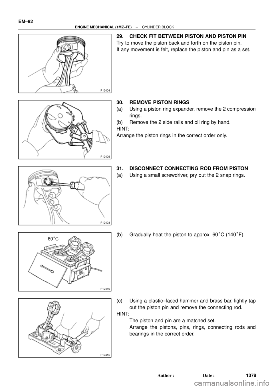
29. CHECK FIT BETWEEN PISTON AND PISTON PIN
Try to move the piston back and forth on the piston pin.
If any movement is felt, replace the piston and pin as a set.
30. REMOVE PISTON RINGS
(a) Using a piston ring expander, remove the 2 compression
rings.
(b) Remove the 2 side rails and oil ring by hand.
HINT:
Arrange the piston rings in the correct order only.
31. DISCONNECT CONNECTING ROD FROM PISTON
(a) Using a small screwdriver, pry out the 2 snap rings.
(b) Gradually heat the piston to approx. 60°C (140°F).
(c) Using a plastic±faced hammer and brass bar, lightly tap
out the piston pin and remove the connecting rod.
HINT:
�The piston and pin are a matched set.
�Arrange the pistons, pins, rings, connecting rods and
bearings in the correct order.
Page 3611 of 4770
CYLINDER BLOCK
EM±105
1391 Author�: Date�:
(a) Apply a light coat of eng")
P12753
10 11
12 13
14
151
162
3
45
6
7
89
P25741
Painted Mark
Front90°
90°
P12586
1
2
34
567
8
± ENGINE MECHANICAL (1MZ±FE)CYLINDER BLOCK
EM±105
1391 Author�: Date�:
(a) Apply a light coat of engine oil on the threads and under
the main bearing cap bolts.
(b) Install and uniformly tighten the 16 main bearing cap
bolts, in several passes, in the sequence shown.
Torque: 22 N´m (225 kgf´cm, 16 ft´lbf)
If any of the main bearing cap bolts does not meet the torque
specification, replace the main bearing cap bolt.
(c) Mark the front of the main bearing cap bolts with paint.
(d) Retighten the main bearing cap bolts by 90° in the numer-
ical order shown.
(e) Check that the painted mark is now at a 90° angle to the
front.
9. INSTALL HEXAGON HEAD MAIN BEARING CAP
BOLTS
(a) Install a new seal washer to the main bearing cap bolt.
(b) Install and uniformly tighten the 8 main bearing cap bolts,
in several passes, in the sequence shown.
Torque: 27 N´m (275 kgf´cm, 20 ft´lbf)
(c) Check that the crankshaft turns smoothly.
10. CHECK CRANKSHAFT THRUST CLEARANCE
(See page EM±83)
Page 3613 of 4770
CYLINDER BLOCK
EM±107
1393 Author�: Date�:
(a) Apply a light coat of engine oil on the threa")
P12697
P25743
Painted Mark
Front90°
90°
P12911
Seal Width
2 ± 3 mm A
BA
B
± ENGINE MECHANICAL (1MZ±FE)CYLINDER BLOCK
EM±107
1393 Author�: Date�:
(a) Apply a light coat of engine oil on the threads and under
the heads of the connecting rod cap bolts.
(b) Install and alternately tighten the 2 connecting rod cap
bolts in several passes.
Torque: 24.5 N´m (250 kgf´cm, 18 ft´lbf)
If any of the connecting rod cap bolts does not meet the torque
specification, replace the connecting rod cap bolts.
(c) Mark the front of the connecting cap bolts with paint.
(d) Retighten the cap bolts by 90° as shown.
(e) Check that the painted mark is now at a 90° angle to the
front.
(f) Check that the crankshaft turns smoothly.
14. CHECK CONNECTING ROD THRUST
CLEARANCE (See page EM±83)
15. INSTALL REAR OIL SEAL RETAINER
(a) Remove any old packing (FIPG) material and be careful
not to drop any oil on the contact surfaces of the oil seal
retainer and cylinder block.
�Using a razor blade and gasket scraper, remove all
the oil packing (FIPG) material from the gasket sur-
faces and sealing grooves.
�Thoroughly clean all components to remove all the
loose material.
�Using a non±residue solvent, clean both sealing
surfaces.
(b) Apply seal packing to the oil seal retainer as shown in the
illustration.
Seal packing: Part No. 08826±00080 or equivalent
�Install a nozzle that has been cut to a 2 ± 3 mm (0.08
± 0.12 in.) opening.
�Parts must be assembled within 3 minutes of ap-
plication. Otherwise the material must be removed
and reapplied.
�Immediately remove nozzle from the tube and rein-
stall cap.
(c) Install the oil seal retainer with the 6 bolts Uniformly tight-
en the bolt in several passes, in the sequence shown.
Torque: 8 N´m (80 kgf´cm, 69 in.´lbf)
16. INSTALL EGR COOLER
Install a new gasket and the EGR cooler with the 3 bolts and 2
nuts.
Torque: 9 N´m (90 kgf´cm, 78 in.´lbf)


(3)
(2)
(1)
P12476
SST
A05246
EM±56
± ENGINE MECHANICAL (1MZ±FE)CYLINDER HEAD
1342 Autho")