Page 4102 of 4770

FI2553
SST
S04600
Fuel
Pump
Connector
S05039
Plug
SF±2
± SFI (1MZ±FE)SFI SYSTEM
1501 Author�: Date�:
(b) When installing the battery, be especially careful not to in-
correctly connect the positive (+) and negative (±) cables.
(c) Do not permit parts to receive a severe impact during re-
moval or installation. Handle all SFI parts carefully, espe-
cially the ECM.
(d) Be careful during troubleshooting as there are numerous
transistor circuit, and even slight terminal contact can
cause further troubles.
(e) Do not open the ECM cover.
(f) When inspecting during rainy weather, take care to pre-
vent entry of water. Also, when washing the engine
compartment, prevent water from getting on the SFI parts
and wiring connectors.
(g) Parts should be replaced as an assembly.
(h) Care should be taken when pulling out and inserting wir-
ing connectors.
(1) Release the lock and pull out the connector, pulling
on the connectors.
(2) Fully insert the connector and check that it is locked.
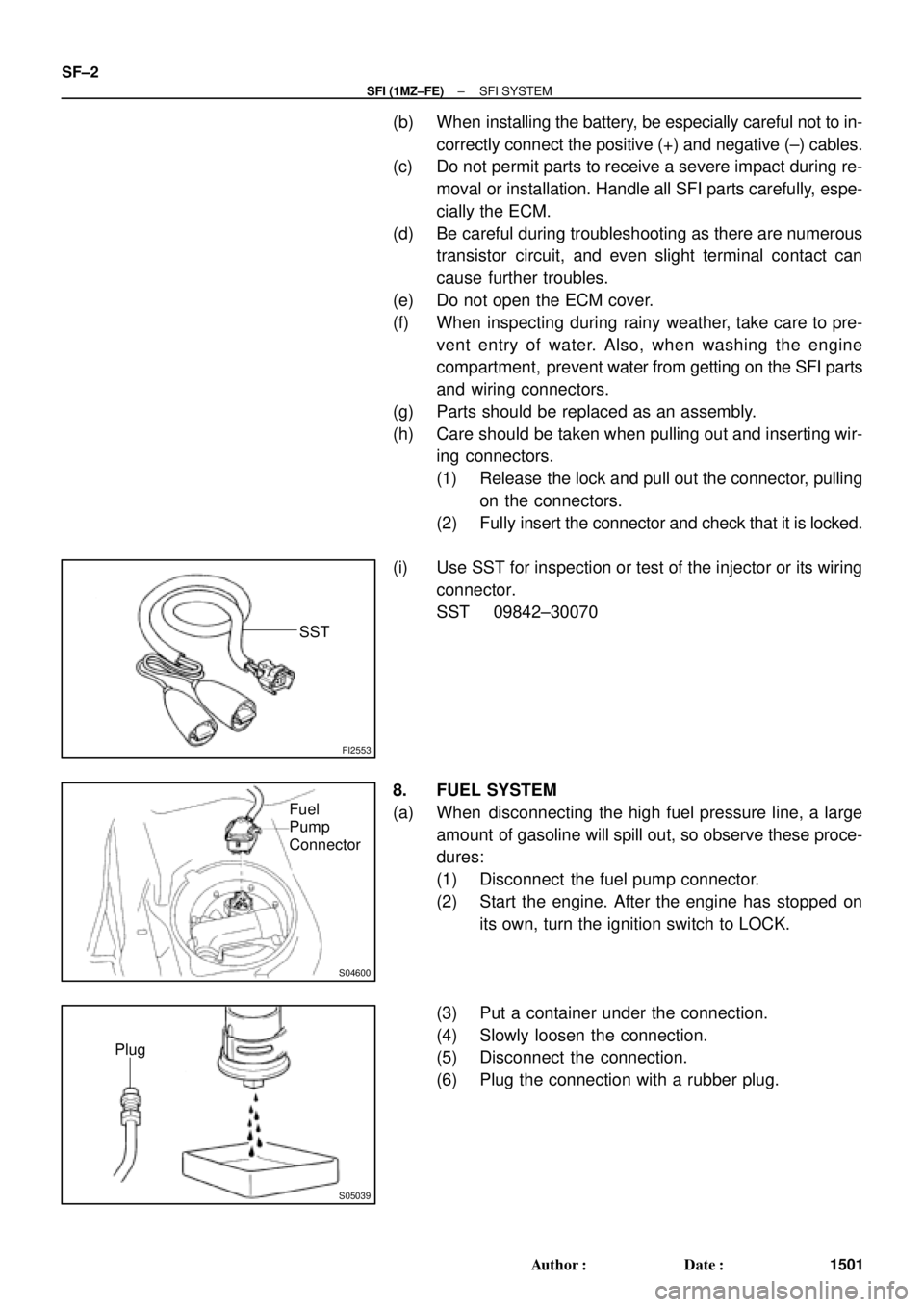
(i) Use SST for inspection or test of the injector or its wiring
connector.
SST 09842±30070
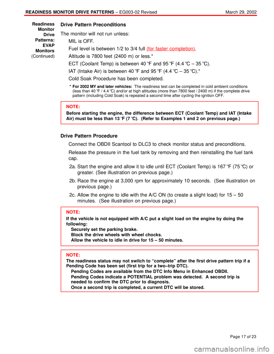
8. FUEL SYSTEM
(a) When disconnecting the high fuel pressure line, a large
amount of gasoline will spill out, so observe these proce-
dures:
(1) Disconnect the fuel pump connector.
(2) Start the engine. After the engine has stopped on
its own, turn the ignition switch to LOCK.
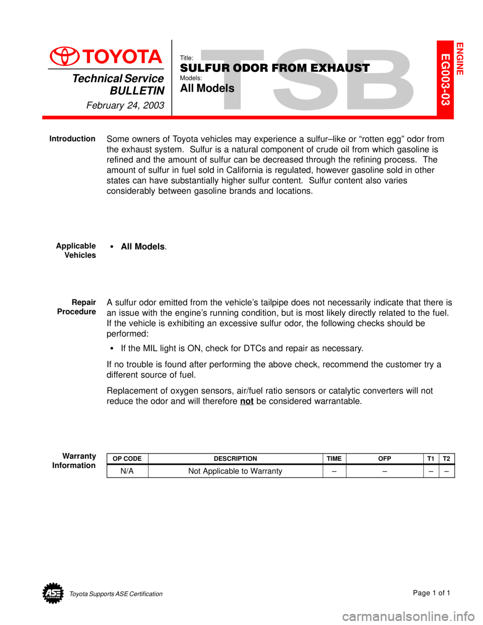
(3) Put a container under the connection.
(4) Slowly loosen the connection.
(5) Disconnect the connection.
(6) Plug the connection with a rubber plug.
Page 4298 of 4770
R07653
SR06G±01
F01477
SR±8
± STEERINGSTEERING WHEEL
2103 Author�: Date�:
STEERING WHEEL
INSPECTION
1. CHECK STEERING WHEEL FREEPLAY
With the vehicle stopped and tires facing straight ahead, rock
the steering wheel gently back and forth with light finger pres-
sure.
Freeplay should not exceed the maximum.
Maximum freeplay: 30 mm (1.18 in.)
2. CHECK STEERING EFFORT
(a) Center the steering wheel.
(b) Remove the steering wheel pad.
(See page SR±11)
(c) Start the engine and run it at idle.
(d) Measure the steering effort in both directions.
Reference: 5.9 N´m (60 kgf´cm, 52 in.´lbf)
HINT:
Be sure to consider the tire type, pressure and contact surface
before making your diagnosis.
(e) Torque the steering wheel set nut.
Torque: 35 N´m (360 kgf´cm, 26 ft´lbf)
(f) Install the steering wheel pad.
(See page SR±16)
Page 4548 of 4770

READINESS MONITOR DRIVE PATTERNS ± EG003-02 RevisedMarch 29, 2002
Page 17 of 23
Drive Pattern Preconditions
The monitor will not run unless:
�MIL is OFF.
�Fuel level is between 1/2 to 3/4 full (for faster completion)
.
�Altitude is 7800 feet (2400 m) or less.*
�ECT (Coolant Temp) is between 40�F and 95�F (4.4�C ± 35�C).
�IAT (Intake Air) is between 40�F and 95�F (4.4�C ± 35�C).*
�Cold Soak Procedure has been completed.
* For 2002 MY and later vehicles: The readiness test can be completed in cold ambient conditions
(less than 40�F / 4.4�C) and/or at high altitudes (more than 7800 feet / 2400 m) if the complete drive
pattern (including Cold Soak) is repeated a second time after cycling the ignition OFF.
NOTE:
Before starting the engine, the difference between ECT (Coolant Temp) and IAT (Intake
Air) must be less than 13�F (7�C). (Refer to Examples 1 and 2 on previous page.)
Drive Pattern Procedure
�Connect the OBDII Scantool to DLC3 to check monitor status and preconditions.
�Release the pressure in the fuel tank by removing and then reinstalling the fuel tank
cap.
2a. Start the engine and allow it to idle until ECT (Coolant Temp) is 167�F (75�C) or
greater. (See illustration on previous page.)
2b. Race the engine at 3,000 rpm for approximately 10 seconds. (See illustration on
previous page.)
2c. Allow the engine to idle with the A/C ON (to create a slight load) for 15 ± 50
minutes. (See illustration on previous page.)
NOTE:
If the vehicle is not equipped with A/C put a slight load on the engine by doing the
following:
�Securely set the parking brake.
�Block the drive wheels with wheel chocks.
�Allow the vehicle to idle in drive for 15 ± 50 minutes.
NOTE:
The readiness status may not switch to ªcompleteº after the first drive pattern trip if a
Pending Code has been set (first trip for a two±trip DTC).
�Pending Codes are available from the DTC Info Menu in Enhanced OBDII.
�Pending Codes indicate a POTENTIAL problem was detected. A second trip is
needed to confirm the DTC prior to diagnosis.
�Once a second trip is completed, a current DTC will be stored. Readiness
Monitor
Drive
Patterns:
EVAP
Monitors
(Continued)
Page 4555 of 4770

Toyota Supports ASE CertificationPage 1 of 1
EG003-03Title:
SULFUR ODOR FROM EXHAUST
Models:
All Models
Technical Service
BULLETIN
February 24, 2003
Some owners of Toyota vehicles may experience a sulfur±like or ªrotten eggº odor from
the exhaust system. Sulfur is a natural component of crude oil from which gasoline is
refined and the amount of sulfur can be decreased through the refining process. The
amount of sulfur in fuel sold in California is regulated, however gasoline sold in other
states can have substantially higher sulfur content. Sulfur content also varies
considerably between gasoline brands and locations.
�All Models.
A sulfur odor emitted from the vehicle's tailpipe does not necessarily indicate that there is
an issue with the engine's running condition, but is most likely directly related to the fuel.
If the vehicle is exhibiting an excessive sulfur odor, the following checks should be
performed:
�If the MIL light is ON, check for DTCs and repair as necessary.
If no trouble is found after performing the above check, recommend the customer try a
different source of fuel.
Replacement of oxygen sensors, air/fuel ratio sensors or catalytic converters will not
reduce the odor and will therefore not
be considered warrantable.
OP CODEDESCRIPTIONTIMEOFPT1T2
N/ANot Applicable to Warranty±±±±
ENGINE
Introduction
Applicable
Vehicles
Repair
Procedure
Warranty
Information