2000 TOYOTA CAMRY ECU
[x] Cancel search: ECUPage 1366 of 4770
15A
ECU±IG
1J 9
E 8 B 24 B 4A6
B 115A
STOP FROM POWER SOURCE SYSTEM (
SEE PAGE 50)
1C 7
A AAAAA B A
IG1R 5
1R 4 16 15 8 2
41
4 A
C
12332
AAA
C
W± BGNDST P± IDLO OD1 S2
7 13 14 6 9
ECT B
L±B L±B Y± B L±R
L±B
B± RL±B
B±R
W W±B
R±G
R±B
G±B R±Y W±B
G± W
W
W± BJUNCTION
CONNECTOR J25
JUNCTION
CONNECTOR J12
STOP LIGHT SW S 6
ENGINE CONTROL MODULEELECTRONICALLY
CONTROLLED
TRANSMISSION
SOLENOID
J UNCTION
CONNECTOR
CRUISE CONTROL ACTUATOR C 3
G±W G±W
* 1 : 1MZ± FE
* 2 : 5S±FE
J26(
*1)
(
*2)
CRUISE CONTROL ECU C15
(
A/T)
(
A/T)
(
A/ T) (
A/T) (
A/ T)
(
*1)
(
*2) (
*1)
1J 8
1J 7
W±B W± B
M
JUNCTION CONNECTOR J11
OD
IDL
MO MC L II2 7S2
A A
A A
JUNCTION
CONNECTOR B E 3 A , E 4
E E 9 C , E11
A 3A 3
A 20A 18
C 6(
*6) C 21(
*5)
B J 7 A , J 8
J27 A * 4 : EXCEPT * 3
* 5 : 5S±FE W/ ENGINE IMMOBILISER
* 6 : 5S±FE W/O ENGINE IMMOBILISER* 3 : TMMK MADE 1MZ±FE E 7 BA, E 8 ,
,
Page 1367 of 4770

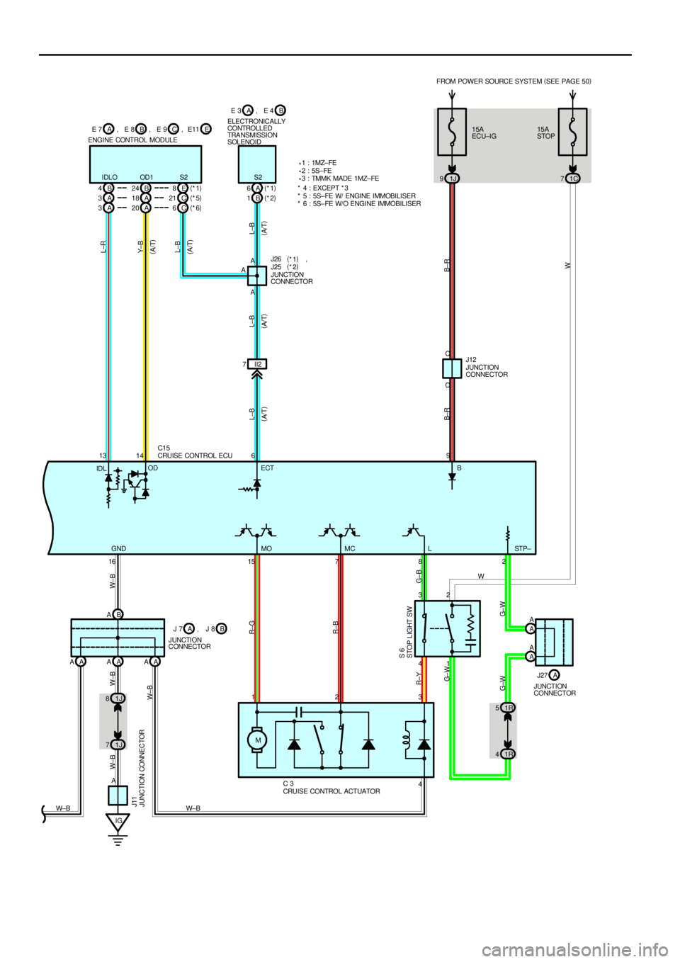
CRUISE CONTROL
Current is applied at all times through the STOP fuse to TERMINAL 2 of the stop light SW.
With the ignition SW turned to on, current flows through the GAUGE fuse to TERMINAL (C) 7 of the combination meter and
the current through the ECU±IG fuse flows to TERMINAL 9 of the cruise control ECU.
When the ignition SW is on and the cruise control SW is turned on, a signal is input from TERMINAL 5 of the cruise control
SW to TERMINAL 11 of the cruise control ECU. As a result, the cruise control ECU functions and the current flows from the
ECU±IG fuse to TERMINAL 9 of the cruise control ECU to TERMINAL 16 to GROUND, and the cruise control system is in a
condition ready for operation.
At the same time, the current through the GAUGE fuse flows to TERMINAL (C) 7 of the cruise control indicator light to
TERMINAL (C) 10 to TERMINAL 4 of the cruise control ECU to TERMINAL 16 to GROUND, causing the cruise control
indicator light to light up, indicating that cruise control is ready for operation.
1. SET OPERATION
When the cruise control SW is turned on and the set SW is pushed with the vehicle speed within the set limit (Approx. 40
km/h, 25 mph to 200 km/h, 124 mph), a signal is input to TERMINAL 10 of the cruise control ECU and the vehicle speed at
the time the set SW is released is memorized in the ECU as the set speed.
2. SET SPEED CONTROL
During cruise control driving, the cruise control ECU compares the set speed memorized in the cruise control ECU with the
actual vehicle speed input into TERMINAL 12 of the cruise control ECU from the speed sensor, and controls the cruise
control actuator to maintain the set speed.
When the actual speed is lower than the set speed, the ECU causes the current to the cruise control actuator to flow from
TERMINAL 15 of the cruise control ECU to TERMINAL 1 of the cruise control actuator to TERMINAL 2 to TERMINAL 7 of
the cruise control ECU. As a result, the motor in the cruise control actuator is rotated to open the than the set speed, the
current to the cruise control actuator flows from TERMINAL 7 of the cruise control ECU to TERMINAL 2 of the cruise control
actuator to TERMINAL 1 to TERMINAL 15 of the cruise control ECU.
This causes the motor in the cruise control actuator to rotate to close the throttle valve and return the throttle cable to
decrease the vehicle speed.
3. COAST CONTROL
During cruise control driving, while the coast SW is on, the cruise control actuator returns the throttle cable to close the
throttle valve and decrease the driving speed. The vehicle speed when the coast SW is turned off is memorized and the
vehicle continues at the new set speed.
4. ACCEL CONTROL
During cruise control driving, while the accel SW is turned on, the cruise control actuator pulls the throttle cable to open the
throttle valve and increase the driving speed.
The vehicle speed when the accel SW is turned off is memorized and the vehicle continues at the new set speed.
5. RESUME CONTROL
Unless the vehicle speed falls below the minimum speed limit (Approx. 40km/h, 25mph) after canceling the set speed by the
cancel SW, pushing the resume SW will cause the vehicle to resume the speed set before cancellation.
6. MANUAL CANCEL MECHANISM
If any of the following operations occurs during cruise control operation, the magnetic clutch of the actuator turns off and the
motor rotates to close the throttle valve and the cruise control is released.
*Placing the shift lever except D position (Park/Neutral position SW except D position). ºSignal is not input to TERMINAL 3
of the cruise control ECUº (A/T)
*Depressing the clutch pedal (Cruise control clutch SW off). ºSignal input to TERMINAL 3 of the cruise control ECUº (M/T)
*Depressing the brake pedal (Stop light SW on). ºSignal input to TERMINAL 2 of the cruise control ECUº
*Pushing the cancel switch (Cancel SW on). ºSignal input to TERMINAL 10 of the cruise control ECUº
*Pushing the cruise switch off ºsignal input to TERMINAL 11 of the cruise control ECUº.
SYSTEM OUTLINE
Page 1368 of 4770

7. TAP±UP CONTROL FUNCTION
When the difference between the actual vehicle speed and the set speed is less than 5 km/h (3 mph), the set speed can be
increased 1.6 km/h (1 mph) each time by operation the RESUME/ACCEL SW quickly within 0.6 seconds.
8. TAP±DOWN CONTROL FUNCTION
When the difference between the actual vehicle speed and the set speed is less than 5 km/h (3 mph), the set speed can be
lowered 1.6 km/h (1 mph) each time by operating the SET/COAST SW quickly within 0.6 seconds.
9. AUTO CANCEL FUNCTION
A) If any of the following operating conditions occurs during cruise control operation, the set speed is erased, the current
flow to the magnetic clutch is stopped and the cruise control is released. (Cruise SW turns off).
When this occurs, the ignition SW must be turned off once before the cruise SW will turn on.
*When current continued to flow to the motor inside the actuator in the throttle valve ºOPENº direction.
*The motor does not operate despite the motor drive signal being output.
B) If any of the following operating conditions occurs during cruise control operation, the set speed is erased, the current
flow to the magnetic clutch is stopped and the cruise control is released. (Cruise SW turn off).
When this occurs, the cancel state is cleared as the cruise SW will turn on again.
*Over current to transistor driving the motor and/or the magnetic clutch.
*Open circuit in the magnetic clutch.
*Momentary interruption of vehicle speed signal.
*Short circuit in the cruise control SW.
*When the vehicle speed falls more than 16 km/h (10 mph) below the set speed, E.G. on an upward slope.
C) If any of the following conditions occurs during cruise control operation, the set speed is erased and the cruise control is
released. (The power to the magnetic clutch is cut off until the set SW is ON again.)
*When the vehicle speed falls below the minimum speed limit, approx. 40 km/h (25 mph).
*When power to the cruise control system is momentarily cut off.
D) If any of the following conditions occurs during cruise control operation, the cruise control is released.
*Open the circuit for TERMINAL 2 of the stop light SW.
10. AUTOMATIC TRANSAXLE CONTROL FUNCTION
*In overdrive. If the vehicle speed becomes lower than the overdrive cut speed (Set speed minus approx. 4 km/h, 2.5 mph)
during cruise control operation, such as driving up a hill, the overdrive is released and the power increased to prevent a
reduction in vehicle speed.
*After releasing the overdrive, vehicle speed becomes higher than the overdrive return speed (Set speed minus approx. 2
km/h, 1.2 mph) and the cruise control ECU judges by the signals from the actuator's potentiometer that the upward slope
has finished, the overdrive is resumed after approximately 2 seconds.
*During cruise control driving, the cruise control operation signal is output from the cruise control ECU to the engine control
module. Upon receiving this signal, the engine control module changes the shift pattern to normal.
To maintain smooth cruise control operation (on a downward slope etc.), the lock±up release of the transmission when the
idling point of the throttle position is ON is forbidden.
C3 CRUISE CONTROL ACTUATOR
3±4 : Approx. 38.5 W
C12 CRUISE CONTROL SW [COMB. SW]
5±3 : Continuity with the CRUISE SW on
4±3 : Approx. 418 W with the CANCEL SW on
Approx. 68 W with the RESUME/ACCEL SW on
Approx. 198 W with the SET/COAST SW on
C15 CRUISE CONTROL ECU
9±GROUND :10±14 volts with the ignition SW at ON position
12±GROUND :4 pulses with 1 rotation of rotor shaft
10±GROUND : Approx. 418 W with the CANCEL SW on in the cruise control SW
Approx. 198 W with the SET/COAST SW on in the cruise control SW
Approx. 68 W with the RESUME/ACCEL SW on in the cruise control SW
16±GROUND : Always continuity
SERVICE HINTS
Page 1373 of 4770
ABS AND TRACTION CONTROL
60A
FL ABS
2 1 FROM POWER SOURCE SYSTEM (
SEE PAGE 50)
36 2143
3
33 3 33 3
A 1A24
A 11
A 3 A 9A 13 A26
B4
EA E 1E 1 E 1C 9C10 SR GND3 GND2 SFRH SFRRR+ MR
SFRR SFRH
BS 23
14
W±RR±B W±B W±B W±RGR ±R
W±R GR W± L W± B W±B W±B
R±L
W± R
W±B W±B GR
GR±R
GR±L
GR± L
GR± R
R±L
ABS AND TRACTION ECU
ABS AND TRACTION
ACTUATOR W± L ABS
MOTOR
RELAY
ABS
SOL
RELAY
W±B 5
B A 7 A , A 8 B A15 A , A16 C, A17
Page 1374 of 4770
C 2C1C8C7A25 A12 C5C4C12 C6A10 A14
A 12 A6A11 A5A10 A4A7A2A8A1B5B3
M
B 2B1
E 1 SFLH SFLR SRRH SRRR SRLH SRLR SRC1 SRC2 SMC1 SMC2 AST MT
AST MT SMC2 SMC1 SRC2 SR C1 SRLR SRLH SRRR SRRH SFLR SFLH
GN D BM
L±B
W±L
W±R
R±G
G± Y
LG±B
B±R
B±Y
Y±R
Y±B
R
R±W
W± RW± RW±B
15A
E CU±IG FROM POWER SOURCE SYSTEM (
SEE PAGE 50)
1J 9
B 815A
STOP
1C 7
1 2
1R 41R 5A A
B C
B 16 JUNCTION
CONNECTOR J12
STOP
LIGHT SW S 6
JUNCTION
CONNECTOR
ABS AND TRACTION ECU C C
B±R
W
G± WB±R
G± WG±W
R±L R±L
W± BW±B IG1STP
ABS AND TRACTION ACTUATORA 15GND1
W± B
A15 BA, A16 C, A17
B A 7 A , A 8B J27 A , J28
Page 1375 of 4770
ABS AND TRACTION CONTROL
II3 4II38II35II311
IK2 8IK25
A 23 B4A9IK2 12 IK12
A 22 B12 CB CB
B
C 23 16 22 11 4 14 17
TS WA TC D/G WT TS TC TC ABS TRC
L G±BR±YR±L R±L
R±Y
G±B
LG±R LG±R LG±RR±Y
G±B
R±L
LR±L LG±R
L
R±L DATA LINK CONNECTOR 1 D 1
DATA LINK CONNECTOR 2 D 4
JUNCTION
CONNECTOR J 3 JUNCTION
CONNECTOR J29
ABS AND TRACTION ECU R±L(
SHORT PIN)
WB WA
G±B LG±R
R±L
A 5A4A17 A18 B2B1
1 21221 ID1 3ID19ID14
ABS SPEED SENSOR
FRONT L H A 9
ABS SPEED SENSOR
FRONT RH A10
ABS SPEED SENSOR
REAR LH A25B 9B10
2 1 IL1 2IL11IL13
ABS SPEED SENSOR
REAR RH A2 6 FL+ FL± FR+ FR± RL+ RL± RR+ RR±
B W W±BR
G
W
B
R
G R
G
Y
BR(
*2)
P
L(
*2) (
SHIELDED) (
SHIELDED)
W± B
IG312
R±LE1
BR 3
C C
C
JUNCTION
CONNECTOR J32
A A15 BA16 , C, A17
BRY± B
(
*2)
P± B
(
*2) (
*1)
LG±R
(
*1)
IK2 1IK26
R
(
*1)
G
(
*1) (
*2)
(
*2)
(
*2) W
(
*1)
(
*1) B
(
*2)
W±B
(
*2)
(
*2) (
*2)
Page 1376 of 4770
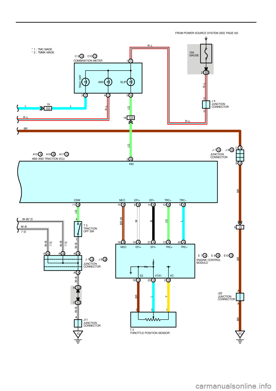
IG 1J 71J 8B 5 B 13 B 14 B 6 B 15
B 16 A14 A21 A13 A20
D 18 D23 D2 B 11
1 4
AA AB A B A B ATRC± TRC+ EFI± EFI+ NE O CSW
BR±W
W
B
LG
L YL BRLG W±B W±B W±BW±B
W±BW± BW± B(
*2)
JUNCTION
CONNECTOR J11
THROTTLE POSITION SENSOR T 2 TRACTI ON
OFF SW T 5 ABS AND TRACTION ECU
JUNCTION
CONNECTOR
E2 VTA1 VC NEO EFI+ EFI± TRC+ TRC±
23110A
GAU GE FROM POWER SOURCE SYSTEM (
SEE PAGE 50)
1D 2
B 3IG3 18A 5 C 4 C 3
IG319C 7
L
R±LLR±L
R±L
LG R±L
LG
R±L
JUNCTION
CONNECTOR J 4 COMBINATION METER
INDD D
TRA C OFF
ABS SLIP
ECII3 6A C
B B
A A BR
BR BR BR
B A15 A , A16 CA17 , C C 8 A , C10
B J 7 A , J 8J 7
JUNCTION
CONNECTORB A, J 8
JUNCTION
CONNECTOR J22 ENGINE CONTROL
MODULEA E 7 BE 8 , D, E10 (
*2)
(
*2)
(
*2)
* 1 : TMC MADE
* 2 : TMMK MADE
Page 1377 of 4770
ABS AND TRACTION CONTROL
(ABS)
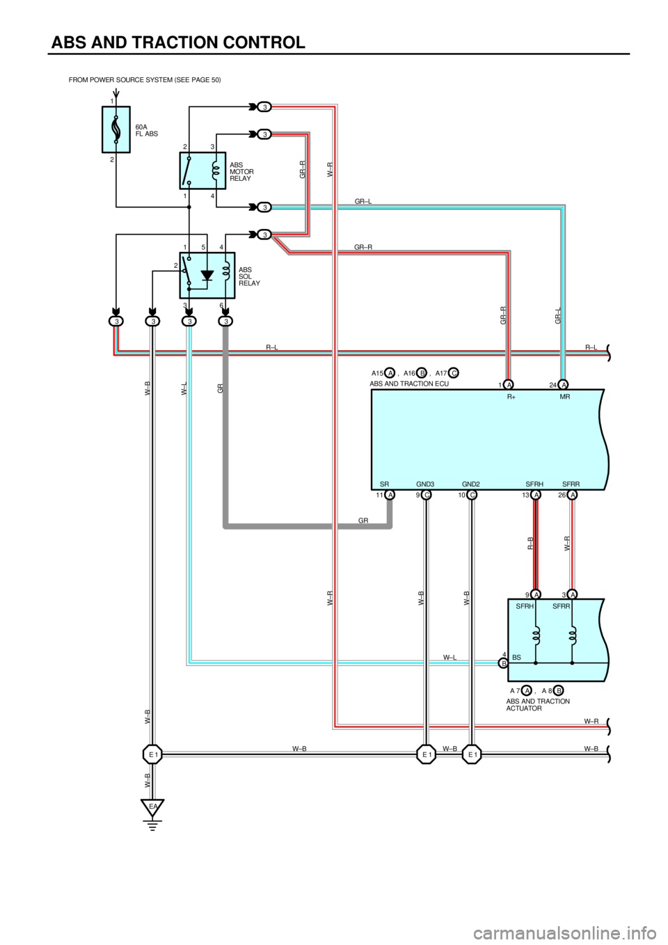
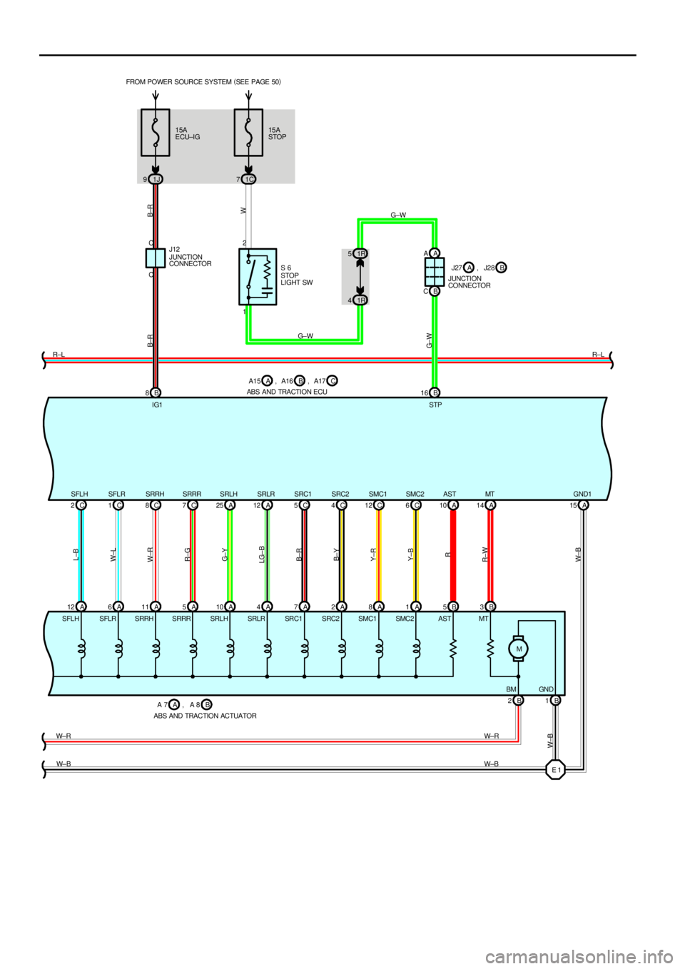
ABS is a brake system designed for the purpose to improve the operating ability securing the stability of the vehicle by
preventing the looking±up of the vehicle controlling the wheel cylinder pressure of all the four wheels at the time of sudden
braking.
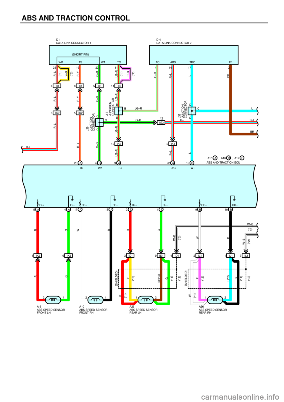
1. INPUT SIGNALS
(1) Speed sensor signal
The speed of the wheels is detected and input to TERMINALS FL+, FR+, RL+, and RR+ of the ABS and traction ECU.
(2) Stop light SW signal
A signal is input to TERMINAL STP of the ABS and traction ECU when brake pedal is depressed.
2. SYSTEM OPERATION
When the wheels are to be locked±up, the solenoid inside the actuator will be controlled by the signal from the ABS and
traction ECU and the brake fluid in the wheel cylinder will flow through the reservoir and reduce the hydraulic pressure.
While the ABS is in operation, as the ABS and traction ECU always outputs the operation signal to the pump inside the
actuator, brake fluid stored inside the reservoir will be suctioned up by the pump inside the actuator and returned to the
master cylinder.
When the hydraulic pressure of the wheel cylinder is decompressed or increased until the necessary hydraulic pressure, the
solenoid inside the actuator is controlled by the control signal from the ABS and traction ECU and as a result, hydraulic
pressure of the wheel cylinder will be closed at both routes of the master cylinder and reservoir sides and the hydraulic
pressure of the wheel cylinder will become to be in the holding condition.
If the increase of hydraulic pressure volume of the wheel cylinder becomes necessary, with the control signal from the ABS
and traction ECU, the solenoid inside the actuator will be controlled and become the same condition as usual and the brake
fluid of the master cylinder will be sent to the wheel cylinder and will increase the hydraulic pressure of the wheel cylinder. At
this time, in the case that the brake fluid stays left in the reservoir, it will be sucked up by the pump inside the actuator and
will be sent to the wheel cylinder.
Also, increasing speed of the hydraulic pressure is controlled by outputting the increasing and the said holding one after
another.
(Traction control)
Traction control system is designed to perform the engine output control by the fuel cut and hydraulic pressure control of
driving wheel brake and control the spinning of the driving wheels. By doing this, it improves starting acceleration and
operating ability of the vehicle securing the driving ability in accordance with the road surface condition.
3. TRACTION CONTROL OPERATION
Estimating the vehicle speed from the rear wheel speed, comparing it with the front, driving wheel speed and judging the grip
condition of the driving wheels. From the estimated vehicle speed, target speed of the driving speed will be set. When the
front, driving wheel speed exceeds the control starting speed, it judges that the tire slip is occurred and performs the fuel cut
cylinder number control and brake control and then adjust to make the front wheel speed become the traction control target
speed. Controlling of the traction control will be completed when the vehicle move onto the road where the driving wheels will
not have a tire slip or when the driver decelerate.
ABS MOTOR RELAY [R/B NO.3]
3±4 : Approx. 62 W
ABS SOL RELAY [R/B NO.3]
4±6 : Approx. 80 W
A9, A10 ABS SPEED SENSOR FRONT LH, RH
1±2 :0.6 kW±2.5 kW
A15 (A), A16 (B), A17 (C) ABS AND TRACTION ECU
(B) 8±GROUND : Approx. 12 volts with the ignition SW at ON position
(B)11±GROUND : Continuity with the ignition SW on and the traction off SW on (Traction control off)
(B)16±GROUND : Approx. 12 volts with the brake pedal depressed
(A)15, (C) 9, (C) 10±GROUND : Always continuity
A25, A26
ABS SPEED SENSOR REAR LH, RH
1±2 :1.2 kW±2.3 kW
T2 THROTTLE POSITION SENSOR
1±2 :3.5 kW±5.0 kW
SYSTEM OUTLINE
SERVICE HINTS