2000 TOYOTA CAMRY ECU
[x] Cancel search: ECUPage 1214 of 4770
2K 7
2F 42C10 23 15
E 4E3E2E1DD5 B BBB A BAB
A 16 A1
EB15A
EFI FROM POWER SOURCE SYSTEM (
SEE PAGE 50)
II3 9
B±Y B±Y B±Y
B±Y B±W
B±R
G
R±L
W
Y
R
LB±Y
B±YB±YB±R W± B
R±L
W
Y
R
L W± B
EFI RELAY
B±Y
+B BATT
ENGINE CONTROL MODULEB E 7 E 8ACE 9 FC
#60 #50 #40 #30 #20 #10 2C 5
W± B
B 16NEO
BR±W
A 14EFI+
W
A 21EFI±
B
A 13TRC+
LG
A 20TRC±
L
FROM ABS AND
TRACTI ON ECU 2J8
A EAE
B±Y
, , ,
A2
B±R
W± B B±W B±W
2
2J
B±W
B±Y B±Y
B(
*1)
B(
*1)
B±Y
B± Y
D E10 EE11 , 3
A G±R
G IGSWMRELA BB C
A 7P
N5 B±W B
JUNCTION
CONNECTORB J 7 J 8A
PARK/NEUTRAL
POSITION SW
JUNCTION
CONNECTOR
P 1
J29
STAB 20 B
B± W
, B
II2 11
10
II2 2 1
GR(
*4 A/T)B±W
B±W
B±O
GR
* 1 : CALIFORNIA
* 4 : TMC MADE
* 3 : W/ ENGINE IMMOBILISER SYSTEM6
B± O
GR
B±W(
A/T)(
M/T)
(
*5)
(
*4)
(
*5 A/T)C 7
CLUTCH START
SW
(
A/T)
A 8B±W
* 2 : W/ TRACTION CONTROLC 10TXCT
L±Y
C 5RXCK
R±L
C 4CODE
G±W
TO TRANSPONDER
KEY AMPLIFIER
(
*3)
(
*3)
(
*3)
6
(
*1)
(
*2)
(
*2)
(
*2)
(
*2)
(
*2)(
A/T)
B C
B±O(
*5 M/T) GR(
*4 M/T)
B B
NSW A 9ID1 1
VV
ID1 10
B±Y
2 1VSV (
VAPOR
PRESSURE SENSOR) V 7
B± Y
J27
JUNCTION
CONNECTORB A, J28
TPC
* 5 : TMMK MADE
Page 1216 of 4770
I 2
I 2 I 2
I 2 I 21 2
1 2D 3
D 18 D23 D2D13 D14 A17 E 22D 9
1 II1 2
13 213 1 3 1
3 1 A
2312 34 2 4 2 2 B±Y
BR(
*1) BR
BR Y BR E2 VTA1 VC THG THW PTNKEGLSPS RSO RSC HTS OXS HAFR
B±LW± G
P BR
YY
BR BR
G±B G±Y YL BR BR
Y
R±W
Y±B
P±B
B
B± R(
*1)
BR(
*1)BBR BRB±Y B±Y
B±Y
(
SHIELDED)
(
SHIELDED)(
SHIELDED) Y
A
IDLE AIR CONTROL VALVE
HEATED OXYGEN SENSOR
(
BANK 1 SENSOR 2)
AIR FUEL RATIO SENSOR
(
BANK 1 SENSOR 1) I 1
H 8
A28
JUNCTION
CONNECTOR J20
T 2
THROTTLE POSITION SENSOR
EGR GAS TEMP. SENSOR
ENGINE COOLANT TEMP. SENSOR
VAPOR PRESSURE SENSOREGR VAL VE
POSITION SENSOR
POWER STEERING
OIL PRESSURE SWE 1
E 5
V 1E 2
P 2
ENGINE CONTROL MODULEB E 7 E 8ACE 9 DE10+B E1
HT OX
PTNK
E2 VCC
E2 VTA VC BRI 2ID1 6IG34II2 1 C 16
6
IND
P
R±Y R±Y R±Y
G± W G±W
E 29
FROM FAN NO. 1 RELAYCF
IMLD , , , EE1 1 , B B
B JUNCTION
CONNECTOR J2 4
B(
*1)
THEFT
DETERRENT
ECU T 3 BR B(
*1)
AFR± AFR+
B D
B D
B J10
JUNCTION
CONNECTOR E 16 E15 B9B8D11 D20
G(
*1 *4)
BR(
*1 *5)
R(
*1 *4)
B±R(
*1 *5)
B(
*1) B±Y
D 12 D4 I 2 BR
I 2
I 2 42
31A
OX HTBR
B
Y±RBR
B±Y (
SHIELDED)
(
*6)(
*6)
(
*6)
(
*6) (
*6) (
*6)
OXL1 HTLE1 +B
HEATED OXYGEN SENSOR
(
BANK 2 SENSOR 1) H 4
(
SHIELDED)BR(
*6)
BR(
*6)BR(
*6) BR(
*6)
II13
ID15 II1 4ID12
BRBR
YBR(
*6)
* 1 : CALIFORNIA
* 4 : TMC MADE
* 5 : TMMK MADE
* 6 : EXCEPT CALIFORNIA
(
*1)
Page 1232 of 4770
FROM POWER SOURCE SYSTEM (
SEE PAGE 50)
1C 91J11
1 2
2 1
IK2 7IK22
IK2 9II3 10 II21
1 I 2 I 2
A 10 A 20 A21 A19 C19 B11 C4 B 6C8B15 C4C17 C5A2
2 1 B8 1 3
2 A
B4 2123
A
1 3
2 5 1
BR
B±YBR BRB±Y(
*6) B±Y
BR
BR
BR
BR
BR
B±Y PS SW THR LOCK IN PRS MGC TE1
A/C SW LOCK
B±LL±R L±W BRW±L W±L W±LG L±Y
G L±YR±BR±B R±W
R±BW
L±Y
L±W
B±R
BR
L
B±W
G±O G±O
B±YB±Y
BR
B±Y
BR
OX1 HT1 TE1 NE+ NE± G+ E LSE1 +B
10A TAIL
10A
MIRROR±
HEATER (
SHIELDED)
(
SHIELDED) (
SHIELDED)
(
*6) (
*6)(
*6)
(
*6)
L
B±R
(
*6)
DIODE
(
IDLE±UP)
HEATED OXYGEN SENSOR
(
BANK 1 SENSOR 1)
DATA LINK
CONNECTOR 1
CRANKSHAFT
POSITION SENSOR
CAMSHAFT
POSITION SENSOR
JUNCTION
CONNECTORH 3
D 1
C 2
C 1
J12
D11
JUNCTION CONNECTOR
A/C SWHEATER CONTROL SW
A/C EVAPORATOR
TEMP. SENSOR
POWER STEERING OIL PRESSURE SWFROM MG
CLT RELAY
FROM
A/C DUAL
PRESSURE SW
FROM A/ C
MAGNETIC
CLUTCH AND
LOCK SENSORJ12
A13
P 2H 9
A14* 5 : CALIFORNIA
* 6 : EXCEPT CALIFORNIA
BR
ENGINE CONTROL MODULEB E 7 E 8ACE 9 +B E1
OX HT* 1 : W/ ENGINE IMMOBILISER SYSTEM
* 2 : W/O ENGINE IMMOBILISER SYSTEM
, , DE10 , B 5C1B7D12 D6D11 A13(
*1)
(
*2)
IG3 8D 4KSW
L±B L±B L±B
TO UNLOCK
WARN ING SW
A 10 A 15 A21 A13 C18 B10 B12
IG3 4II4 3D 1IMLD
R±Y R±Y R±Y
6
IND R±YTHEFT DETERRENT
ECU T 3
(
*1)
(
*2) D 3D8D9TXCT CODE RXCK
R±L
G± W
L±Y
TO TRANSPONDER
KEY AMPLIFIER
DD
J10
JUNCTION
CONNECTORII4 9 * 3 : TMC MADE
* 4 : TMMK MADE
Page 1299 of 4770

DOOR LOCK CONTROL (TMC MADE)
Current always flows to TERMINAL (A) 13 (w/o theft deterrent system), (B) 1 (w/ theft deterrent system) of the integration
relay through the DOOR fuse.
When the ignition SW is turned on, the current flowing through the GAUGE Fuse flows to TERMINAL 7 of the integration
relay to TERMINAL (A) 12 (w/o theft deterrent system), (B) 3 (w/ theft deterrent system) to the power relay (Coil side) to
GROUND.
1. MANUAL LOCK OPERATION
When the door lock control SW or door key lock and unlock SW are operated to LOCK position, a lock signal is input to
TERMINAL (A) 1 or (A) 3 (w/o theft deterrent system), (B) 16 or (B) 18 (w/ theft deterrent system) of the integration relay and
causes the relay to function. Current flows from TERMINAL (A) 13 (w/o theft deterrent system), (B) 1 (w/ theft deterrent
system) of the relay to (A) 6 (w/o theft deterrent system), (B) 12 (w/ theft deterrent system) to TERMINAL 2 of the door lock
motors to TERMINAL 3 to TERMINAL (A) 7 (w/o theft deterrent system), (B) 11 and (B) 25 (w/ theft deterrent system) of the
relay to TERMINAL 10 to GROUND and the door lock motor causes the door to lock.
2. MANUAL UNLOCK OPERATION
When the door lock control SW or door key lock and unlock SW are operated to UNLOCK position, an unlock signal is input
to TERMINAL (A) 2, (A) 4 or (A) 5 (w/o theft deterrent system), (B) 17, (B) 19 or (B) 20 (w/ theft deterrent system) of the
integration relay and causes the relay to function. Current flows from TERMINAL (A) 13 (w/o theft deterrent system), (B) 1 (w/
theft deterrent system) of the relay to TERMINAL (A) 7 (w/o theft deterrent system), (B) 11 and (B) 25 (w/ theft deterrent
system) to TERMINAL 3 of the door lock motors to TERMINAL 2 to TERMINAL (A) 6 (w/o theft Deterrent system), (B) 12 (w/
theft deterrent system) of the relay to TERMINAL 10 to GROUND and door lock motors causes door to unlock.
3. DOUBLE OPERATION UNLOCK OPERATION
When the door key lock and unlock SW front LH is turned to the unlock side, only the driver's door is mechanically unlocked.
Turning the door key lock and unlock SW front LH to the unlock side causes a signal to be input to TERMINAL (A) 4 (w/o
theft deterrent system), (B) 19 (w/ theft deterrent system) of the relay, and if the signal is input again within 3 seconds by
turning the SW to the unlock side again, current flows from TERMINAL (A) 7 (w/o theft deterrent system), (B) 11 and (B) 25
(w/ theft deterrent system) of the integration relay to TERMINAL 3 of the door lock motors to TERMINAL 2 of the door lock
motors to TERMINAL (A) 6 (w/o theft deterrent system), (B) 12 (w/ theft deterrent system) of the relay to TERMINAL 10 to
GROUND, causing the door lock motors to operate and unlock the doors.
4. IGNITION KEY REMINDER OPERATION
*Operating door lock knob (Operation of door lock motors)
With ignition key in cylinder (Unlock warning SW on), when the door is opened and locked using door lock knob (Door
lock motor), the door is locked once but each door is unlocked soon by the function of the relay. As a result, the current
flows from TERMINAL (A) 13 (w/o theft deterrent system), (B) 1 (w/ theft deterrent system) of the integration relay to
TERMINAL (A) 7 (w/o theft deterrent system),(B) 11 and (B) 25 (w/ theft deterrent system) to TERMINAL 3 of the door
lock motors to TERMINAL 2 of the door lock motors to TERMINAL (A) 6 (w/o theft deterrent system), (B) 12 (w/ theft
deterrent system) of the relay to TERMINAL 10 to GROUND and causes all the doors to unlock.
*Operating door lock control SW or door key lock and unlock SW
With ignition key in cylinder (Unlock warning SW on), when the door is opened and locked using door lock control SW or
key SW, the door is locked once but each door is unlock by the function of SW contained in motors, which the signal is
input to TERMINAL (A) 9 or (A) 10 (w/o theft deterrent system), (B) 5 or (B) 7 (w/ theft deterrent system) of the relay.
According to this input signal, the current in ECU flows from TERMINAL (A) 13 (w/o theft deterrent system), (B) 1 (w/
theft deterrent system) of the relay to TERMINAL (A) 7 (w/o theft deterrent system), (B) 11 and (B) 25 (w/ theft deterrent
system) to TERMINAL 3 of the door lock motors to TERMINAL 2 of the door lock motors to TERMINAL (A) 6 (w/o theft
deterrent system), (B) 12 (w/ theft deterrent system) of the relay to TERMINAL 10 to GROUND and causes all the doors
to unlock.
*In case of key less lock
With ignition key in cylinder (Unlock warning SW on), when the unlock function is disturbed more than 0.2 seconds, for
example pushing the door lock knob etc., the door holds on lock condition. Closing the door after, door courtesy SW
inputs the signal into TERMINAL 6 or (A) 8 (w/o theft deterrent system), (B) 6 (w/ theft deterrent system) of the
integration relay. By this input signal, the ECU works and current flows from TERMINAL (A) 13 (w/o theft deterrent
system), (B) 1 (w/ theft deterrent system) of the relay to TERMINAL (A) 7 (w/o theft deterrent system), (B) 11 and (B) 25
(w/ theft deterrent system) to TERMINAL 3 of the door lock motors to TERMINAL 2 of the door lock motors to
TERMINAL (A) 6 (w/o theft deterrent system), (B) 12 (w/ theft deterrent system) of the relay to TERMINAL 10 to
GROUND and causes all the doors to unlock.
SYSTEM OUTLINE
Page 1305 of 4770

DOOR LOCK CONTROL (TMMK MADE)
Current always flows to TERMINAL (A) 13 (w/o theft deterrent system), (B) 1 (w/ theft deterrent system) of the integration
relay through the DOOR fuse.
When the ignition SW is turned on, the current flowing through the GAUGE Fuse flows to TERMINAL 7 of the integration
relay to TERMINAL (A) 12 (w/o theft deterrent system), (B) 3 (w/ theft deterrent system) to the power relay (Coil side) to
GROUND
.
1. MANUAL LOCK OPERATION
When the door lock control SW or door key lock and unlock SW are operated to LOCK position, a lock signal is input to
TERMINAL (A) 1 or (A) 3 (w/o theft deterrent system), (B) 16 or (B) 18 (w/ theft deterrent system) of the integration relay and
causes the relay to function. Current flows from TERMINAL (A) 13 (w/o theft deterrent system), (B) 1 (w/ theft deterrent
system) of the relay to (A) 6 (w/o theft deterrent system), (B) 12 (w/ theft deterrent system) to TERMINAL 2 of the door lock
motors to TERMINAL 3 to TERMINAL (A) 7 (w/o theft deterrent system), (B) 11
and (B) 25 (w/ theft deterrent system) of the
relay to TERMINAL 10 to GROUND and the door lock motor causes the door to lock.
2. MANUAL UNLOCK OPERATION
When the door lock control SW or door key lock and unlock SW are operated to UNLOCK position, an unlock signal is input
to TERMINAL (A) 2, (A) 4 or (A) 5 (w/o theft deterrent system), (B) 17, (B) 19 or (B) 20 (w/ theft deterrent system) of the
integration relay and causes the relay to function. Current flows from TERMINAL (A) 13 (w/o theft deterrent system),
(B) 1
(w/ theft deterrent system) of the relay to TERMINAL (A) 7 (w/o theft deterrent system), (B) 11 and (B) 25 (w/ theft deterrent
system) to TERMINAL 3 of the door lock motors to TERMINAL 2 to TERMINAL (A) 6 (w/o theft Deterrent system), (B) 12 (w/
theft deterrent system) of the relay to TERMINAL 10 to GROUND and door lock motors causes door to unlock.
3. DOUBLE OPERATION UNLOCK OPERATION
When the door key lock and unlock SW front LH is turned to the unlock side, only the driver's door is mechanically unlocked.
Turning the door key lock and unlock SW front LH to the unlock side causes a signal to be input to TERMINAL (A) 4 (w/o
theft deterrent system), (B) 19 (w/ theft deterrent system) of the relay, and if the signal is input again within 3 seconds by
turning the SW to the unlock side again, current flows from TERMINAL (A) 7 (w/o theft deterrent system),
(B) 11 and (B) 25
(w/ theft deterrent system) of the integration relay to TERMINAL 3 of the door lock motors to TERMINAL 2 of the door lock
motors to TERMINAL (A) 6 (w/o theft deterrent system), (B) 12 (w/ theft deterrent system) of the relay to TERMINAL 10 to
GROUND, causing the door lock motors to operate and unlock the doors.
4. IGNITION KEY REMINDER OPERATION
*Operating door lock knob (Operation of door lock motors)
With ignition key in cylinder (Unlock warning SW on), when the door is opened and locked using door lock knob (Door
lock motor), the door is locked once but each door is unlocked soon by the function of the relay. As a result, the current
flows from TERMINAL (A) 13 (w/o theft deterrent system), (B) 1 (w/ theft deterrent system) of the integration relay to
TERMINAL (A) 7 (w/o theft deterrent system),(B) 11 and (B) 25
(w/ theft deterrent system) to TERMINAL 3 of the door
lock motors to TERMINAL 2 of the door lock motors to TERMINAL (A) 6 (w/o theft deterrent system), (B) 12 (w/ theft
deterrent system) of the relay to TERMINAL 10 to GROUND and causes all the doors to unlock.
*Operating door lock control SW or door key lock and unlock SW
With ignition key in cylinder (Unlock warning SW on), when the door is opened and locked using door lock control SW or
key SW, the door is locked once but each door is unlock by the function of SW contained in motors, which the signal is
input to TERMINAL (A) 9 or (A) 10 (w/o theft deterrent system), (B) 5 or (B) 7 (w/ theft deterrent system) of the relay.
According to this input signal, the current in ECU flows from TERMINAL (A) 13 (w/o theft deterrent system), (B) 1 (w/
theft deterrent system) of the relay to TERMINAL (A) 7 (w/o theft deterrent system), (B) 11 and (B) 25 (w/ theft deterrent
system) to TERMINAL 3 of the door lock motors to TERMINAL 2 of the door lock motors to TERMINAL (A) 6 (w/o theft
deterrent system), (B) 12 (w/ theft deterrent system) of the relay to TERMINAL 10 to GROUND and causes all the doors
to unlock.
*In case of key less lock
With ignition key in cylinder (Unlock warning SW on), when the unlock function is disturbed more than 0.2 seconds, for
example pushing the door lock knob etc., the door holds on lock condition. Closing the door after, door courtesy SW
inputs the signal into TERMINAL 6 or (A) 8 (w/o theft deterrent system), (B) 6 (w/ theft deterrent system) of the
integration relay. By this input signal, the ECU works and current flows from
TERMINAL (A) 13 (w/o theft deterrent
system), (B) 1 (w/ theft deterrent system) of the relay to TERMINAL (A) 7 (w/o theft deterrent system), (B) 11 and (B) 25
(w/ theft deterrent system) to TERMINAL 3 of the door lock motors to TERMINAL 2 of the door lock motors to
TERMINAL (A) 6 (w/o theft deterrent system), (B) 12 (w/ theft deterrent system) of the relay to TERMINAL 10 to
GROUND and causes all the doors to unlock.
SYSTEM OUTLINE
Page 1310 of 4770
![TOYOTA CAMRY 2000 Service Repair Manual B 1
1G 41S12 1S71G1B 12 B19B B
A BAB
4 27
3 65
DOOR LOCK CONTROL SW LH
[POWER WINDOW MASTER SW] P 9
DOOR LOCK
CONTROL SW RH D18
IE1 13 IE112 IM113 IM112 B 16 B17 B25
IG 1M 3
1J 72 11D 7
1M 5 G±R
L±W TOYOTA CAMRY 2000 Service Repair Manual B 1
1G 41S12 1S71G1B 12 B19B B
A BAB
4 27
3 65
DOOR LOCK CONTROL SW LH
[POWER WINDOW MASTER SW] P 9
DOOR LOCK
CONTROL SW RH D18
IE1 13 IE112 IM113 IM112 B 16 B17 B25
IG 1M 3
1J 72 11D 7
1M 5 G±R
L±W](/manual-img/14/57447/w960_57447-1309.png)
B 1
1G 41S12 1S71G1B 12 B19B B
A BAB
4 27
3 65
DOOR LOCK CONTROL SW LH
[POWER WINDOW MASTER SW] P 9
DOOR LOCK
CONTROL SW RH D18
IE1 13 IE112 IM113 IM112 B 16 B17 B25
IG 1M 3
1J 72 11D 7
1M 5 G±R
L±W
R
R±W
R±W
R
G±R
L±W
R±W
R±W
R±G
R±GG± R
L±W
R
R±W
L±R
R±G
L±B
L±B
W±B
W±B
R±G
R±G W±BW± B
R±W
R
G±R
L±B R±GL±R
L±B
L±B G LG
L±B
L±B W± B W±BG LGG LGR±W
R±W
R±G
R±G
LG
G
LG
G
148410
46INTEGRATION RELAYB
JUNCTION
CONNECTORB J 9 J1 0A
DE D
EDE
A
JUNCTION
CONNECTOR J11 JUNCTION
CONNECTOR J 6
UNLOCK WARNING SW U 1
5
LOCK
UNLOCK
LOCK
UNLOCK
WIRELESS DOOR LOCK ECU W 6
B 11L
L
9
V
2
REMOTE CONTROL
MIRROR SW R 6
,
B 18L±W
L±W
I18
Page 1311 of 4770
WIRELESS DOOR LOCK CONTROL (TMC MADE)
IE1 3IE14
1 32
IE 1 20
1G 7
1V 3
IEIM1 4IM13
1 23
IM1 20
IJIE1 11 IE23IM111 IM27
DOOR KEY LOCK AND
UNLOCK SW FRONT LH D16
DOOR KEY LOCK AND
UNLOCK SW FRONT RH D17
DOOR LOCK MOTOR AND DOOR
UNLOCK DE TECTION SW FRONT LH D19
DOOR LOCK MOTOR AND DOOR
UNLOCK DETECTION SW FRONT RH D20
A CACAC
B BBB G±R
L±W
R
R±WG± R
L±W
R
R±W
L±R
L±R
L±B L±R
R±G
L±R L±R
L±W
L±R
Y Y
L±RY
L±R L±R L±RL L±W
L L±W
R±G L±W R±G R±G
L±W W± B
W± B
L
L±W
BA B
F
C 12 11 15
AA
11 BBB
F
C
2 4 2 4 A
A A
AA ABB
A
F
C WIRELESS DOOR LOCK ECU W 6
JUNCTION
CONNECTOR J 6
JU NC TI ON
CONNECTOR J3 7
JUNCTION
CONNECTOR J37
JUNCTION
CONNECTORB A
JUNCTION
CONNECTOR J38
JUNCTION
CONNECTOR J39
L±R L±R
L±R
L±B
L±B
W± B
W± B
R±G
R±GY
L±R
R±G
L±W
L±B
L
L±B
R±G
R±G
W±B W±B
W±B
R±G
W±B W±B
W±B
L
L±W
W±BW±B
W±B W±B
W±BUNLOCK
LOCK
LOCK
UNLOCK
B7
R±G
L
L
JUNCTION
CONNECTOR J 6
IE2 8
MM IM2 3
33
L±B L±B
L±W
L±WB
J30 , J31
Page 1312 of 4770
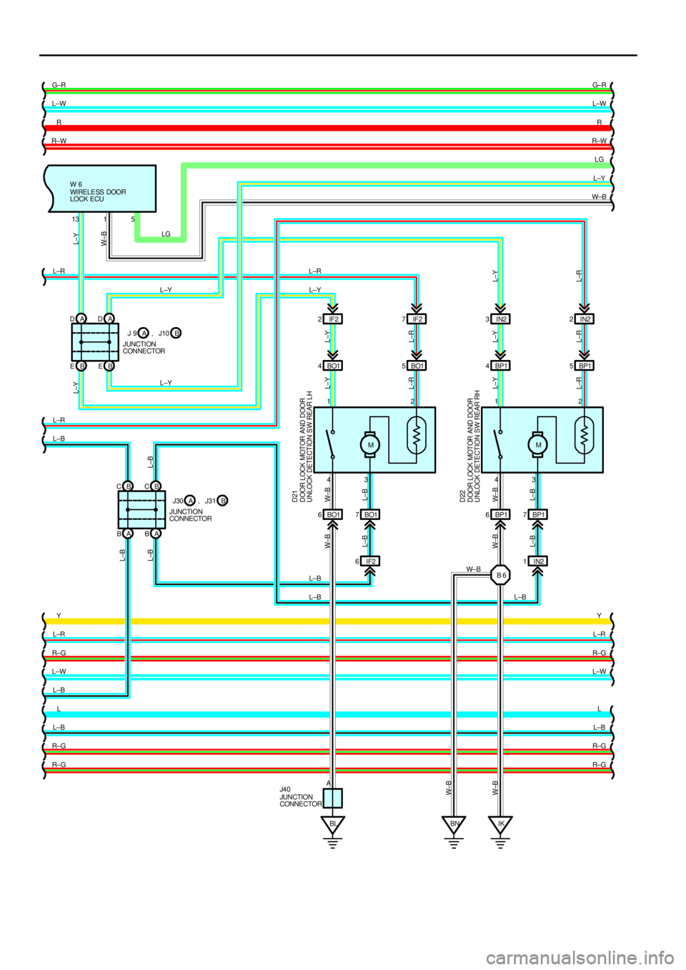
G±R
L±W
R
R±W
L±R
L±R
L±B
Y
L±R
R±G
L±W
L±B
L
L±B
R±G
R±GG± R
L±W
R
R±W
LG
L±Y
W±B
Y
L±R
R±G
L±W
L
L±B
R±G
R±G A DAD
B EBE
B C
A BABB CBO1 4BO15
M
BO1 7
DOOR LOCK MOTOR AND DOOR
UNLOCK DETECTION S W REAR LH D21
L±R L±Y
432 1
L±Y
L±R W± B
L±B
BP1 4 BP15
M
BP1 7
DOOR LOCK MOTOR AND DOOR
UNLOCK DETECTION S W REAR RH D22
L±R L±Y
432 1
L±Y
L±R W± B
L±B
BO1 6 BP16
IF2 6IN21
BL IKBNB 6 IF2 2IF27IN23IN22
L±R L±Y
L±B W±B W±B W±BL±B W±B L±B
L±B L±BW±BL±YL±Y L±R LG
L±Y
L±Y
L±B
L±B L±BW± B 1315
A WIRELE SS DOOR
LOCK ECU W 6
JUNCTION
CONNECTORB A
JUNCTION
CONNECTORB A
JUN CTION
CONNECTOR J4 0
L±Y
J30 , J31 J 9 , J10