2000 TOYOTA CAMRY ECU
[x] Cancel search: ECUPage 1400 of 4770
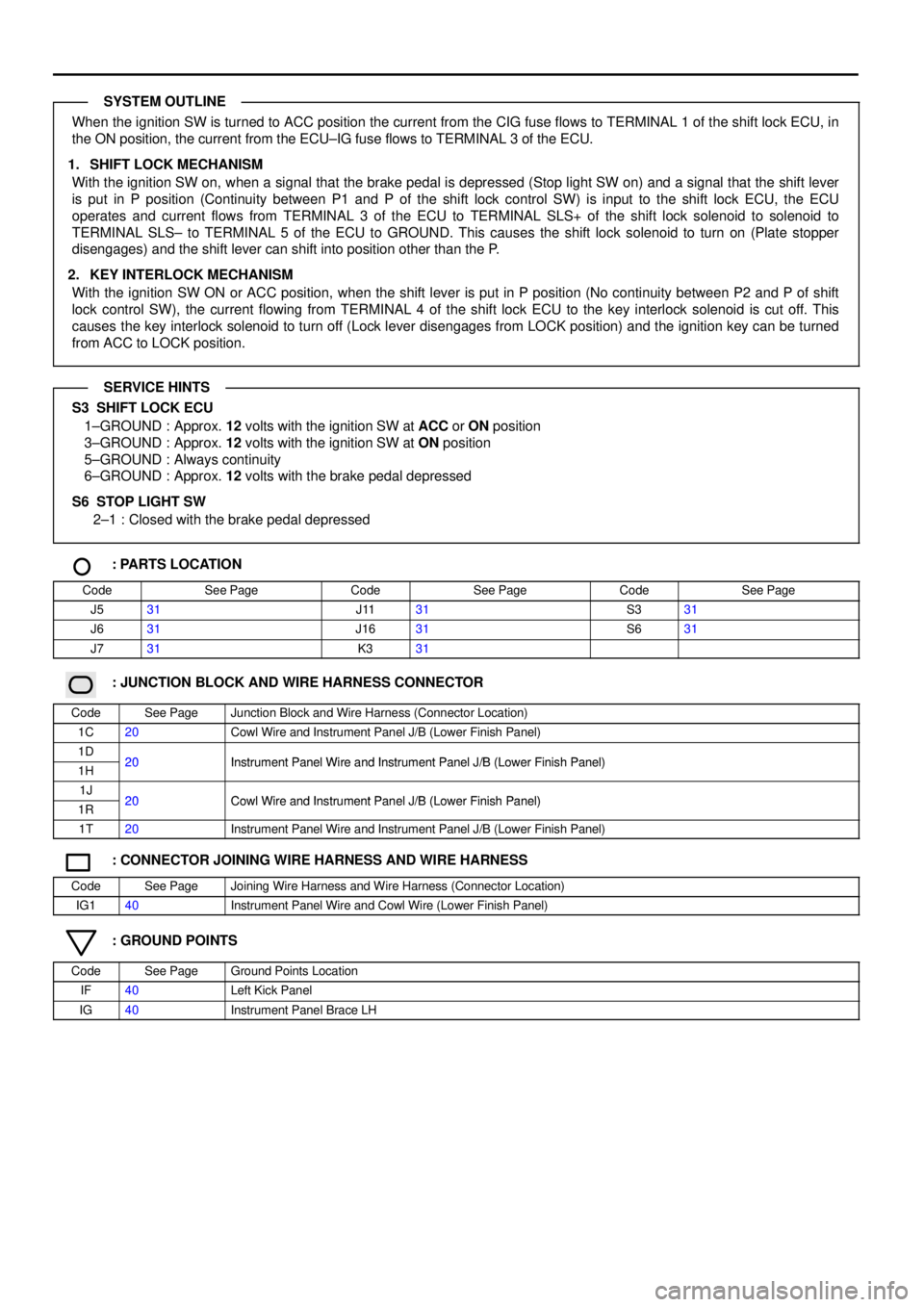
When the ignition SW is turned to ACC position the current from the CIG fuse flows to TERMINAL 1 of the shift lock ECU, in
the ON position, the current from the ECU±IG fuse flows to TERMINAL 3 of the ECU.
1. SHIFT LOCK MECHANISM
With the ignition SW on, when a signal that the brake pedal is depressed (Stop light SW on) and a signal that the shift lever
is put in P position (Continuity between P1 and P of the shift lock control SW) is input to the shift lock ECU, the ECU
operates and current flows from TERMINAL 3 of the ECU to TERMINAL SLS+ of the shift lock solenoid to solenoid to
TERMINAL SLS± to TERMINAL 5 of the ECU to GROUND. This causes the shift lock solenoid to turn on (Plate stopper
disengages) and the shift lever can shift into position other than the P.
2. KEY INTERLOCK MECHANISM
With the ignition SW ON or ACC position, when the shift lever is put in P position (No continuity between P2 and P of shift
lock control SW), the current flowing from TERMINAL 4 of the shift lock ECU to the key interlock solenoid is cut off. This
causes the key interlock solenoid to turn off (Lock lever disengages from LOCK position) and the ignition key can be turned
from ACC to LOCK position.
S3 SHIFT LOCK ECU
1±GROUND : Approx. 12 volts with the ignition SW at ACC or ON position
3±GROUND : Approx. 12 volts with the ignition SW at ON position
5±GROUND : Always continuity
6±GROUND : Approx. 12 volts with the brake pedal depressed
S6 STOP LIGHT SW
2±1 : Closed with the brake pedal depressed
: PARTS LOCATION
CodeSee PageCodeSee PageCodeSee Page
J531J1131S331
J631J1631S631
J731K331
: JUNCTION BLOCK AND WIRE HARNESS CONNECTOR
CodeSee PageJunction Block and Wire Harness (Connector Location)
1C20Cowl Wire and Instrument Panel J/B (Lower Finish Panel)
1D20Instrument Panel Wire and Instrument Panel J/B (Lower Finish Panel)1H20Instrument Panel Wire and Instrument Panel J/B (Lower Finish Panel)
1J20Cowl Wire and Instrument Panel J/B (Lower Finish Panel)1R20Cowl Wire and Instrument Panel J/B (Lower Finish Panel)
1T20Instrument Panel Wire and Instrument Panel J/B (Lower Finish Panel)
: CONNECTOR JOINING WIRE HARNESS AND WIRE HARNESS
CodeSee PageJoining Wire Harness and Wire Harness (Connector Location)
IG140Instrument Panel Wire and Cowl Wire (Lower Finish Panel)
: GROUND POINTS
CodeSee PageGround Points Location
IF40Left Kick Panel
IG40Instrument Panel Brace LH
SYSTEM OUTLINE
SERVICE HINTS
Page 1419 of 4770
AUTO ANTENNA
* 2 : SEPARATE TYPE AMPLIFIER * 1 : BUILT±IN TYPE AMPLIFIER
W±B
AUTO ANTENNA MOTOR
AND RELAY
BN A27 2K 11
1G 61W 5
L±Y L±Y
1H 31D8
B±R
FROM POWER SOURCE SYSTEM (
SEE PAGE 50)
7. 5A
RAD±
NO. 215A
ECU±IG 20A
RADIO
NO. 1
A BABAAAAAC
B BBCBA
1IN1 IN1 3 IN1 4 IN1 5
B 6
IK 3254
6RADIO AND PLAYER R 3
STEREO COMPONENT AMPLIFIER
RADIO AND PLAYER R 4
L±Y
(
*1)
GR
GR
(
*1) L±Y
GR
B±R
JUNCTION
CONNECTORB A L±Y
(
*2)
GR
(
*2)
L±Y
GR
B±R
+B ACC IG ANT
B±R B±R
(
*1)
W±B
W±B B±R
(
*2)R±B
(
*2) GR
(
*2) L±Y
(
*2) B±R
(
*1) GR
(
*1) L±Y
(
*1)
EIH14
IH13
IH18+B
ACC+B
ANT+B
+B
ACC
ANT+B A7
B2B A S 4 , S 5
J1 6 , J174
3
8
8
Page 1427 of 4770
COMBINATION METER
10A
GAUGEFROM POWER SOURCE SYSTEM (
SEE PAGE 50)
1D 27. 5A
DOME
2J 12
1J 1
1G 81W 1
IF2 3IF24IJ17IJ12IJ13IJ16 IG3 6IG3 10 C 7B 14 B11
B 6B3C5C8B15 C6B10 A2A1C2
FUEL
TACHO
SPEEDOMETER
WATER TEMP.
1 II2 2IG33
IF2 1
IH1 JUNCTION
CONNECTOR J 4
JUNCTION
CONNECTOR J28
FUEL SENDER F1 4JUNCTION
CONNECTOR J15JUNCTION
CONNECTOR J1 6
WATER
TEMP.
SENDER W 3
VEHICLE SPEED SENSOR
(
COMBINATION METER) V 2
JUNCTION
CONNECTOR J24
FROM ENGI NE
CONTROL MODULE
TO DOOR
COURTESY SW
TO ENGI NE
CONTROL MODULETO ENGI NE
CONTROL MODULE
TO CRUISE
CONTROL ECU R±L
R±L R±L
V±W
V±W V±W
R R±L R±L
Y±R
G±WY±R
G±W
BR
B±O
L
P
R±W
BR
Y±G
G± R BR BR
BR
B±O
L
P R±L
BR BR
Y±G
G± R
R±L
V±W
R±L FF
DB
232B
DBEE
3
1
FUEL
DOOR
MALFUNCTION
INDICATOR LAMPTRIP METER
ODOMETER
SI SE
IG+
ED : * 1
EC : * 221
DIODE
(
DOME) D10
R±YR R
J21(
*2)
(
*1)
AA C 8
COMBINATION METERB A, C 9 C, C10
TO A/C CONTROL
AS SE MB LY V±W
,
Page 1428 of 4770
5A
STARTER FROM POWER SOURCE SYSTEM (
SEE PAGE 50)
1J 3
IJ1 5IF2 5 IG2 5IG317 IG23
IK2 3 C 9B 2
B 5C10 A4C4C11 A3B7C3A5A12
EB 2 1 II2 11A B
B C
IG1 6
11
IG1 7
12 1
IG
R±Y
B±W
GR
B±O Y±B Y±B
O O
R±W
R±L
P±L
Y±G P±L P±L W±B
Y±G
R±W R±W R±W
R±W W±B
B±W
B±WB±W
B±O
R±W
R±W R±W
R±W PARK /NEUTRAL
POSITION SW P 1
OIL PRESSURE
SW O 1
PARKING
BRAKE SW P 3 CLUTCH START SW C 7
WASHER LEVEL
WARNING SW W 1
JUNCTION
CONNECTOR J 2
BRAKE FLUID
LEVEL WARNING SW B 2
JUNCTION
CONNECTOR J11L
LG
G± O
B5
B B6
2B B
BFROM THEFT
DETERRENT ECU SECURITY
OIL
CRUISE
SEAT BELT
ABS
WASHER LEVEL
REAR LIGHTS
BRAKE
BULB
CHECK
RELAY
TRAC OFF
SLIP
O/D OFF
(
A/T)
(
M/T) JUNCTION
CONNE CTOR J29
(
M/T) (
A/T)
P
N
(
*5)
(
*6) (
*3)
(
*4)
(
*4)PKB BRK
A
TO CRUISE
CONTROL ECU
TO INTEGRATION
RELAY
TO ABS ECU
TO ABS AND TRACTION ECU
TO ABS ACTUATOR AND ECU
TO LI GHT
FAI LURE
SENSORTO ABS AND
TRACTION
ECU
GR
(
A/T)
II2 10
GR
B±O
B±O(
*5 A/T)
(
*6 A/T)
TO O/D
MAIN SWJ 7
JUNCTION
CONNECTORB A, J 8
C 8
COMBINA TION METERB A, C 9 C, C10* 1 : 1 MZ± FE
* 2 : 5S±FE
* 3 : W/O DAYTIME RUNNING LIGHT
* 4 : W/ DAYTIME RUNNING LIGHT
* 5 : TMC MADE
* 6 : TMMK MADE
B 4(
*2) A 18(
*1)
A 8(
*1)
B 14(
*2)
B D 6 , A
DAY TIME RUNNING
LIGHT RELAY (
MAIN)
Page 1430 of 4770
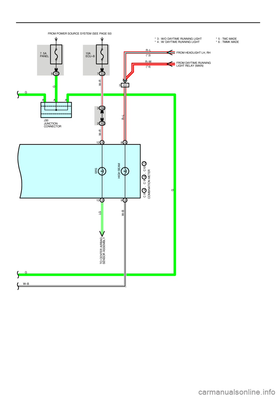
7. 5A
PANEL
1D 510A
ECU±B FROM POWER SOURCE SYSTEM (
SEE PAGE 50)
2J 7
B 12 B8
B 13 B9 1G 2IG1 3
W±R W±R
R±L
G LG
W± B
G
G
W± BR±L
R±W(
*3)
(
*4)FROM HEADLIGHT LH, RH
FROM DAYTIME RUNNING
LIGHT RELAY (
MAIN)
TO CENTER AIRBAG
SENSOR ASSEMBLYSRS
HIGH BEAM
* 3 : W/O DAYTIME RUNNING LIGHT
* 4 : W/ DAYTIME RUNNING LIGHT
G
AAA
JUNCTION
CONNECTOR J30
C 8
COMBINATION METERB A, C 9 C, C10
* 5 : TMC MADE
* 6 : TMMK MADE
1W 3
Page 1435 of 4770
RADIATOR FAN AND CONDENSER FAN
40A
AM130A
CDS
15A
ECU±IG
1A 61K 1
15 2311
1115 23
4 11
111 13 4252K 6
2B 22F423 14
2F 22G1 30A
RDI
2 3
1 21 1 2
E 4 E 32C 12G 72C22H2
1B 11K 2
EA1 1IK1 5 IK2 7
II1 1
EA1 2 F 1F2D1
A 1
EB1 2
B±G B±R
B±R
B±R
W±B W±BB±R W
B±Y B±R
L G± W
W± BL±W L±W W± B
W±BR G±W
B±R L
B±R L
B±WL±Y
L L±Y
L
W± B
W± BW±B
W±BB±R W±RB±R G±W
(
1 MZ± FE) (
1 MZ± FE)L
(
1MZ±FE)
(
1MZ± FE) (
1 MZ± FE)
(
5S±FE)
(
1 MZ± FE)
(
5S±FE)
21
2
1
A 3
A/C SINGLE
PRESSURE SW W 4
WAT ER TEMP.
SW NO. 1
D 3
DIODE
(
A/C) R 1
RADIATOR
FAN MOTOR
WATER
TEMP. SW NO. 2 W 5
A/C CONDENSER
FAN MOTOR A 1FUSIBLE LINK
BL OC KIGNITION SW I16
FAN
NO. 1
RELAY
ENGINE
MAIN
RELAY
FROM MG CLT
RELAY
FA N
NO. 3
RELAY
FAN NO. 2 RELAY
BATTERY 100A
AL T
FL MAI N
3. 0W
MGC
(
1MZ±FE) 24AM1ACC
IG1
1 22 1
2J 13
II2 1
G±W G±W
CF
(
1MZ±FE) (
1MZ±FE)
E 29 D F 4
A, F 7
F 9 F
* 1 : AUTOMA TI C A/ C
* 2 : MANUAL A/C
E11
ENGINE CONTROL
MODULEE ,
A12
A/C AMPLIFIERA
A34
A/C CONTROL
AS SE MB LYB
A 12(
*2) B 2(
*1)M M
Page 1436 of 4770

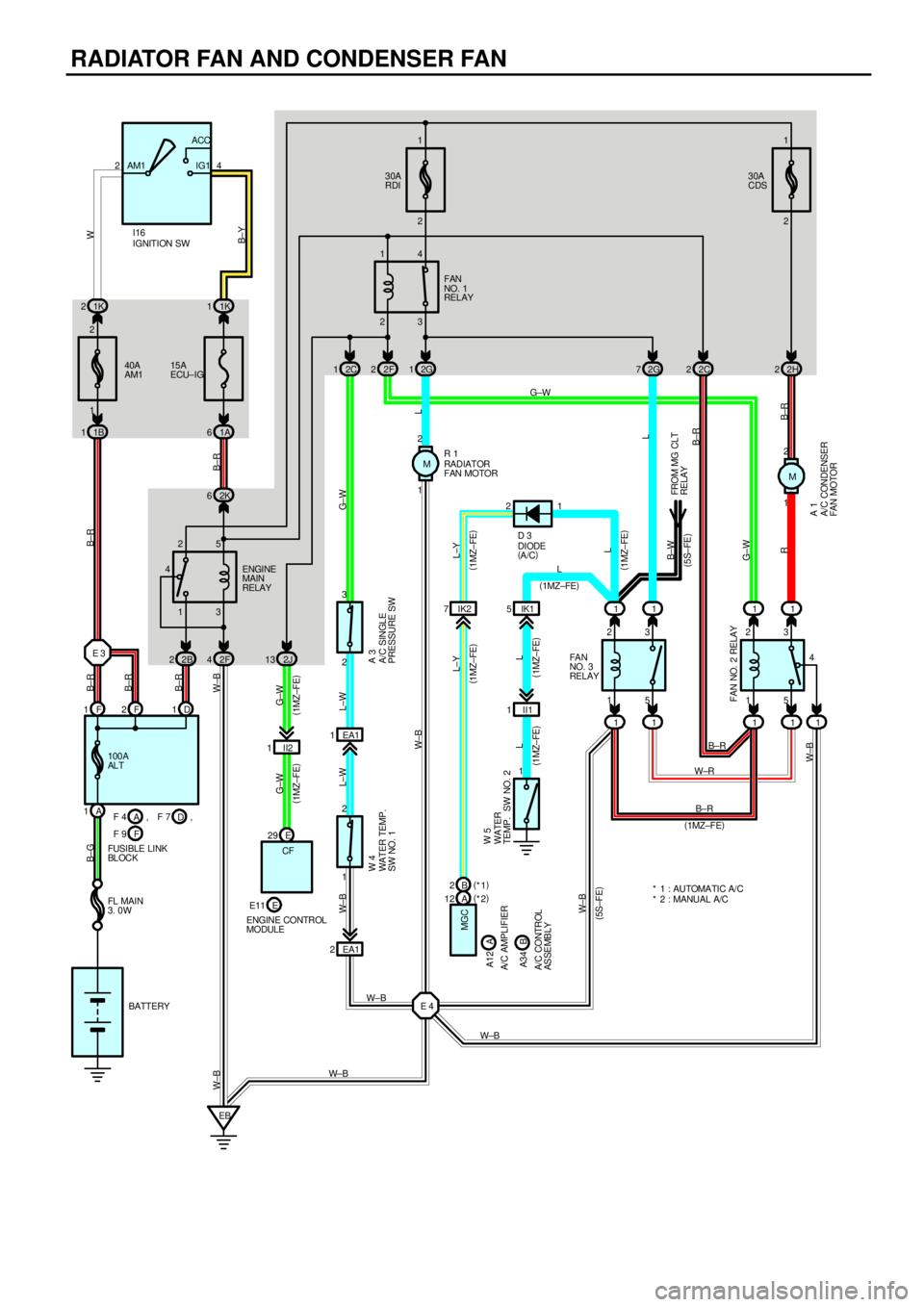
FAN MOTOR OPERATION (1MZ±FE)
With the ignition SW turned on, the current through the ECU±IG fuse flows to the FAN NO.1 relay (Coil side), FAN NO.2 relay
(Coil side) and FAN NO.3 relay (Coil side). Furthermore, the current through the FAN NO.1 relay (Coil side) or the FAN NO.2
relay (Coil side) flows to TERMINAL 3 of the A/C single pressure SW to TERMINAL 2 to TERMINAL 2 of the water temp. SW
No.1 to TERMINAL 1 to GROUND, causing the FAN NO.1 relay to turn off and the FAN NO.2 relay to turn on.
1. LOW SPEED OPERATION
Only when the A/C system is activated or the water temp. SW No.2 is turned on, the A/C condenser fan motor and the
radiator fan motor rotates at low speed.
When the A/C system is activated, the current from ECU±IG fuse flows to the FAN NO.3 relay (Coil side) to TERMINAL 1 of
the diode (A/C) to TERMINAL 2 to TERMINAL (A)12 of the A/C amplifier (Manual A/C) or (B) 2 of the A/C control assembly
(Automatic A/C) causing the FAN NO.3 relay to turn on. As a result, the current through the CDS fuse flows to TERMINAL 2
of the A/C condenser fan motor to TERMINAL 1 to TERMINAL 3 of the FAN NO.2 relay to TERMINAL 5 to TERMINAL 5 of
the FAN NO.3 relay to TERMINAL 3 to TERMINAL 2 of the radiator fan motor to TERMINAL 1 to GROUND. As this flowing in
series for the motors, the motors rotate at low speed.
When the water temp. SW No.2 is turned on, the current from ECU±IG fuse flows to the FAN NO.3 relay (Coil side) to
TERMINAL 1 of the water temp. SW No.2 to GROUND, causing the FAN NO.3 relay to turn on. As a result, the current
through the CDS fuse flows the same route as above, rotating the motors at low speed.
2. HIGH SPEED OPERATION
Only when the A/C single pressure SW is turned off or the water temp. SW No.1 is turned off, the A/C condenser fan motor
and the radiator fan motor rotate at high speed.
When the A/C single pressure SW is turned off, the current from the RDI fuse flows to the FAN NO.1 relay (Point side) to
TERMINAL 2 of the radiator fan motor to TERMINAL 1 to GROUND. At the same time, the current from the CDS fuse flows
to TERMINAL 2 of the A/C condenser fan motor to TERMINAL 1 to TERMINAL 3 of the FAN NO.2 relay to TERMINAL 4 to
GROUND.
As the current flowing in parallel for the motors as above, the motors rotate at high speed.
FAN MOTOR OPERATION (5S±FE)
With the ignition SW turned on, the current through the ECU±IG fuse flows to the FAN NO.1 relay (Coil side), FAN NO.2 relay
(Coil side). furthermore, the current through the FAN NO.1 relay (Coil side) or the FAN NO.2 relay (Coil side) flows to
TERMINAL 3 of the A/C single pressure SW to TERMINAL 2 to TERMINAL 2 of the water temp. SW No.1 to TERMINAL 1 to
GROUND, causing the FAN NO.1 relay to turn off and the FAN NO.2 relay to turn on.
1. LOW SPEED OPERATION
When the ignition SW is turned on and the A/C system is activated, the A/C condenser fan motor and the radiator fan motor
rotates at low speed.
When the A/C system is activated, the current from MG CLT relay flows to the FAN NO.3 relay (Coil side) to GROUND,
causing the FAN NO.3 relay to turn on. As a result, the current through the CDS fuse flows to TERMINAL 2 of the A/C
condenser fan motor to TERMINAL 1 to TERMINAL 3 of the FAN NO.2 relay to TERMINAL 5 to TERMINAL 5 of the FAN
NO.3 relay to TERMINAL 3 to TERMINAL 2 of the radiator fan motor to TERMINAL 1 to GROUND. As this flowing in series
for the motors, the motors rotate at low speed.
2. HIGH SPEED OPERATION
Only when the A/C single pressure SW is turned off or the water temp. SW No.1 is turned off, the A/C condenser fan motor
and the radiator fan motor rotate at high speed.
When the A/C single pressure SW is turned off, the current from the RDI fuse flows to the FAN NO.1 relay (Point side) to
TERMINAL 2 of the radiator fan motor to TERMINAL 1 to GROUND. At the same time, the current from the CDS fuse flows
to TERMINAL 2 of the A/C condenser fan motor to TERMINAL 1 to TERMINAL 3 of the FAN NO.2 relay to TERMINAL 4 to
GROUND.
As the current flowing in parallel for the motors as above, the motors rotate at high speed.
A3 A/C SINGLE PRESSURE SW
3±2 : Open above approx. 15.5 kgf/cm2
(224 psi, 1520 kpa)
Closed below approx. 12.5 kgf/cm2 (181 psi, 1225 kpa)
W4 WATER TEMP. SW NO.1
2±1 : Open above approx. 95°C (203° F)
W5 WATER TEMP. SW NO.2 (1MZ±FE)
1±GROUND : Closed above approx. 90°C (194°F)
SYSTEM OUTLINE
SERVICE HINTS
Page 1439 of 4770
AIR CONDITIONING (AUTOMATIC A/C)
23 41510A
HEATER FROM POWER SOURCE SYSTEM (
SEE PAGE 50)
1W 2
6 2
IG FUS IBL E
LINK BLOCK10A
ECU±B
2J 7
L±B
HTR
RELAY
A/C BLOWER MOTOR
LINEAR CONTROLLER A33
50A HTR
1F 8
1R 3
11111
EB23 15
MG CLT
RELAY
11 11
I 8 2K 5
2C 91W 3
1V 10
21
EB2 1
I 73 L±B L±B
L±R L±R B±W
AA A4
2
B±W
L±B W±B
W±B
W±B W±R
L±B
L±B
L±B
W± R W±R
L±B
L±W
L±W
B±W
L±R
L±W W± B
L±R
B±W
B±W B±W
W±B
L±W
1
W±B W±B
W±B
W±B
L±B W± B
W±B
W±B JUNCTION
CONNECTOR J11 BLOWER MOTOR B 3
BLOWER RESISTOR
(
LOW SPEED) B 8
B±WA A
AJUNCTION
CONNECTOR J32
+B
VM
SI
GND
IIA
W± B
I 7W±B M