Page 3381 of 4770

B06722
Battery
B06545
B06543
Hose Clipper
Air Drain Hose
± EMISSION CONTROL (1MZ±FE)EVAPORATIVE EMISSION (EVAP) CONTROL SYSTEM
EC±7
1422 Author�: Date�:
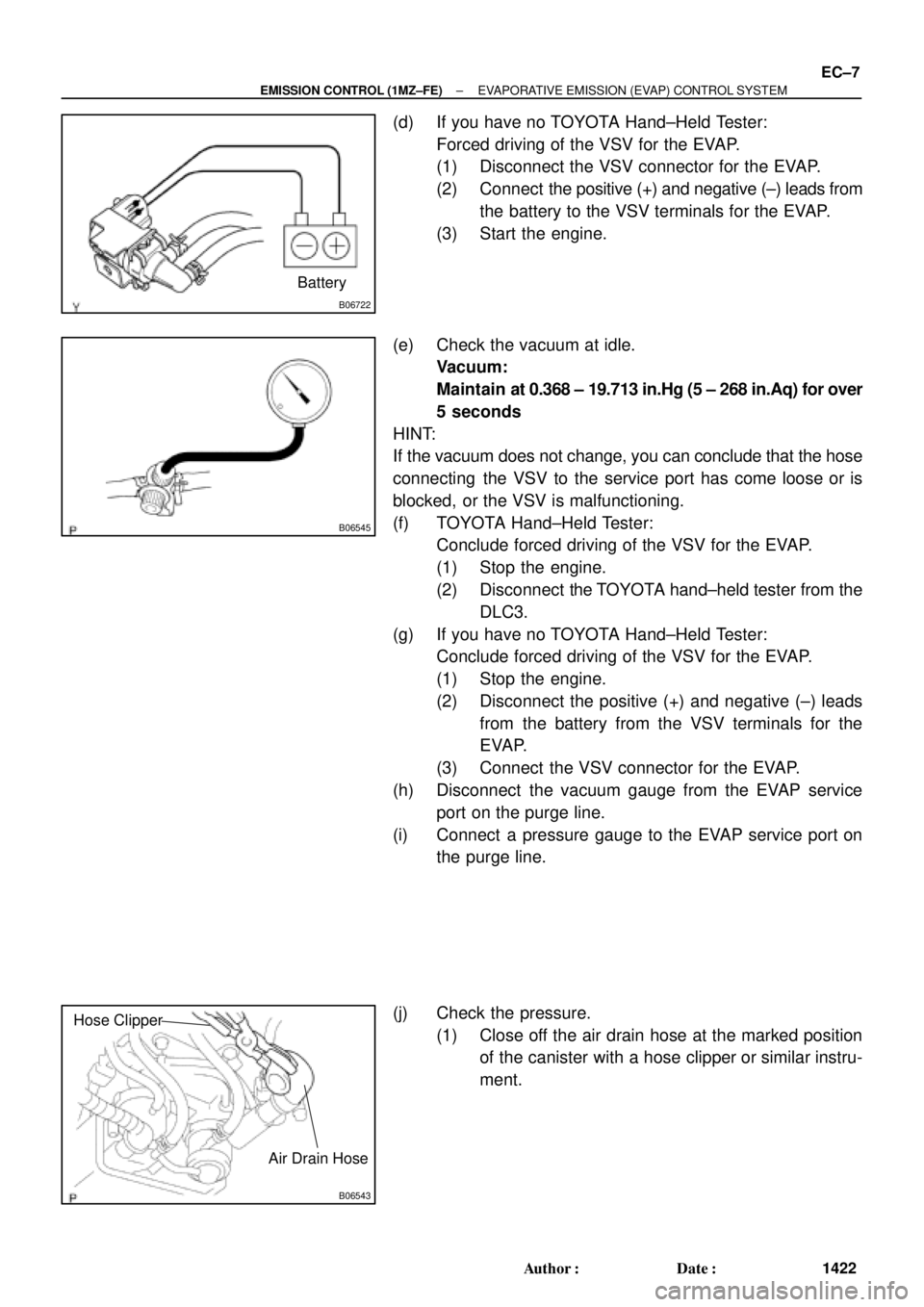
(d) If you have no TOYOTA Hand±Held Tester:
Forced driving of the VSV for the EVAP.
(1) Disconnect the VSV connector for the EVAP.
(2) Connect the positive (+) and negative (±) leads from
the battery to the VSV terminals for the EVAP.
(3) Start the engine.
(e) Check the vacuum at idle.
Vacuum:
Maintain at 0.368 ± 19.713 in.Hg (5 ± 268 in.Aq) for over
5 seconds
HINT:
If the vacuum does not change, you can conclude that the hose
connecting the VSV to the service port has come loose or is
blocked, or the VSV is malfunctioning.
(f) TOYOTA Hand±Held Tester:
Conclude forced driving of the VSV for the EVAP.
(1) Stop the engine.
(2) Disconnect the TOYOTA hand±held tester from the
DLC3.
(g) If you have no TOYOTA Hand±Held Tester:
Conclude forced driving of the VSV for the EVAP.
(1) Stop the engine.
(2) Disconnect the positive (+) and negative (±) leads
from the battery from the VSV terminals for the
EVAP.
(3) Connect the VSV connector for the EVAP.
(h) Disconnect the vacuum gauge from the EVAP service
port on the purge line.
(i) Connect a pressure gauge to the EVAP service port on
the purge line.
(j) Check the pressure.
(1) Close off the air drain hose at the marked position
of the canister with a hose clipper or similar instru-
ment.
Page 3385 of 4770
EC0AW±01
S05477
DisconnectOhmmeter
E2 VC
B01480
E2(±)
VC(+)
± EMISSION CONTROL (1MZ±FE)EXHAUST GAS RECIRCULATION (EGR) SYSTEM
EC±11
1426 Author�: Date�:
EXHAUST GAS RECIRCULATION
(EGR) SYSTEM
INSPECTION
1. INSPECT EGR SYSTEM (See page DI±358)
2. INSPECT EGR VALVE POSITION SENSOR
(a) Inspect the resistance of the EGR valve position sensor.
(1) Disconnect the EGR valve position sensor connec-
tor.
(2) Using an ohmmeter, measure the resistance be-
tween the terminals VC and E2.
Resistance: 1.5 ± 4.3 kW
If the resistance is not as specified, replace the EGR valve posi-
tion sensor.
(3) Reconnect the EGR valve position sensor connec-
tor.
(b) Inspect the power output voltage of the EGR valve posi-
tion sensor.
(1) Disconnect the vacuum hose from the EGR valve.
(2) Turn the ignition switch ON.
(3) Connect a voltmeter to terminals VC and E2 of the
ECM, and measure the power source voltage.
Voltage: 4.5 ± 5.5 V
Page 3386 of 4770

B01482
Disconnect
E2(±) EGLS(+)
S05452
S05455
(1)
(2)
(3)
EC±12
± EMISSION CONTROL (1MZ±FE)EXHAUST GAS RECIRCULATION (EGR) SYSTEM
1427 Author�: Date�:
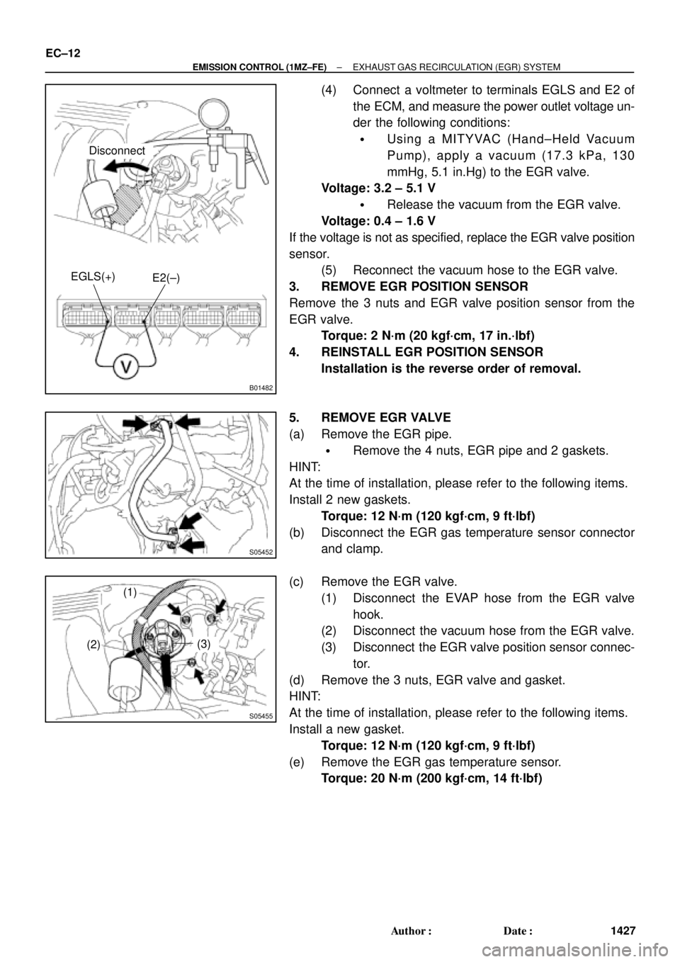
(4) Connect a voltmeter to terminals EGLS and E2 of
the ECM, and measure the power outlet voltage un-
der the following conditions:
�Using a MITYVAC (Hand±Held Vacuum
Pump), apply a vacuum (17.3 kPa, 130
mmHg, 5.1 in.Hg) to the EGR valve.
Voltage: 3.2 ± 5.1 V
�Release the vacuum from the EGR valve.
Voltage: 0.4 ± 1.6 V
If the voltage is not as specified, replace the EGR valve position
sensor.
(5) Reconnect the vacuum hose to the EGR valve.
3. REMOVE EGR POSITION SENSOR
Remove the 3 nuts and EGR valve position sensor from the
EGR valve.
Torque: 2 N´m (20 kgf´cm, 17 in.´lbf)
4. REINSTALL EGR POSITION SENSOR
Installation is the reverse order of removal.
5. REMOVE EGR VALVE
(a) Remove the EGR pipe.
�Remove the 4 nuts, EGR pipe and 2 gaskets.
HINT:
At the time of installation, please refer to the following items.
Install 2 new gaskets.
Torque: 12 N´m (120 kgf´cm, 9 ft´lbf)
(b) Disconnect the EGR gas temperature sensor connector
and clamp.
(c) Remove the EGR valve.
(1) Disconnect the EVAP hose from the EGR valve
hook.
(2) Disconnect the vacuum hose from the EGR valve.
(3) Disconnect the EGR valve position sensor connec-
tor.
(d) Remove the 3 nuts, EGR valve and gasket.
HINT:
At the time of installation, please refer to the following items.
Install a new gasket.
Torque: 12 N´m (120 kgf´cm, 9 ft´lbf)
(e) Remove the EGR gas temperature sensor.
Torque: 20 N´m (200 kgf´cm, 14 ft´lbf)
Page 3393 of 4770

EM07X±05
S04994
CO/HC Meter
± ENGINE MECHANICAL (5S±FE)CO/HC
EM±1
1173 Author�: Date�:
CO/HC
INSPECTION
HINT:
This check is used only to determine whether or not the idle CO/
HC complies with regulations.
1. INITIAL CONDITIONS
(a) Engine at normal operating temperature
(b) Air cleaner installed
(c) All pipes and hoses of air induction system connected
(d) All accessories switched OFF
(e) All vacuum lines properly connected
HINT:
All vacuum hoses for EGR system, etc. should be properly con-
nected.
(f) SFI system wiring connectors fully plugged
(g) Ignition timing checked correctly
(h) Transmission in neutral position
(i) Tachometer and CO/HC meter calibrated by hand
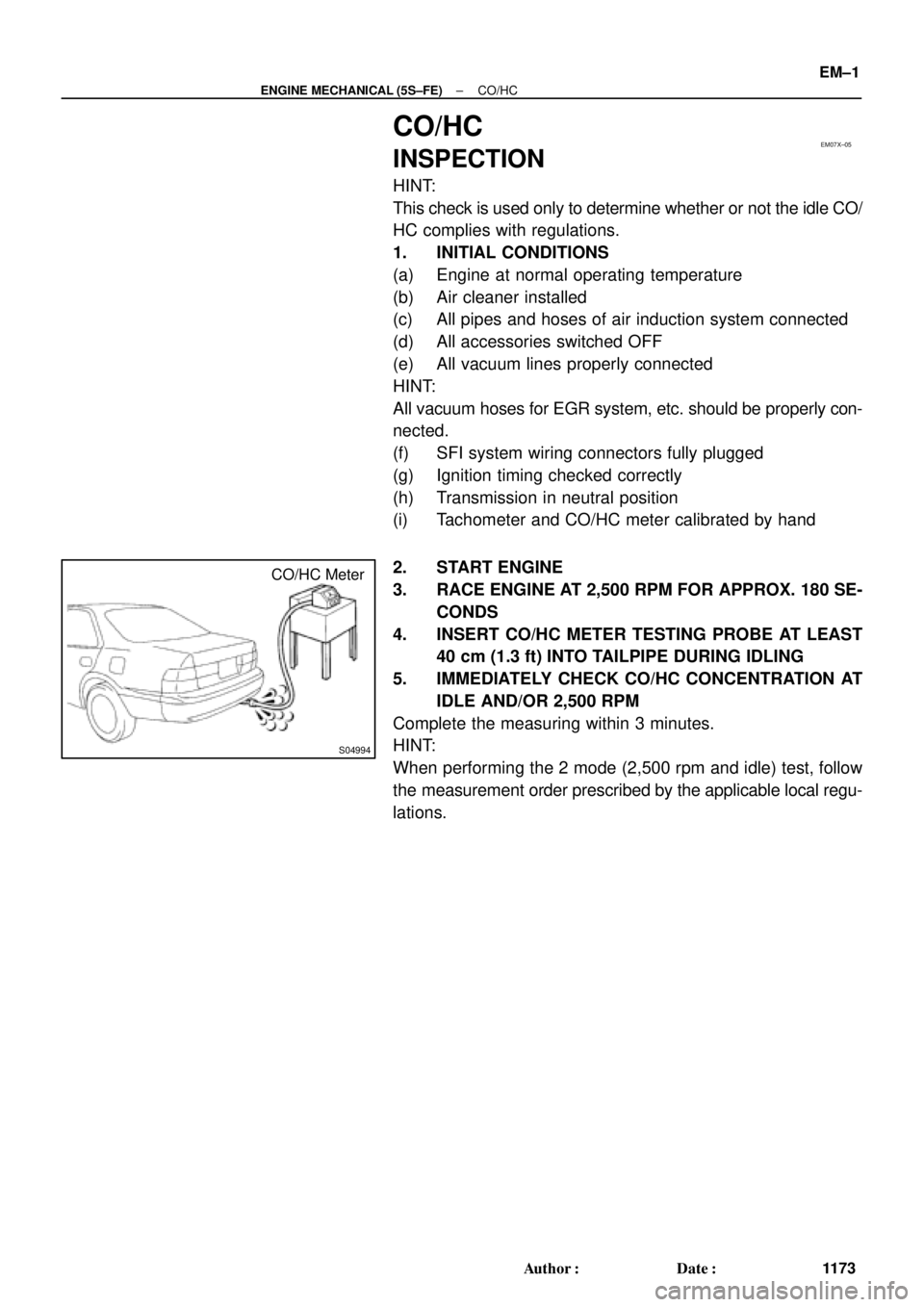
2. START ENGINE
3. RACE ENGINE AT 2,500 RPM FOR APPROX. 180 SE-
CONDS
4. INSERT CO/HC METER TESTING PROBE AT LEAST
40 cm (1.3 ft) INTO TAILPIPE DURING IDLING
5. IMMEDIATELY CHECK CO/HC CONCENTRATION AT
IDLE AND/OR 2,500 RPM
Complete the measuring within 3 minutes.
HINT:
When performing the 2 mode (2,500 rpm and idle) test, follow
the measurement order prescribed by the applicable local regu-
lations.
Page 3394 of 4770

EM±2
± ENGINE MECHANICAL (5S±FE)CO/HC
1174 Author�: Date�:
If the CO/HC concentration does not comply with regulations,
troubleshoot in the order given below.
(1) Check oxygen sensor operation.
(See page DI±66)
(2) See the table below for possible causes, then in-
spect and correct the applicable causes if neces-
sary.
COHCSymptomCauses
NormalHighRough idle1. Faulty ignitions:
� Incorrect timing
� Fouled, shorted or improperly gapped plugs
� Open or crossed hi
gh±tension cords� Oen or crossed high±tension cords
2. Incorrect valve clearance
3. Leaky EGR valve
4. Leaky intake and exhaust valves
5. Leaky cylinder
LowHighRough idle
(Fluctuating HC reading)1. Vacuum leaks:
� PCV hose
� EGR valve
� Intake manifold
� Throttle body
� IAC valve
� Brake booster line
2. Lean mixture causing misfire
HighHighRough idle
(Black smoke from exhaust)1. Restricted air filter
2. Faulty SFI system
� Faulty pressure regulator
� Defective ECT sensor
� Defective IAT sensor
� Faulty ECM
� Faulty injector
� Faulty throttle position sensor
� MAP sensor
Page 3402 of 4770

EM081±05
S05331
EM±10
± ENGINE MECHANICAL (5S±FE)IDLE SPEED
1182 Author�: Date�:
IDLE SPEED
INSPECTION
1. INITIAL CONDITIONS
(a) Engine at normal operating temperature
(b) Air cleaner installed
(c) All pipes and hoses of air induction system connected
(d) All vacuum lines properly connected
(e) SFI system wiring connectors fully plugged
(f) All operating accessories switched OFF
(g) Ignition timing check correctly
(h) Transmission in neutral position
(i) Air conditioning switched OFF
2. CONNECT TOYOTA HAND±HELD TESTER OR OBDII
SCAN TOOL
(a) Remove the fuse cover on the instrument panel.
(b) Connect a TOYOTA hand±held tester or OBDII scan tool
to the DLC3.
(c) Please refer to the TOYOTA hand±held tester or OBDII
scan tool operator's manual for further details.
3. INSPECT IDLE SPEED
(a) Race the engine at 2,500 rpm for approx. 90 seconds.
(b) Check the idle speed.
Idle speed (w/ Cooling fan OFF): 700 ± 50 rpm
If the idle speed is not as specified, check the IAC valve and air
intake system.
4. DISCONNECT TOYOTA HAND±HELD TESTER OR
OBDII SCAN TOOL
Page 3423 of 4770
A07358
Ground Wire
MAP Sensor
Vacuum Hose
Brake Booster
Vacuum Hose
Intake
Manifold
Air Hose for Air Assist System (California)
Intake Manifold
Stay
Injector
(Except California)
Knock Sensor 1
ConnectorPCV HoseVSV Connector
for EGR
VSV for EGREGR Valve and Vacuum
Modulator
Fuel Inlet Hose
Fuel Pulsation Damper
� O±Ring
Injector
(California)Injector
Connector Spacer
Insulator
N´m (kgf´cm, ft´lbf)
� Non±reusable part
� Gasket
� Insulator� Grommet
� O±Ring � Gasket� Gasket
* For use with SST
19 (195, 14)
34 (350, 25)* 29 (300, 21)
: Specified torque
x 6
Engine Wire
13 (130, 9)
Spacer
± ENGINE MECHANICAL (5S±FE)CYLINDER HEAD
EM±31
1203 Author�: Date�:
Page 3426 of 4770

S05548
Wire
Clamp
A01564(c)(d)
(e)
A07364
ConnectorClamp
EM±34
± ENGINE MECHANICAL (5S±FE)CYLINDER HEAD
1206 Author�: Date�:
(j) California:
Disconnect the A/F sensor connector for the wiring side
from the bracket on the LH engine hanger.
(k) Except California:
Disconnect the heated oxygen sensor (bank 1 sensor 1)
connector for the wiring side from the bracket on the LH
engine hanger.
5. REMOVE THROTTLE BODY (See page SF±32)
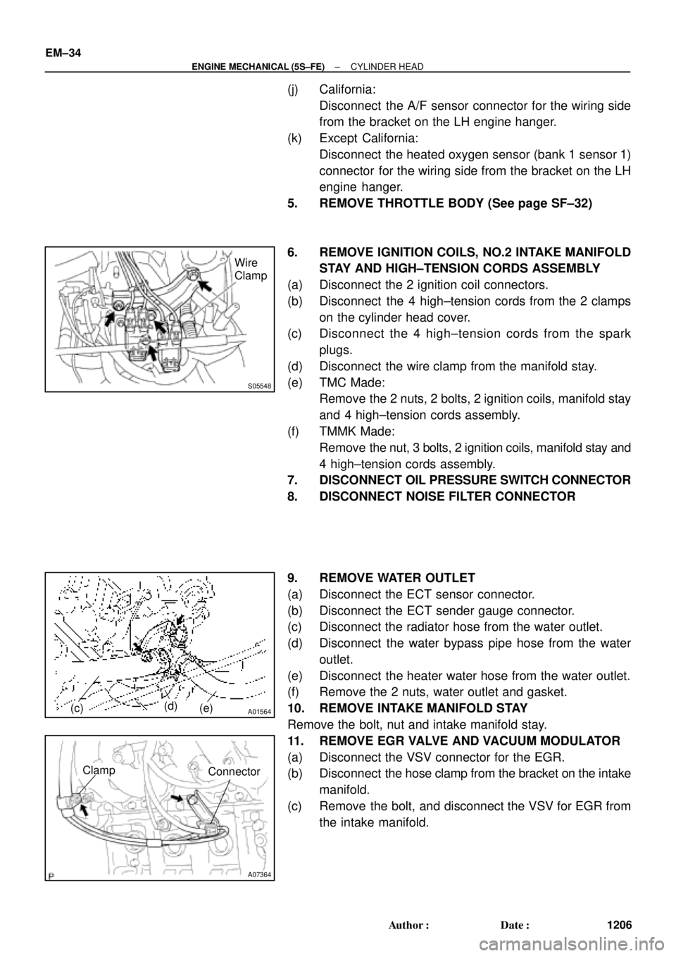
6. REMOVE IGNITION COILS, NO.2 INTAKE MANIFOLD
STAY AND HIGH±TENSION CORDS ASSEMBLY
(a) Disconnect the 2 ignition coil connectors.
(b) Disconnect the 4 high±tension cords from the 2 clamps
on the cylinder head cover.
(c) Disconnect the 4 high±tension cords from the spark
plugs.
(d) Disconnect the wire clamp from the manifold stay.
(e) TMC Made:
Remove the 2 nuts, 2 bolts, 2 ignition coils, manifold stay
and 4 high±tension cords assembly.
(f) TMMK Made:
Remove the nut, 3 bolts, 2 ignition coils, manifold stay and
4 high±tension cords assembly.
7. DISCONNECT OIL PRESSURE SWITCH CONNECTOR
8. DISCONNECT NOISE FILTER CONNECTOR
9. REMOVE WATER OUTLET
(a) Disconnect the ECT sensor connector.
(b) Disconnect the ECT sender gauge connector.
(c) Disconnect the radiator hose from the water outlet.
(d) Disconnect the water bypass pipe hose from the water
outlet.
(e) Disconnect the heater water hose from the water outlet.
(f) Remove the 2 nuts, water outlet and gasket.
10. REMOVE INTAKE MANIFOLD STAY
Remove the bolt, nut and intake manifold stay.
11. REMOVE EGR VALVE AND VACUUM MODULATOR
(a) Disconnect the VSV connector for the EGR.
(b) Disconnect the hose clamp from the bracket on the intake
manifold.
(c) Remove the bolt, and disconnect the VSV for EGR from
the intake manifold.