Page 4161 of 4770
SF08G±03
B06550
VSV for Vapor Pressure
Sensor Connector
VSV for Vapor
Pressure Sensor
Vacuum Hose
Charcoal Canister
± SFI (1MZ±FE)VSV FOR VAPOR PRESSURE SENSOR
SF±61
1560 Author�: Date�:
VSV FOR VAPOR PRESSURE SENSOR
COMPONENTS
Page 4164 of 4770
SF0Z9±01
B06554
Charcoal Canister Vapor Pressure Sensor
(Type A)Vapor Pressure Sensor
(Type B)
Vapor Pressure Sensor
Connector
Vacuum hose
SF±64
± SFI (1MZ±FE)VAPOR PRESSURE SENSOR
1563 Author�: Date�:
VAPOR PRESSURE SENSOR
COMPONENTS
Page 4165 of 4770
SF08J±04
B00801
Disconnect
VC
E2Voltmeter
B06389
Type BDisconnect Vacuum
VacuumAir
PTNKE2 ECMType A
Disconnect
Air
± SFI (1MZ±FE)VAPOR PRESSURE SENSOR
SF±65
1564 Author�: Date�:
INSPECTION
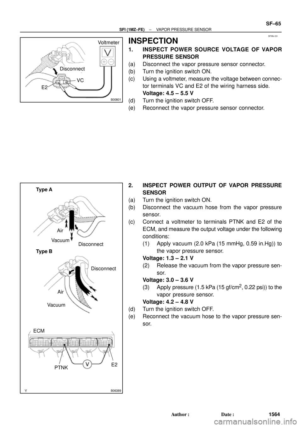
1. INSPECT POWER SOURCE VOLTAGE OF VAPOR
PRESSURE SENSOR
(a) Disconnect the vapor pressure sensor connector.
(b) Turn the ignition switch ON.
(c) Using a voltmeter, measure the voltage between connec-
tor terminals VC and E2 of the wiring harness side.
Voltage: 4.5 ± 5.5 V
(d) Turn the ignition switch OFF.
(e) Reconnect the vapor pressure sensor connector.
2. INSPECT POWER OUTPUT OF VAPOR PRESSURE
SENSOR
(a) Turn the ignition switch ON.
(b) Disconnect the vacuum hose from the vapor pressure
sensor.
(c) Connect a voltmeter to terminals PTNK and E2 of the
ECM, and measure the output voltage under the following
conditions:
(1) Apply vacuum (2.0 kPa (15 mmHg, 0.59 in.Hg)) to
the vapor pressure sensor.
Voltage: 1.3 ± 2.1 V
(2) Release the vacuum from the vapor pressure sen-
sor.
Voltage: 3.0 ± 3.6 V
(3) Apply pressure (1.5 kPa (15 gf/cm
2, 0.22 psi)) to the
vapor pressure sensor.
Voltage: 4.2 ± 4.8 V
(d) Turn the ignition switch OFF.
(e) Reconnect the vacuum hose to the vapor pressure sen-
sor.
Page 4166 of 4770
SF08K±03
B06390
VSV Connector for
EVAP
Ground Cable
PCV Hose
Air Intake Chamber
Assembly
ECT Sensor
Connector ECT Sender
Gauge ConnectorEGR Valve Position
Sensor Connector
IAC Valve
Connector
VSV Connector
for EGR
VSV Connector for ACIS
Engine Wire
Engine Coolant
Reservoir HoseAir Assist Hose
Water Bypass Hose No.2 EGR Pipe
Throttle Position
Sensor Connector
No.1 Engine
HangerBrake Booster
Vacuum Hose Air Intake Chamber Stay
Water OutletPS Pressure Tube
�Gasket
19.5 (200, 14)
39 (400, 19)12 (120, 19)
15 (150, 11)
�Gasket
43 (440, 32)
Ground Starp
DLC1
�Gasket
15 (150, 11)
Grand Strap
Connector
�Gasket
39 (400, 29)
V±Bank Cover
Accelerator Cable
Throttle Cable
Air Cleaner
Hose
Purge HoseEGR Gas Temperature
Sensor Connector
Vacuum
HoseWater Bypass Hose
Fuel Inlet Hose
Heater Hose
Intake Manifold Assembly
Injector Connector x 9
Knock Sensor
Connector
Upper Radiator
Hose
Engine
Wire
Band
High±Tension Cord
Set �Gasket
: Specified torque
�Non±reusable partN´m (kgf´cm, ft´lbf)
�Retainer
Knock Sensor
SF±66
± SFI (1MZ±FE)KNOCK SENSOR
1565 Author�: Date�:
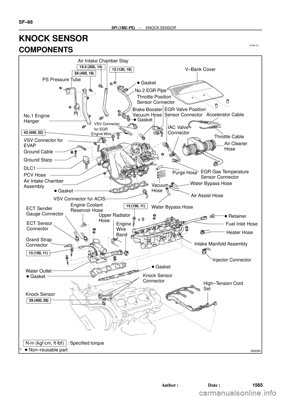
KNOCK SENSOR
COMPONENTS
Page 4556 of 4770
TSB
Technical Service
BULLETIN
June 11, 1999
EG004-99
Toyota Supports ASE Certification
ENGINE
Title:
DIAGNOSTIC TR OUBLE CODE P0446
Models:
'99 Avalon, Camry & Solara
Page 1of 2
Parts
InformationPREVIOUS PART NUMBER CURRENT PART NUMBER
PART NAME
N/A25852-20010 Valve, Vacuum Control with Hoses
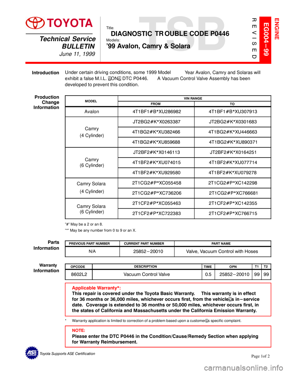
IntroductionUnder certain driving conditions, some 1999 Model
Year Avalon, Camry and Solaras will
exhibit a false M.I.L.
ON DTC P0446.
A Vacuum Control Valve Assembly has been
developed to prevent this condition.
Production
Change
Information
º#º May be a 2 or an 8.
º*º May be any number from 0 to 9 or an X.
MODELVIN RANGE
FROM
TO
Avalon
4T1BF1#B*XU286982 4T1BF1#B*XU307913
Camry
(4 Cylinder)JT2BG2#K*X0263387 JT2BG2#K*X0301683
4T1BG2#K*XU382466 4T1BG2#K*XU446663
4T1BG2#K*XU859688 4T1BG2#K*XU890371
Camry
(6 Cylinder)JT2BF2#K*X0146113 JT2BF2#K*X0164251
4T1BF2#K*XU074015 4T1BF2#K*XU077714
4T1BF2#K*XU929580 4T1BF2#K*XU079278
Camry Solara
(4 Cylinder)2T1CG2#P*XC055458 2T1CG2#P*XC142298
2T1CG2#P*XC736206 2T1CG2#P*XC766681
Camry Solara
(6 Cylinder)2T1CF2#P*XC055463 2T1CF2#P*XC142355
2T1CF2#P*XC722383 2T1CF2#P*XC766715
Applicable Warranty*:
This repair is covered under the Toyota Basic Warranty. This warranty is in effect
for 36 months or 36,000 miles, whichever occurs first, from the vehicle
s in-service
date. Coverage is extended to 36 months or 50,000 miles, whichever occurs first, in
the states of California and Massachusetts under the California Emission Warranty.
*Warranty application is limited to correction of a problem based upon a customers specific complaint.
Warranty
InformationOPCODEDESCRIPTION
TIME
OPNT1
T2
8602L2 Vacuum Control Valve 0.5 25852-20010 99 99
NOTE:
Please enter the DTC P0446 in the Condition/Cause/Remedy Section when applying
for Warranty Reimbursement.
REVISED
TOYOTA
Page 4557 of 4770
DIAGNOSTIC TROUBLE CODE P0446 ± EG004-99 Revised June 11, 1999
Page 2 of 2
Repair
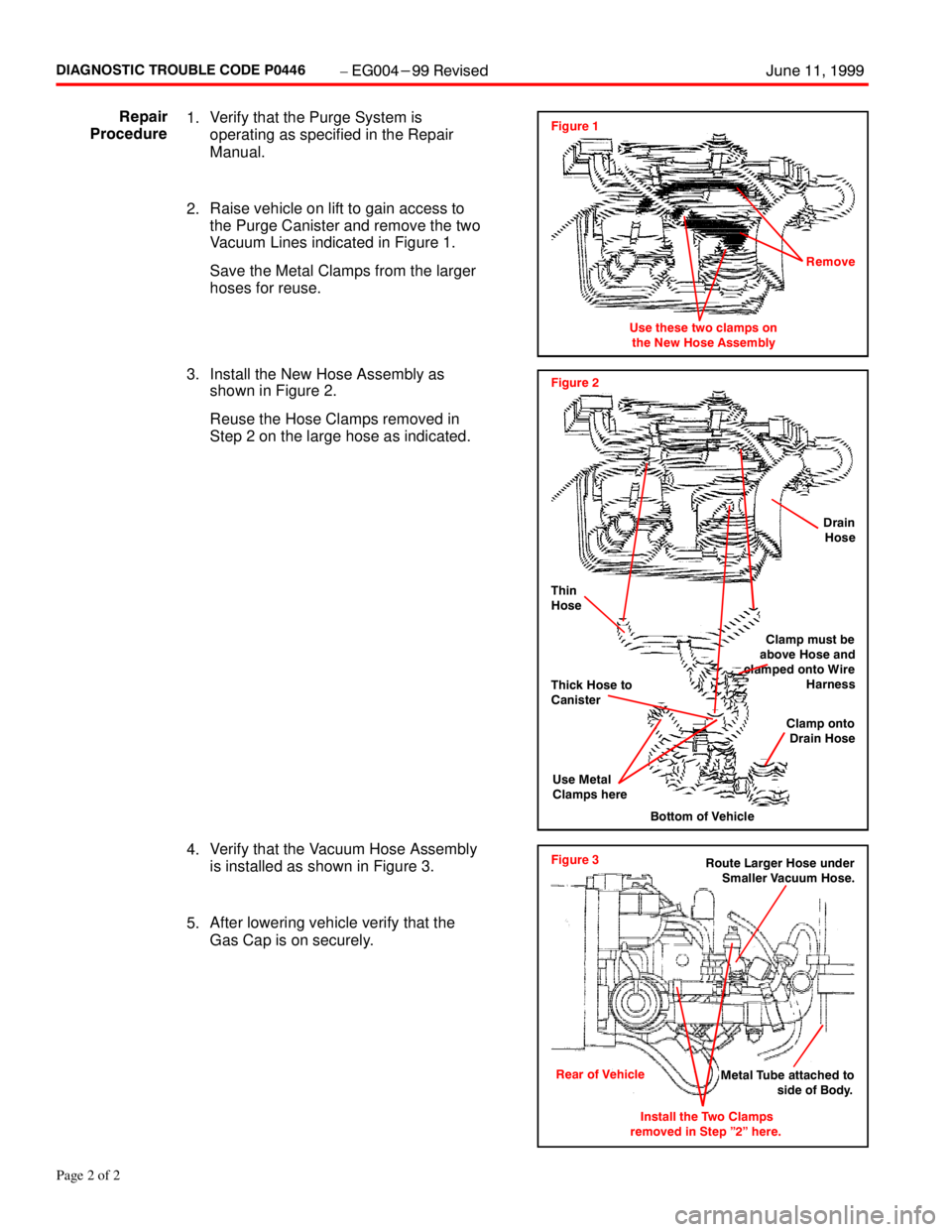
Procedure1.Verify that the Purge System is
operating as specified in the Repair
Manual.
2.Raise vehicle on lift to gain access to
the Purge Canister and remove the two
Vacuum Lines indicated in Figure 1.
Save the Metal Clamps from the larger
hoses for reuse.
4.Verify that the Vacuum Hose Assembly
is installed as shown in Figure 3.
5.After lowering vehicle verify that the
Gas Cap is on securely.
Figure 3
Rear of Vehicle
Install the Two Clamps
removed in Step "2" here.Route Larger Hose under
Smaller Vacuum Hose.
Metal Tube attached to
side of Body.
3.Install the New Hose Assembly as
shown in Figure 2.
Reuse the Hose Clamps removed in
Step 2 on the large hose as indicated.Figure 2
Bottom of Vehicle
Drain
Hose
Thin
Hose
Clamp onto
Drain Hose Clamp must be
above Hose and
clamped onto Wire
Harness
Thick Hose to
Canister
Use Metal
Clamps here
Figure 1
Use these two clamps on
the New Hose AssemblyRemove
Page 4578 of 4770
M.I.L. ªONº P0440, P0441 & P0446 ± EG013-02July 12, 2002
Page 4 of 5
8. Using a DVOM test at Pin 2 to a known good ground. The ECM provides ground
when the VSV is switched ON. (White and red wire on Solara, violet wire on Camry).
Is there continuity to ground at Pin 2 of the Vapor Pressure Sensor VSV connector
when the TANK BYPASS VSV ACTIVE TEST is switched to ON?
YES�Replace the Vapor Pressure Sensor VSV.
NO�Perform diagnosis of ground circuit.
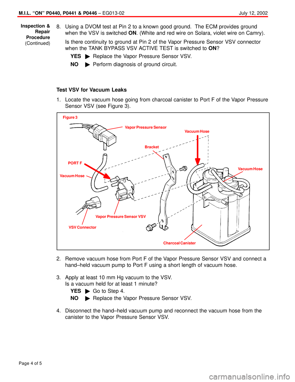
Test VSV for Vacuum Leaks
1. Locate the vacuum hose going from charcoal canister to Port F of the Vapor Pressure
Sensor VSV (see Figure 3).
Vapor Pressure Sensor
Figure 3
Bracket
Vacuum HoseVacuum Hose
Vapor Pressure Sensor VSV
VSV ConnectorVacuum Hose
PORT F
Charcoal Canister
2. Remove vacuum hose from Port F of the Vapor Pressure Sensor VSV and connect a
hand±held vacuum pump to Port F using a short length of vacuum hose.
3. Apply at least 10 mm Hg vacuum to the VSV.
Is a vacuum held for at least 1 minute?
YES�Go to Step 4.
NO�Replace the Vapor Pressure Sensor VSV.
4. Disconnect the hand±held vacuum pump and reconnect the vacuum hose from the
canister to the Vapor Pressure Sensor VSV.
Inspection &
Repair
Procedure
(Continued)
Page 4579 of 4770
M.I.L. ªONº P0440, P0441 & P0446 ± EG013-02July 12, 2002
Page 5 of 5
5. Locate the vacuum hose going from charcoal canister to Port P of the Vapor Pressure
Sensor VSV (see Figure 4).
Vapor Pressure Sensor
Figure 4
Bracket
Vacuum HoseVacuum Hose
Charcoal Canister Vapor Pressure Sensor VSV
VSV ConnectorVacuum Hose
PORT P
HOSE TO
REMOVE
6. Remove the vacuum hose from Port P of the Vapor Pressure Sensor VSV and
connect a hand±held vacuum pump to Port P using a short length of vacuum hose.
7. Apply at least 10 mm Hg vacuum to the VSV.
Is a vacuum held for at least 1 minute?
YES�Go to Step 8.
NO�Replace the Vapor Pressure Sensor VSV.
8. Disconnect the hand±held vacuum pump and reconnect the vacuum hose from the
canister to the Vapor Pressure Sensor VSV.
9. Continue diagnosis of the EVAP system.
Reference TSB EG005±01, ªEVAP System Operation Information.º
Inspection &
Repair
Procedure
(Continued)