Page 4076 of 4770
SF0DZ±03
B06348
VSV Connector for EGR
Vacuum Hose
VSV for EGR
SF±42
± SFI (5S±FE)VSV FOR EXHAUST GAS RECIRCULATION (EGR)
1475 Author�: Date�:
VSV FOR EXHAUST GAS RECIRCULATION (EGR)
COMPONENTS
Page 4080 of 4770
SF0E3±03
B06550
VSV for Vapor Pressure
Sensor Connector
VSV for Vapor
Pressure Sensor
Vacuum Hose
Charcoal Canister
SF±46
± SFI (5S±FE)VSV FOR VAPOR PRESSURE SENSOR
1479 Author�: Date�:
VSV FOR VAPOR PRESSURE SENSOR
COMPONENTS
Page 4086 of 4770
SF0E9±03
B00528
MAP Sensor
Vacuum Hose
MAP Sensor
Connector
MAP Sensor and Bracket Assembly
Wire Clamp
SF±52
± SFI (5S±FE)MANIFOLD ABSOLUTE PRESSURE (MAP) SENSOR
1485 Author�: Date�:
MANIFOLD ABSOLUTE PRESSURE (MAP) SENSOR
COMPONENTS
Page 4087 of 4770

SF0EA±03
S05545
DisconnectOhmmeter
E2
VC
A03009B01912
w/o Immobilizer
w/ ImmobiliserDisconnect
Vacuum
PIM
E2 ECM
ECM PIM (+)E2 (±) Voltmeter
Voltage Drop:
Applied
Vacuum
kPa
mmHg
in.Hg
Vo l t a ge
drop V13.3
100
3.94
0.3 ± 0.5
26.7 40.0 53.5 66.7
200
7.87
300
11.81400
15.75500
19.69
0.7 ± 0.9 1.1 ± 1.3 1.5 ± 1.7 1.9 ± 2.1
± SFI (5S±FE)MANIFOLD ABSOLUTE PRESSURE (MAP) SENSOR
SF±53
1486 Author�: Date�:
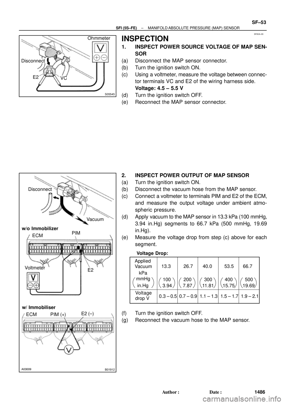
INSPECTION
1. INSPECT POWER SOURCE VOLTAGE OF MAP SEN-
SOR
(a) Disconnect the MAP sensor connector.
(b) Turn the ignition switch ON.
(c) Using a voltmeter, measure the voltage between connec-
tor terminals VC and E2 of the wiring harness side.
Voltage: 4.5 ± 5.5 V
(d) Turn the ignition switch OFF.
(e) Reconnect the MAP sensor connector.
2. INSPECT POWER OUTPUT OF MAP SENSOR
(a) Turn the ignition switch ON.
(b) Disconnect the vacuum hose from the MAP sensor.
(c) Connect a voltmeter to terminals PIM and E2 of the ECM,
and measure the output voltage under ambient atmo-
spheric pressure.
(d) Apply vacuum to the MAP sensor in 13.3 kPa (100 mmHg,
3.94 in.Hg) segments to 66.7 kPa (500 mmHg, 19.69
in.Hg).
(e) Measure the voltage drop from step (c) above for each
segment.
(f) Turn the ignition switch OFF.
(g) Reconnect the vacuum hose to the MAP sensor.
Page 4088 of 4770
SF0EF±04
B06554
Charcoal Canister Vapor Pressure Sensor
(Type A)Vapor Pressure Sensor
(Type B)
Vapor Pressure Sensor
Connector
Vacuum hose
SF±54
± SFI (5S±FE)VAPOR PRESSURE SENSOR
1487 Author�: Date�:
VAPOR PRESSURE SENSOR
COMPONENTS
Page 4089 of 4770

SF0EG±03
B06551
Disconnect
VC
E2Voltmeter
A03018S05603B06553B06552
B06570
Vacuum
Disconnect
ECME2
Disconnect
Pressure
Vacuum
PTNK
Voltmeter
PTNK (+) E2 (±) w/ Immobiliser
ECM
w/o Immobiliser
Pressure
Type A
Type B
P
± SFI (5S±FE)VAPOR PRESSURE SENSOR
SF±55
1488 Author�: Date�:
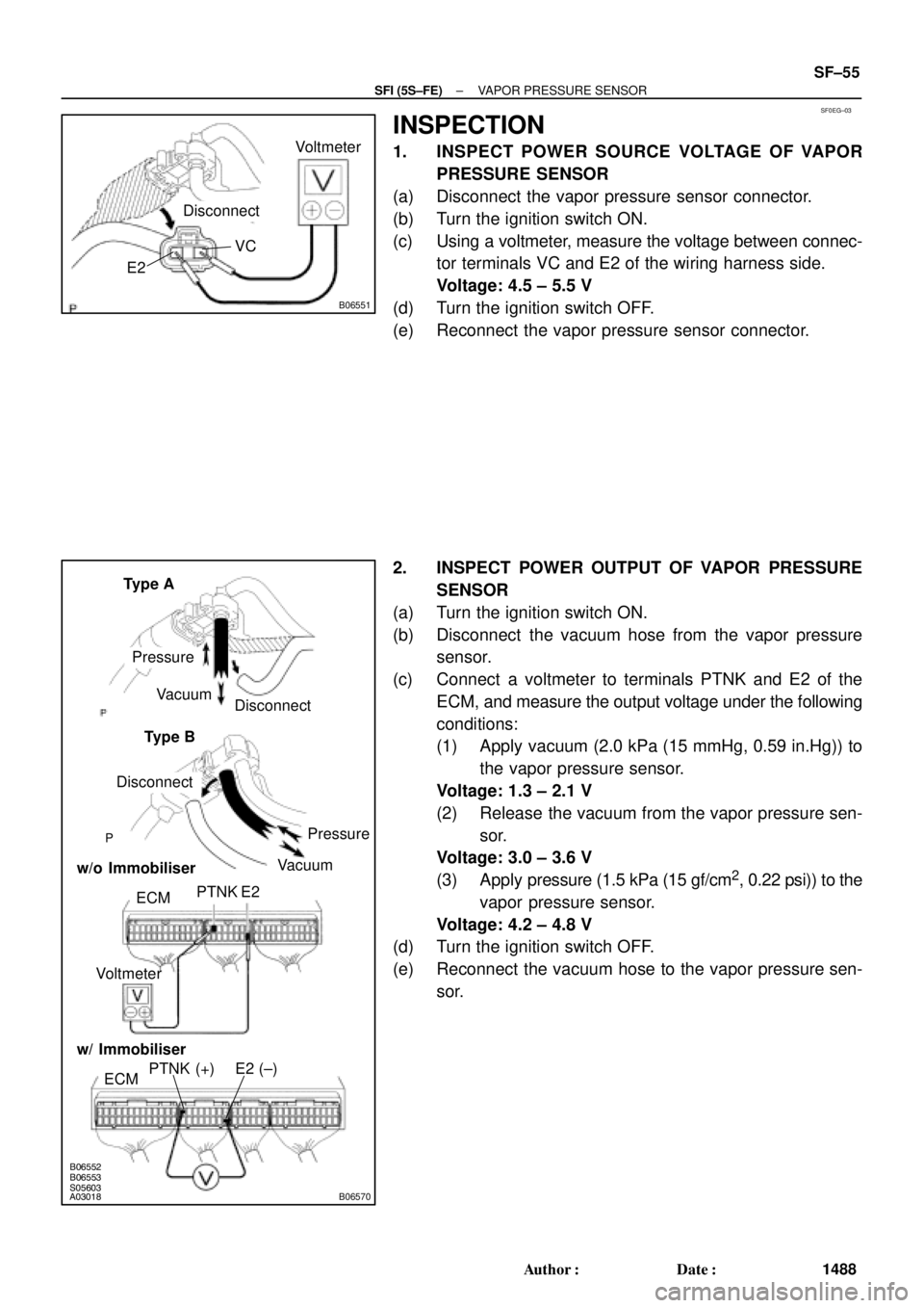
INSPECTION
1. INSPECT POWER SOURCE VOLTAGE OF VAPOR
PRESSURE SENSOR
(a) Disconnect the vapor pressure sensor connector.
(b) Turn the ignition switch ON.
(c) Using a voltmeter, measure the voltage between connec-
tor terminals VC and E2 of the wiring harness side.
Voltage: 4.5 ± 5.5 V
(d) Turn the ignition switch OFF.
(e) Reconnect the vapor pressure sensor connector.
2. INSPECT POWER OUTPUT OF VAPOR PRESSURE
SENSOR
(a) Turn the ignition switch ON.
(b) Disconnect the vacuum hose from the vapor pressure
sensor.
(c) Connect a voltmeter to terminals PTNK and E2 of the
ECM, and measure the output voltage under the following
conditions:
(1) Apply vacuum (2.0 kPa (15 mmHg, 0.59 in.Hg)) to
the vapor pressure sensor.
Voltage: 1.3 ± 2.1 V
(2) Release the vacuum from the vapor pressure sen-
sor.
Voltage: 3.0 ± 3.6 V
(3) Apply pressure (1.5 kPa (15 gf/cm
2, 0.22 psi)) to the
vapor pressure sensor.
Voltage: 4.2 ± 4.8 V
(d) Turn the ignition switch OFF.
(e) Reconnect the vacuum hose to the vapor pressure sen-
sor.
Page 4122 of 4770
SF07J±03
B06391
Air Intake Chamber Stay
No.1 Engine Hanger
VSV Connector for
EVAP
Ground Cable
Ground Strap
Air Intake Chamber
AssemblyNo.2 EGR
Pipe
VSV Connector
for EGR
Engine Wire
PCV Hose
VSV Connector for ACIS
Spacer
Injector Injector Connector
High±Tension Cord Set PS Pressure Tube
California A/T
Brake Booster
Vacuum Hose
Throttle Position
Sensor Connector
EGR Valve Position
Sensor Connector
IAC Valve
Connector
V±Bank Cover
Accelerator Cable
Throttle Cable
Air Cleaner Hose
EGR Gas Temperature
Sensor Connector Purge Hose
Vacuum
Hose
Water Bypass Hose
Air Assist Hose and Pipe � Gasket
� O±Ring
� O±Ring � Grommet
Injector� Insulator
� Retainer
� Gasket
� Gasket
19.5 (200, 14)
39 (400, 29)
12 (120, 9)
43 (440, 32)
10 (100, 7)19.5 (200, 14)
N´m (kgf´cm, ft´lbf) : Specified torque
� Non±reusable part
DLC1
SF±22
± SFI (1MZ±FE)INJECTOR
1521 Author�: Date�:
COMPONENTS
Page 4137 of 4770

S04593
SF07T±03
S04536
Vacuum
VTAOhmmeter
E2
VC
S04604
Plug
Disconnect
± SFI (1MZ±FE)THROTTLE BODY
SF±37
1536 Author�: Date�:
THROTTLE BODY
ON±VEHICLE INSPECTION
1. INSPECT THROTTLE BODY
Check that the throttle linkage moves smoothly.
2. INSPECT THROTTLE POSITION SENSOR
(a) Disconnect the sensor connector.
(b) Disconnect the vacuum hose from the throttle body.
(c) Apply vacuum to the throttle opener.
(d) Using an ohmmeter, measure the resistance between
each terminal.
Resistance:
Throttle valve
conditionBetween
terminalsResistance
Fully closedVTA ± E20.2 ± 6.3 kW
Fully openVTA ± E22.0 ± 10.2 kW
±VC ± E22.5 ± 5.9 kW
(e) Reconnect the vacuum hose to the throttle body.
(f) Reconnect the sensor connector.
3. INSPECT THROTTLE OPENER
(a) Allow the engine to warm up to normal operating tempera-
ture.
(b) Check idle speed.
Idle speed: 700 ± 50 rpm
(c) Disconnect the vacuum hose from the throttle opener,
and plug the hose end.
(d) Check the throttle opener setting speed.
Throttle opener setting speed: 900 ± 1,950 rpm
If the throttle opener setting is not as specified, replace the
throttle body.
(e) Stop the engine.
(f) Reconnect the vacuum hose to the throttle opener.
(g) Start the engine and check that the idle speed returns to
the correct speed.