Page 4148 of 4770
S05036
Vacuum Gage
SF083±03
S05037
Approx.
27.6 kPa SF±48
± SFI (1MZ±FE)ACOUSTIC CONTROL INDUCTION SYSTEM (ACIS)
1547 Author�: Date�:
ACOUSTIC CONTROL INDUCTION
SYSTEM (ACIS)
ON±VEHICLE INSPECTION
INSPECT INTAKE AIR CONTROL VALVE
(a) Using a 3±way connector, connect vacuum gauge to the
actuator hose.
(b) Start the engine.
(c) While the engine is idling, check that the vacuum gauge
needle does not move.
(d) Rapidly depress the accelerator pedal to fully open posi-
tion and check that the vacuum gauge needle momentari-
ly fluctuates up to approx. 26.7 kPa (200 mmHg, 7.9
in.Hg). (The actuator rod is pulled out.)
Page 4149 of 4770
SF084±03
B06467
Intake Air Control Valve� Gasket
Actuator Vacuum Hose
Ground Strap
Ground Cable
: Specified torque
� Non±reusable part
14.5 (145, 10)
N´m (kgf´cm, ft´lbf)
DLC1 Bracket
DLC1
± SFI (1MZ±FE)ACOUSTIC CONTROL INDUCTION SYSTEM (ACIS)
SF±49
1548 Author�: Date�:
COMPONENTS
Page 4150 of 4770
SF085±02
B06470
(1) (2)
B06471
SF±50
± SFI (1MZ±FE)ACOUSTIC CONTROL INDUCTION SYSTEM (ACIS)
1549 Author�: Date�:
REMOVAL
1. DISCONNECT ACTUATOR VACUUM HOSE
2. DISCONNECT DLC1 FROM DLC1 BRACKET
3. REMOVE INTAKE AIR CONTROL VALVE
(a) Remove the 4 nuts and DLC1 bracket, and disconnect the
ground strap and cable.
(b) Remove the intake air control valve by prying a screwdriv-
er between the intake air control valve and air intake
chamber.
(c) Remove the gasket.
Page 4152 of 4770
SF087±03
B06468
New Gasket
S05052
Seal
Packing
Rubber Seal
Packing SF±52
± SFI (1MZ±FE)ACOUSTIC CONTROL INDUCTION SYSTEM (ACIS)
1551 Author�: Date�:
INSTALLATION
1. INSTALL INTAKE AIR CONTROL VALVE
(a) Install a new gasket to the air intake chamber.
(b) Apply a light coat of engine oil to the rubber portions.
(c) Apply seal packing to the positions of the intake air control
valve shown in the illustration.
Seal packing: Part No. 08826±00080 or equivalent
(d) Install the intake air control valve, DLC1 bracket, ground
strap and cable with the 4 nuts.
Torque: 14.5 N´m (145 kgf´cm, 10 ft´lbf)
2. CONNECT DLC1
3. CONNECT ACTUATOR VACUUM HOSE
Page 4155 of 4770
SF08A±03
S04762
V±Bank Cover
High±Tension Cord CoverEmission Control Valve Set
VSV Connector for EVAPVSV for EGRVacuum Hose
VSV Connector for EGR
VSV Connector for ACIS
± SFI (1MZ±FE)VSV FOR EXHAUST GAS RECIRCULATION (EGR)
SF±55
1554 Author�: Date�:
VSV FOR EXHAUST GAS RECIRCULATION (EGR)
COMPONENTS
Page 4156 of 4770

SF08B±03
S04514
Ohmmeter
Continuity
S04513
Ohmmeter
No Continuity
S04515
Air
E
G
S04512
Air
Battery SF±56
± SFI (1MZ±FE)VSV FOR EXHAUST GAS RECIRCULATION (EGR)
1555 Author�: Date�:
INSPECTION
1. REMOVE V±BANK COVER, HIGH±TENSION CORD
COVER AND EMISSION CONTROL VALVE SET
2. REMOVE VSV
(a) Disconnect the 3 vacuum hoses from the VSV.
(b) Remove the screw and VSV.
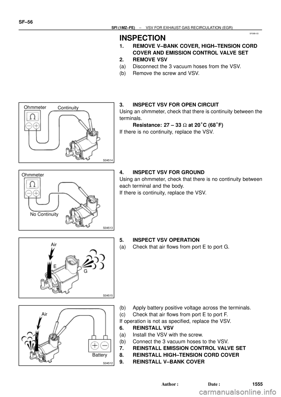
3. INSPECT VSV FOR OPEN CIRCUIT
Using an ohmmeter, check that there is continuity between the
terminals.
Resistance: 27 ± 33 W at 20°C (68°F)
If there is no continuity, replace the VSV.
4. INSPECT VSV FOR GROUND
Using an ohmmeter, check that there is no continuity between
each terminal and the body.
If there is continuity, replace the VSV.
5. INSPECT VSV OPERATION
(a) Check that air flows from port E to port G.
(b) Apply battery positive voltage across the terminals.
(c) Check that air flows from port E to port F.
If operation is not as specified, replace the VSV.
6. REINSTALL VSV
(a) Install the VSV with the screw.
(b) Connect the 3 vacuum hoses to the VSV.
7. REINSTALL EMISSION CONTROL VALVE SET
8. REINSTALL HIGH±TENSION CORD COVER
9. REINSTALL V±BANK COVER
Page 4159 of 4770
SF08E±03
S04760
High±Tension Cord Cover
VSV Connector for ACIS
Vacuum Hose
VSV for ACISVSV Connector for EVAP
VSV Connector for EGR Emission Control Valve Set
± SFI (1MZ±FE)VSV FOR ACOUSTIC CONTROL INDUCTION
SYSTEM (ACIS)SF±59
1558 Author�: Date�:
VSV FOR ACOUSTIC CONTROL INDUCTION SYSTEM (ACIS)
COMPONENTS
Page 4160 of 4770

SF08F±04
S04525
Continuity Ohmmeter
S04524
No Continuity Ohmmeter
FI6393
Air
E
Filter
S04523
Air
E
F
Battery SF±60
± SFI (1MZ±FE)VSV FOR ACOUSTIC CONTROL INDUCTION
SYSTEM (ACIS)
1559 Author�: Date�:
INSPECTION
1. REMOVE V±BANK COVER, HIGH±TENSION CORD
COVER AND EMISSION CONTROL VALVE SET
2. REMOVE VSV
(a) Disconnect the 2 vacuum hoses from the VSV.
(b) Remove the screw and VSV.
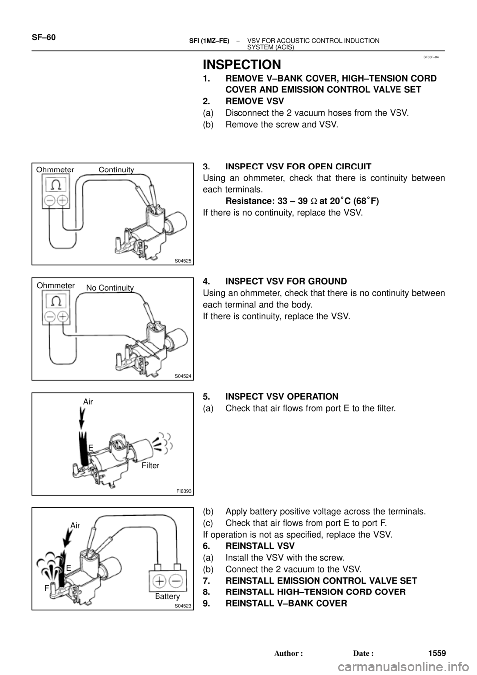
3. INSPECT VSV FOR OPEN CIRCUIT
Using an ohmmeter, check that there is continuity between
each terminals.
Resistance: 33 ± 39 W at 20°C (68°F)
If there is no continuity, replace the VSV.
4. INSPECT VSV FOR GROUND
Using an ohmmeter, check that there is no continuity between
each terminal and the body.
If there is continuity, replace the VSV.
5. INSPECT VSV OPERATION
(a) Check that air flows from port E to the filter.
(b) Apply battery positive voltage across the terminals.
(c) Check that air flows from port E to port F.
If operation is not as specified, replace the VSV.
6. REINSTALL VSV
(a) Install the VSV with the screw.
(b) Connect the 2 vacuum to the VSV.
7. REINSTALL EMISSION CONTROL VALVE SET
8. REINSTALL HIGH±TENSION CORD COVER
9. REINSTALL V±BANK COVER