Page 2743 of 4770
BE6653
S00558 S00557A00474
ON
Air
E Air
E
F
F GG VSV is OFF VSV is ON
± DIAGNOSTICSENGINE (1MZ±FE)
DI±323
558 Author�: Date�:
10 Check VSV for vapor pressure sensor.
PREPARATION:
(a) Connect the TOYOTA hand±held tester to the DLC3.
(b) Turn the ignition switch ON and push the OBD II scan tool
or TOYOTA hand±held tester main switch ON.
(c) Select the ACTIVE TEST mode on the TOYOTA hand±
held tester.
CHECK:
Check the VSV operation when it is operated by TOYOTA
hand±held tester.
OK:
VSV is ON:
Air from pipe E is flowing out through pipe F.
VSV is OFF:
Air from pipe E is flowing out through pipe G.
OK Go to step 13.
NG
11 Check operation of VSV for vapor pressure sensor (See page SF±62).
OK Go to step 12.
NG
Replace VSV and charcoal canister, and then clean the vacuum hoses between charcoal canister
and VSV for vapor pressure sensor, and VSV for vapor pressure sensor and vapor pressure sen-
sor.
Page 2745 of 4770

A07147
E2 (±) PTNK (+)
EngineStart
Stop
OFF ON OFF VSV for
ON
Vapor
Pressure
Sensor
VSV for
EVAP
5 sec.
Measure Voltage
± DIAGNOSTICSENGINE (1MZ±FE)
DI±325
560 Author�: Date�:
14 Check vacuum hoses between charcoal canister and VSV for vapor pressure
sensor, and vapor pressure sensor and VSV for vapor pressure sensor.
CHECK:
(a) Check that the vacuum hose is connected correctly.
(b) Check the vacuum hose for looseness and disconnection.
(c) Check the vacuum hose for cracks, hole, damage and blockage.
NG Repair or replace.
OK
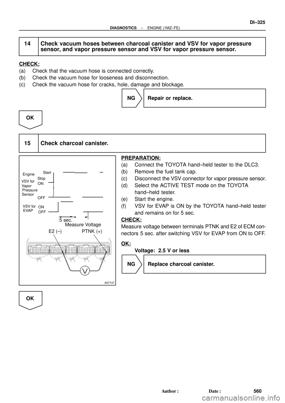
15 Check charcoal canister.
PREPARATION:
(a) Connect the TOYOTA hand±held tester to the DLC3.
(b) Remove the fuel tank cap.
(c) Disconnect the VSV connector for vapor pressure sensor.
(d) Select the ACTIVE TEST mode on the TOYOTA
hand±held tester.
(e) Start the engine.
(f) VSV for EVAP is ON by the TOYOTA hand±held tester
and remains on for 5 sec.
CHECK:
Measure voltage between terminals PTNK and E2 of ECM con-
nectors 5 sec. after switching VSV for EVAP from ON to OFF.
OK:
Voltage: 2.5 V or less
NG Replace charcoal canister.
OK
Page 2746 of 4770
DI±326
± DIAGNOSTICSENGINE (1MZ±FE)
561 Author�: Date�:
16 Remove charcoal canister and check it (See page EC±6).
NG Replace charcoal canister.
OK
17 Check fuel tank over fill check valve (See page EC±2).
NG Replace fuel tank over fill check valve or fuel
tank.
OK
Check and replace ECM (See page IN±31).
OBD II scan tool (excluding TOYOTA hand±held tester)
1 Check VSV connector for EVAP, VSV connector for vapor pressure sensor and
vapor pressure sensor connector for looseness and disconnection.
NG Repair or connect VSV or sensor connector.
OK
2 Check vacuum hoses (1), (4), (5), (6) (7) and (8) on Page DI±311).
CHECK:
(a) Check that the vacuum hose is connected correctly.
(b) Check the vacuum hose for looseness and disconnection.
(c) Check the vacuum hose for cracks, hole, damage and blockage.
NG Repair or replace.
OK
Page 2748 of 4770
A07148
ON
EVA1
ON OFF
VSV is ON VSV is OFF
E
FAir Air
E
F
DI±328
± DIAGNOSTICSENGINE (1MZ±FE)
563 Author�: Date�:
6 Check VSV for EVAP.
PREPARATION:
(a) Remove the glove compartment (See page SF±73).
(b) Turn the ignition switch ON.
CHECK:
Check VSV function.
(1) Connect between terminal EVA1 of the ECM
connector and body ground (ON).
(2) Disconnect between terminal EVP of the ECM con-
nector and body ground (OFF).
OK:
(1) VSV is ON:
Air from pipe E is flowing out through pipe F.
(2) VSV is OFF:
Air does not flow from pipe E to pipe F.
OK Go to step 9.
NG
7 Check operation of VSV for EVAP (See page SF±58).
OK Go to step 9.
NG
Replace VSV and charcoal canister, and then clean the vacuum hoses between throttle body and
VSV for EVAP, and VSV for EVAP and charcoal canister.
Page 2750 of 4770
DI±330
± DIAGNOSTICSENGINE (1MZ±FE)
565 Author�: Date�:
10 Check operation of VSV for vapor pressure sensor (See page SF±62).
OK Go to step 11.
NG
Replace VSV and clean the vacuum hoses between charcoal canister and VSV for vapor pressure
sensor, and VSV for vapor pressure sensor and vapor pressure sensor, and then check the char-
coal canister.
11 Check for open and short in harness and connector between EFI main relay
(Marking: EFI) and VSV for vapor pressure sensor, and VSV for vapor pressure
sensor and ECM (See page IN±31).
NG Repair or replace harness or connector.
OK
Check and replace ECM (See page IN±31).
12 Check the fuel tank over fill check valve (See page EC±6).
NG Replace fuel tank over fill check valve or fuel
tank.
OK
Check and replace charcoal canister
(See page EC±6).
Page 2779 of 4770

A00379
ON
1 (+)
BE6653S05694
S05742
1
2
± DIAGNOSTICSENGINE (1MZ±FE)
DI±359
594 Author�: Date�:
INSPECTION PROCEDURE
HINT:
�If DTCs ºP0110º (Intake Air Temp. Circuit Malfunction), ºP0115º (Engine Coolant Temp. Circuit Mal-
function), ºP0120º (Throttle/Pedal Position/Switch ºAº Circuit Malfunction), ºP1410º (EGR Valve Posi-
tion Sensor Circuit Malfunction) are output simultaneously, E2 (Sensor Ground) may be open.
�Read freeze frame data using TOYOTA hand±held tester or OBD II scan tool. Because freeze frame
records the engine conditions when the malfunction is detected, when troubleshooting it is useful for
determining whether the vehicle was running or stopped, the engine warmed up or not, the air±fuel
ratio lean or rich, etc. at the time of the malfunction.
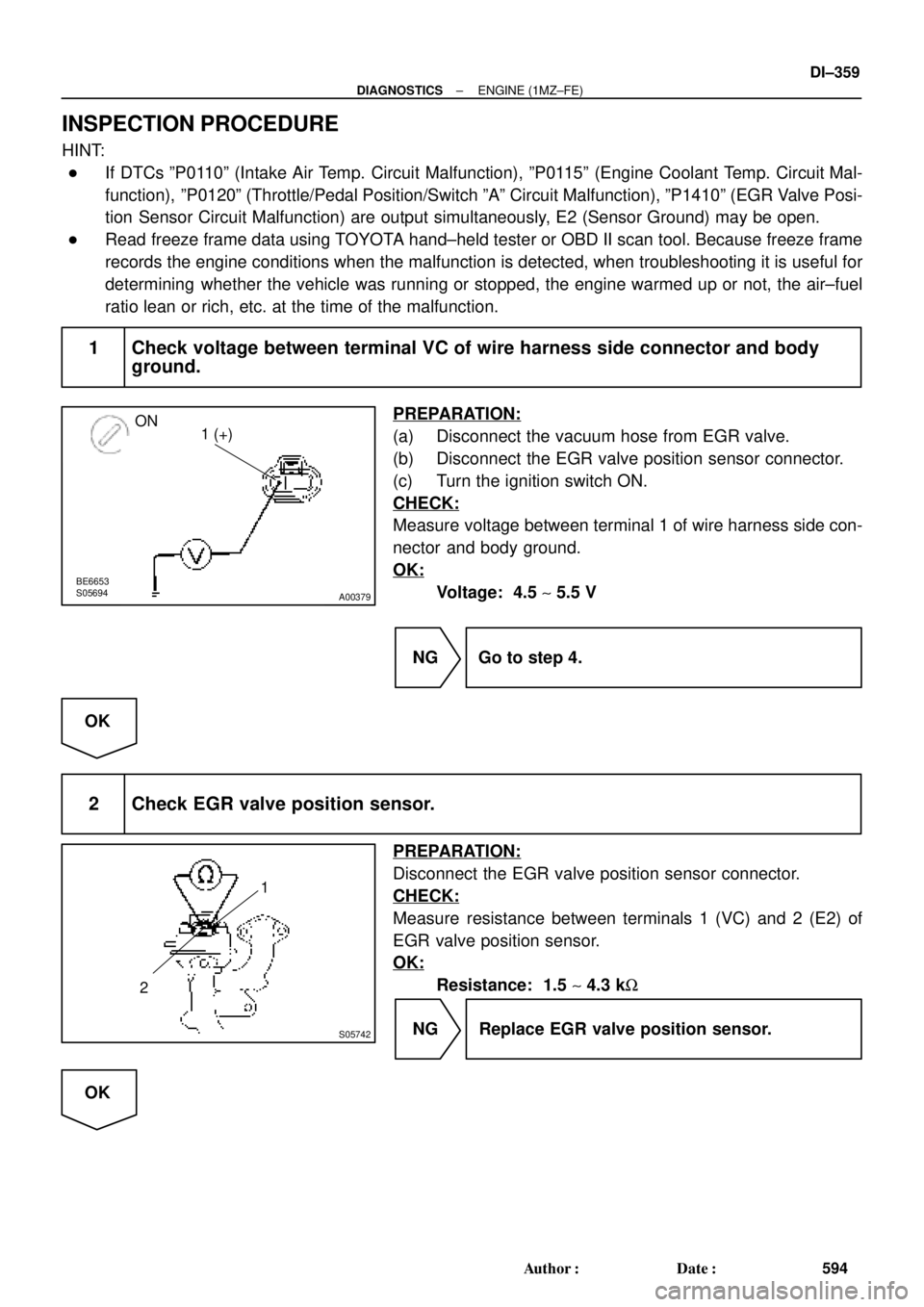
1 Check voltage between terminal VC of wire harness side connector and body
ground.
PREPARATION:
(a) Disconnect the vacuum hose from EGR valve.
(b) Disconnect the EGR valve position sensor connector.
(c) Turn the ignition switch ON.
CHECK:
Measure voltage between terminal 1 of wire harness side con-
nector and body ground.
OK:
Voltage: 4.5 ~ 5.5 V
NG Go to step 4.
OK
2 Check EGR valve position sensor.
PREPARATION:
Disconnect the EGR valve position sensor connector.
CHECK:
Measure resistance between terminals 1 (VC) and 2 (E2) of
EGR valve position sensor.
OK:
Resistance: 1.5 ~ 4.3 kW
NG Replace EGR valve position sensor.
OK
Page 2780 of 4770
A02036
ON
EGLS (+) E2 (±)
DI±360
± DIAGNOSTICSENGINE (1MZ±FE)
595 Author�: Date�:
3 Check voltage between terminals EGLS and E2 of ECM connectors.
PREPARATION:
(a) Disconnect the vacuum hose from EGR valve.
(b) Connect the hand±held vacuum pump to EGR valve.
(c) Remove the glove compartment (See page SF±73).
(d) Turn the ignition switch ON.
CHECK:
Measure voltage between terminals EGLS and E2 of the ECM
connectors.
OK:
ConditionVltEGR valveVacuumVoltage
Fully closed0 kPa
(0 mmHg, 0 in.Hg)0.4 ~ 1.6 V
Fully open17.3 kPa
(130 mmHg, 5.12 in.Hg)3.2 ~ 5.1 V
NG Check for open and short in harness and
connector between ECM and EGR valve
position sensor (EGLS or E2 line).
OK
Check and replace ECM (See page IN±31).
Page 3359 of 4770
EC03A±03
B06542
PCV Valve
VSV for EGR
Front TWC
(California)EGR Vacuum Modulator
EGR Valve
TWC (Except California)
Rear TWC (California)
VSV for EVAP
Vent Line
Charcoal Canister
Fuel Tank
EVAP Line
Air Drain Hose
Filler Pipe
Air Inlet LinePurge Line Cutoff Valve
Fill Check Valve
EVAP Service Port
Fuel Tank Cap
VSV for Vapor
Pressure Sensor Vapor Pressure Sensor
EC±2
± EMISSION CONTROL (5S±FE)PARTS LAYOUT AND SCHEMATIC DRAWING
1400 Author�: Date�:
PARTS LAYOUT AND SCHEMATIC DRAWING
LOCATION