Page 3360 of 4770
EC03B±03
B06549
VSV for EGR Front TWC
(California)EGR Vacuum Modulator
EGR
Valve
TWC (Except California)
Rear TWC (California)VSV
for EVAP
Vent Line
Charcoal CanisterFuel Tank EVAP Line
Air Drain HoseFiller Pipe
Air Inlet Line Purge LineEVAP Service Port
Fuel Tank Cap
Vapor
Pressure
SensorVSV for Vapor
Pressure Sensor
± EMISSION CONTROL (5S±FE)PARTS LAYOUT AND SCHEMATIC DRAWING
EC±3
1401 Author�: Date�:
DRAWING
Page 3364 of 4770

B06548Battery
B06545
B06543
Hose Clipper
Air Drain Hose
± EMISSION CONTROL (5S±FE)EVAPORATIVE EMISSION (EVAP) CONTROL SYSTEM
EC±7
1405 Author�: Date�:
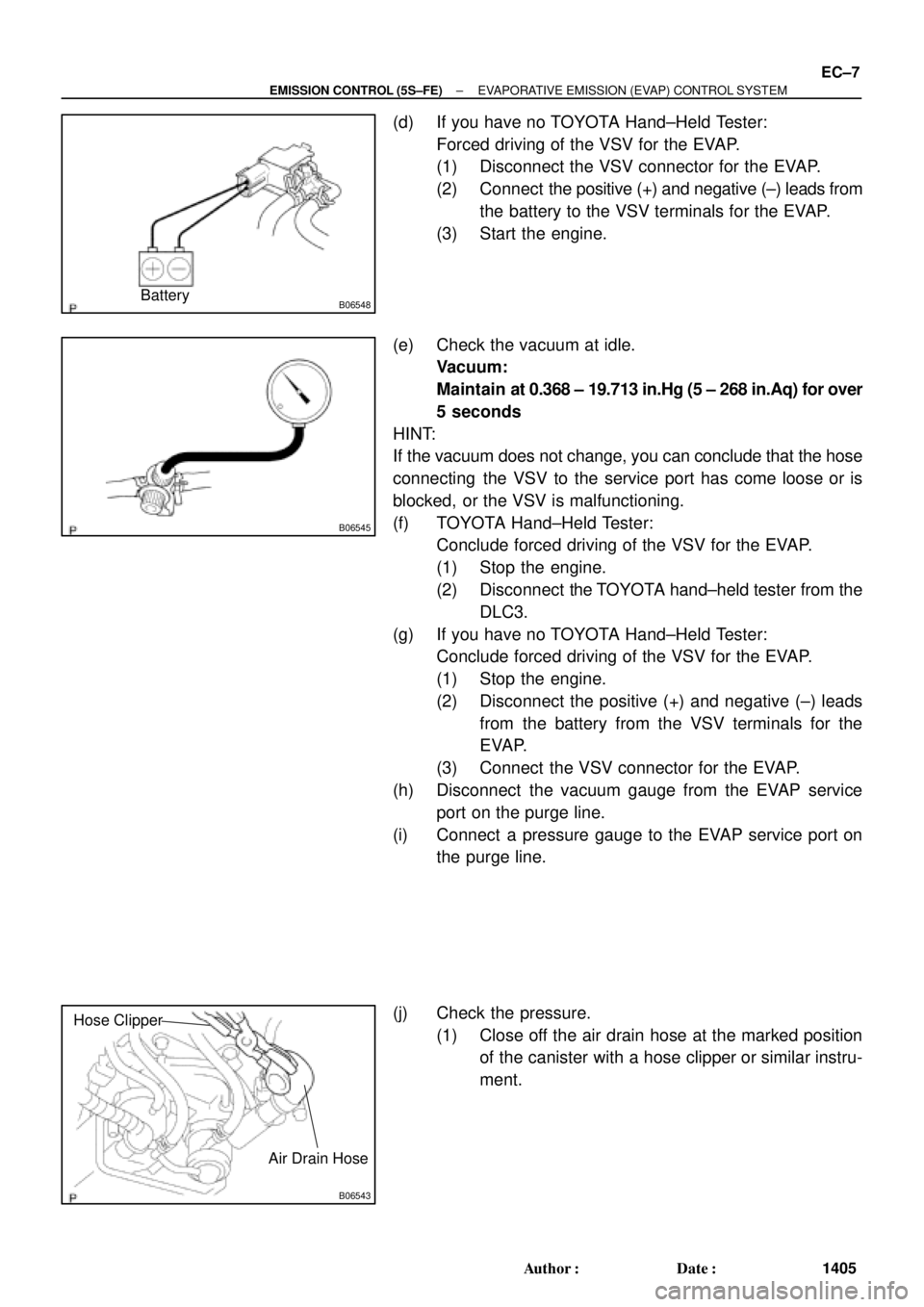
(d) If you have no TOYOTA Hand±Held Tester:
Forced driving of the VSV for the EVAP.
(1) Disconnect the VSV connector for the EVAP.
(2) Connect the positive (+) and negative (±) leads from
the battery to the VSV terminals for the EVAP.
(3) Start the engine.
(e) Check the vacuum at idle.
Vacuum:
Maintain at 0.368 ± 19.713 in.Hg (5 ± 268 in.Aq) for over
5 seconds
HINT:
If the vacuum does not change, you can conclude that the hose
connecting the VSV to the service port has come loose or is
blocked, or the VSV is malfunctioning.
(f) TOYOTA Hand±Held Tester:
Conclude forced driving of the VSV for the EVAP.
(1) Stop the engine.
(2) Disconnect the TOYOTA hand±held tester from the
DLC3.
(g) If you have no TOYOTA Hand±Held Tester:
Conclude forced driving of the VSV for the EVAP.
(1) Stop the engine.
(2) Disconnect the positive (+) and negative (±) leads
from the battery from the VSV terminals for the
EVAP.
(3) Connect the VSV connector for the EVAP.
(h) Disconnect the vacuum gauge from the EVAP service
port on the purge line.
(i) Connect a pressure gauge to the EVAP service port on
the purge line.
(j) Check the pressure.
(1) Close off the air drain hose at the marked position
of the canister with a hose clipper or similar instru-
ment.
Page 3368 of 4770
EC03F±03
S05556
EGR Valve
Vacuum HoseVacuum Hose
EGR Valve
� Gasket
� Non±reusable part� Gasket
± EMISSION CONTROL (5S±FE)EXHAUST GAS RECIRCULATION (EGR) SYSTEM
EC±11
1409 Author�: Date�:
EXHAUST GAS RECIRCULATION (EGR) SYSTEM
COMPONENTS
Page 3369 of 4770

EC03G±04
S05568
Cap
Filter
B06540
Vacuum Gauge
3±Way Connector
A07370
SST
E1
TE1
B06541
HOTHigh Vacuum at 2,500 rpm
Port R
Disconnect
EC±12
± EMISSION CONTROL (5S±FE)EXHAUST GAS RECIRCULATION (EGR) SYSTEM
1410 Author�: Date�:
INSPECTION
1. INSPECT EGR SYSTEM
(a) Inspect and clean the filter in the EGR vacuum modulator.
(1) Remove the cap and filter.
(2) Check the filter for contamination or damage.
(3) Using compressed air, clean the filter.
(4) Reinstall the filter and cap.
HINT:
Install the filter with the coarser surface facing the atmospheric
side (outward).
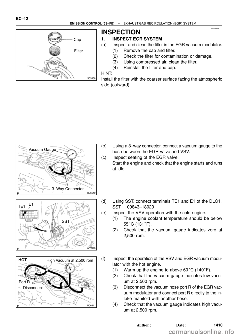
(b) Using a 3±way connector, connect a vacuum gauge to the
hose between the EGR valve and VSV.
(c) Inspect seating of the EGR valve.
Start the engine and check that the engine starts and runs
at idle.
(d) Using SST, connect terminals TE1 and E1 of the DLC1.
SST 09843±18020
(e) Inspect the VSV operation with the cold engine.
(1) The engine coolant temperature should be below
55°C (131°F).
(2) Check that the vacuum gauge indicates zero at
2,500 rpm.
(f) Inspect the operation of the VSV and EGR vacuum modu-
lator with the hot engine.
(1) Warm up the engine to above 60°C (140°F).
(2) Check that the vacuum gauge indicates low vacu-
um at 2,500 rpm.
(3) Disconnect the vacuum hose port R of the EGR vac-
uum modulator and connect port R directly to the in-
take manifold with another hose.
(4) Check that the vacuum gauge indicates high vacu-
um at 2,500 rpm.
Page 3370 of 4770

B06539
Disconnect
S05567
Air Engine Stopped
S05566
Engine at
2,500 rpm
Air
± EMISSION CONTROL (5S±FE)EXHAUST GAS RECIRCULATION (EGR) SYSTEM
EC±13
1411 Author�: Date�:
HINT:
As a large amount of exhaust gas enters, the engine will misfire
slightly.
(g) Remove the vacuum gauge, and reconnect the vacuum
hoses to the proper locations.
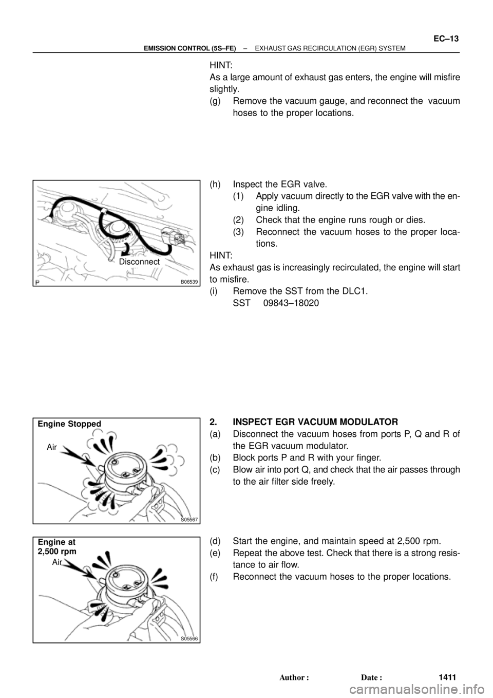
(h) Inspect the EGR valve.
(1) Apply vacuum directly to the EGR valve with the en-
gine idling.
(2) Check that the engine runs rough or dies.
(3) Reconnect the vacuum hoses to the proper loca-
tions.
HINT:
As exhaust gas is increasingly recirculated, the engine will start
to misfire.
(i) Remove the SST from the DLC1.
SST 09843±18020
2. INSPECT EGR VACUUM MODULATOR
(a) Disconnect the vacuum hoses from ports P, Q and R of
the EGR vacuum modulator.
(b) Block ports P and R with your finger.
(c) Blow air into port Q, and check that the air passes through
to the air filter side freely.
(d) Start the engine, and maintain speed at 2,500 rpm.
(e) Repeat the above test. Check that there is a strong resis-
tance to air flow.
(f) Reconnect the vacuum hoses to the proper locations.
Page 3371 of 4770
S05559
EC±14
± EMISSION CONTROL (5S±FE)EXHAUST GAS RECIRCULATION (EGR) SYSTEM
1412 Author�: Date�:
3. INSPECT EGR VALVE
(a) Remove the EGR valve.
(1) Disconnect the 2 vacuum hoses from the EGR
valve.
(2) Remove the 2 bolts, 2 nuts, EGR valve and 2 gas-
kets.
(b) Check the EGR valve for sticking and heavy carbon de-
posits.
If a problem is found, replace the valve.
(c) Reinstall the EGR valve.
(1) Temporarily 2 new gasket and the EGR valve with
the 2 nuts and 2 bolts.
(2) Tighten the nuts.
Torque: 13.3 N´m (136 kgf´cm, 10 ft´lbf)
(3) Tighten the bolts.
Torque: 10 N´m (102 kgf´cm, 7 ft´lbf)
(4) Connect the 2 vacuum hoses to the EGR valve.
4. INSPECT VSV FOR EGR (See page SF±43)
Page 3376 of 4770
EC01V±03
B06386
VSV for EGREGR Valve
Vent LineCharcoal Canister
Fuel Tank
EVAP Line
Air Drain Hose
Filler Pipe
Air Inlet Line
Purge Line
Cut Off Valve
Fill Check Valve
VSV for EVAP
VCVVacuum Surge Tank
EVAP Service Port
Vapor Pressure Sensor
Fuel Tank Cap
VSV for Vapor Pressure Sensor
Vacuum Surge Tank EC±2
± EMISSION CONTROL (1MZ±FE)PARTS LAYOUT AND SCHEMATIC DRAWING
1417 Author�: Date�:
PARTS LAYOUT AND SCHEMATIC DRAWING
LOCATION
Page 3377 of 4770
EC01W±03
B06721
VSV for Vapor
Pressure Sensor Vapor Pressure
SensorVacuum Surge
Tank
EGR Valve
Position
Sensor
A/F Sensor
(California A/T)
Heated Oxygen Sensor
(Bank 2 Sensor 1/
Except California A/T)
A/F Sensor
(California A/T)
Heated Oxygen
Sensor
(Bank 1 Sensor 1/
Except California A/T)
Heated Oxygen
Sensor
(Bank 1 Sensor 2) VCV
TWC VSV for EVAP
Fuel Tank
Charcoal
CanisterVSV for EGR
WU±TWC
(California A/T)
EVAP Service Port
Purge Line
Air Inlet Line
Air Drain Hose
WU±TWC
(California A/T)
EVAP Line
Vent Line
± EMISSION CONTROL (1MZ±FE)PARTS LAYOUT AND SCHEMATIC DRAWING
EC±3
1418 Author�: Date�:
DRAWING