Page 1782 of 4770
Q10066
AX±24
± AUTOMATIC TRANSAXLE (A140E)AUTOMATIC TRANSAXLE UNIT
1917 Author�: Date�:
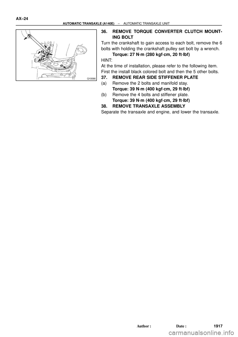
36. REMOVE TORQUE CONVERTER CLUTCH MOUNT-
ING BOLT
Turn the crankshaft to gain access to each bolt, remove the 6
bolts with holding the crankshaft pulley set bolt by a wrench.
Torque: 27 N´m (280 kgf´cm, 20 ft´lbf)
HINT:
At the time of installation, please refer to the following item.
First the install black colored bolt and then the 5 other bolts.
37. REMOVE REAR SIDE STIFFENER PLATE
(a) Remove the 2 bolts and manifold stay.
Torque: 39 N´m (400 kgf´cm, 29 ft´lbf)
(b) Remove the 4 bolts and stiffener plate.
Torque: 39 N´m (400 kgf´cm, 29 ft´lbf)
38. REMOVE TRANSAXLE ASSEMBLY
Separate the transaxle and engine, and lower the transaxle.
Page 1783 of 4770
AX03I±01
AT3412
± AUTOMATIC TRANSAXLE (A140E)AUTOMATIC TRANSAXLE UNIT
AX±25
1918 Author�: Date�:
INSTALLATION
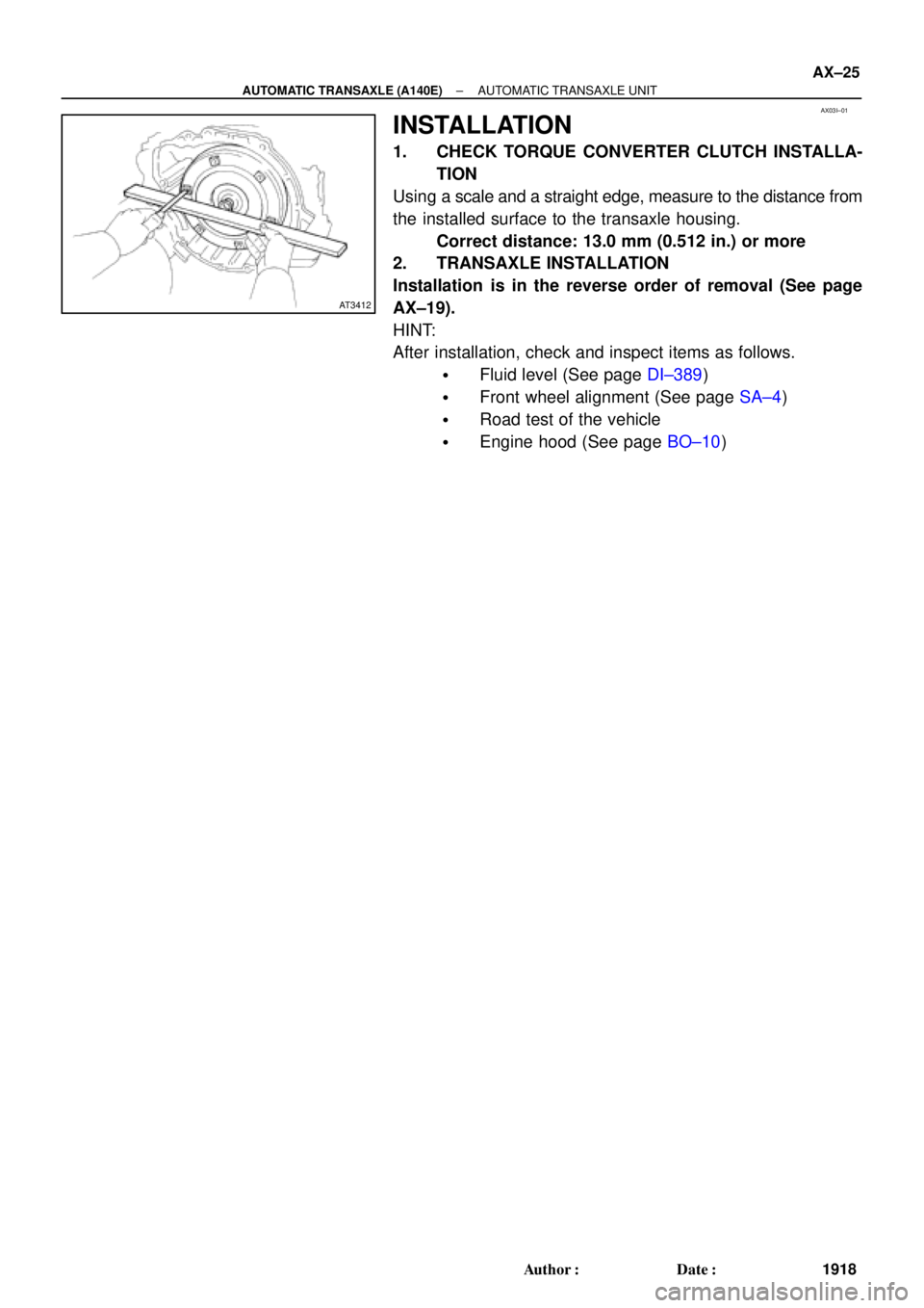
1. CHECK TORQUE CONVERTER CLUTCH INSTALLA-
TION
Using a scale and a straight edge, measure to the distance from
the installed surface to the transaxle housing.
Correct distance: 13.0 mm (0.512 in.) or more
2. TRANSAXLE INSTALLATION
Installation is in the reverse order of removal (See page
AX±19).
HINT:
After installation, check and inspect items as follows.
�Fluid level (See page DI±389)
�Front wheel alignment (See page SA±4)
�Road test of the vehicle
�Engine hood (See page BO±10)
Page 1791 of 4770

INTRODUCTIONGLOSSARY OF SAE AND TOYOTA TERMS ±
IN±6
GLOSSARY OF SAE AND TOYOTA TERMS
This glossary lists all SAE±J1930 terms and abbreviations used in this manual in compliance with SAE
recommendations, as well as their Toyota equivalents.
SAE
ABBREVIATIONSSAE TERMSTOYOTA TERMS
( )±±ABBREVIATIONS
A/CAir ConditioningAir Conditioner
ACLAir CleanerAir Cleaner
AIRSecondary Air InjectionAir Injection (AI)
APAccelerator Pedal±
B+Battery Positive Voltage+B, Battery Voltage
BAROBarometric Pressure±
CACCharge Air CoolerIntercooler
CARBCarburetorCarburetor
CFIContinuous Fuel Injection±
CKPCrankshaft PositionCrank Angle
CLClosed LoopClosed Loop
CMPCamshaft PositionCam Angle
CPPClutch Pedal Position±
CTOXContinuous Trap Oxidizer±
CTPClosed Throttle Position±
DFIDirect Fuel Injection (Diesel)Direct Injection (DI)
DIDistributor Ignition±
DLC1
DLC2
DLC3Data Link Connector 1
Data Link Connector 2
Data Link Connector 31: Check Connector
2: Toyota Diagnosis Communication Link (TDCL)
3: OBD@@@@@: [g 2] Diagnostic Connector
DTCDiagnostic Trouble CodeDiagnostic Code
DTMDiagnostic Test Mode±
ECLEngine Control Level±
ECMEngine Control ModuleEngine ECU (Electronic Control Unit)
ECTEngine Coolant TemperatureCoolant Temperature, Water Temperature (THW)
EEPROMElectrically Erasable Programmable Read Only
MemoryElectrically Erasable Programmable Read Only Memory
(EEPROM),
Erasable Programmable Read Only Memory(EPROM)
EFEEarly Fuel EvaporationCold Mixture Heater (CMH), Heat Control Valve (HCV)
EGRExhaust Gas RecirculationExhaust Gas Recirculation (EGR)
EIElectronic IgnitionToyota Distributorless Ignition (TDI)
EMEngine ModificationEngine Modification (EM)
EPROMErasable Programmable Read Only MemoryProgrammable Read Only Memory (PROM)
EVAPEvaporative EmissionEvaporative Emission Control (EVAP)
FCFan Control±
FEEPROMFlash Electrically Erasable Programmable
Read Only Memory±
FEPROMFlash Erasable Programmable Read Only Memory±
FFFlexible Fuel±
FPFuel PumpFuel Pump
GENGeneratorAlternator
GNDGroundGround (GND)
HO2SHeated Oxygen SensorHeated Oxygen Sensor (HO2S)
IN016±02
Page 1792 of 4770

IATIntake Air TemperatureIntake or Inlet Air Temperature
ICMIgnition Control Module±
IFIIndirect Fuel")
INTRODUCTIONGLOSSARY OF SAE AND TOYOTA TERMS ±
IN±7
IACIdle Air ControlIdle Speed Control (ISC)
IATIntake Air TemperatureIntake or Inlet Air Temperature
ICMIgnition Control Module±
IFIIndirect Fuel InjectionIndirect Injection
IFSInertia Fuel±Shutoff±
ISCIdle Speed Control±
KSKnock SensorKnock Sensor
MAFMass Air FlowAir Flow Meter
MAPManifold Absolute PressureManifold Pressure
Intake Vacuum
MCMixture Control
Electric Bleed Air Control Valve (EBCV)
Mixture Control Valve (MCV)
Electric Air Control Valve (EACV)
MDPManifold Differential Pressure±
MFIMultiport Fuel InjectionElectronic Fuel Injection (EFI)
MILMalfunction Indicator LampCheck Engine Light
MSTManifold Surface Temperature±
MVZManifold Vacuum Zone±
NVRAMNon±Volatile Random Access Memory±
O2SOxygen SensorOxygen Sensor, O2 Sensor (O2S)
OBDOn±Board DiagnosticOn±Board Diagnostic (OBD)
OCOxidation Catalytic ConverterOxidation Catalyst Converter (OC), CCo
OPOpen LoopOpen Loop
PAIRPulsed Secondary Air InjectionAir Suction (AS)
PCMPowertrain Control Module±
PNPPark/Neutral Position±
PROMProgrammable Read Only Memory±
PSPPower Steering Pressure±
PTOXPeriodic Trap OxidizerDiesel Particulate Filter (DPF)
Diesel Particulate Trap (DPT)
RAMRandom Access MemoryRandom Access Memory (RAM)
RMRelay Module±
ROMRead Only MemoryRead Only Memory (ROM)
RPMEngine SpeedEngine Speed
SCSuperchargerSupercharger
SCBSupercharger Bypass±
SFISequential Multiport Fuel InjectionElectronic Fuel Injection (EFI), Sequential Injection
SPLSmoke Puff Limiter±
SRIService Reminder Indicator±
SRTSystem Readiness Test±
STScan Tool±
TBThrottle BodyThrottle Body
TBIThrottle Body Fuel InjectionSingle Point Injection
Central Fuel Injection (Ci)
TCTurbochargerTurbocharger
TCCTorque Converter ClutchTorque Converter
TCMTransmission Control ModuleTransmission ECU (Electronic Control Unit)
TPThrottle PositionThrottle Position
TRTransmission Range±
Page 1797 of 4770
AUTOMATIC TRANSAXLEDESCRIPTION ±
AX±1
DESCRIPTION
GENERAL SPECIFICATIONS
Type of TransaxleA541E
Type of Engine1MZ±FE
Torque Converter Clutch Stall Torque Ratio1.8 : 1
Torque Converter Clutch Lock±up MechanismEquipped
Gear Ratio 1st Gear
2nd Gear
3rd Gear
O/D Gear
Reverse Gear2.810
1.549
1.000
0.735
2.296
Transaxle Number of Discs and Plates
O/D Direct Clutch (C
0)
Forward Clutch (C
1)
Direct Clutch (C
2)
2nd Brake (B
2)
First and Reverse Brake (B
3)
O/D Brake (B
0)
2 / 2
5 / 5
3 / 3
3 / 3
6 / 6
3 / 3
B1 Band Width mm (in.)25 (0.98)
ATF TypeATF D±@@@@@: [g 2] or DEXRON®@@@@@: [g
3](DEXRON®@@@@@: [g 2])
Capacity liter (US qts, Imp.qts) A/T
D/F6.75(7.1, 5.9)
0.85 (0.9, 0.7)
AX0CH±05
Page 1800 of 4770
AUTOMATIC TRANSAXLEOPERATION ±
AX±4
Power from the engine transmitted to the input shaft via the torque converter clutch is then transmitted
to the planetary gears by the operation of the clutch.
By operation of the brake and one±way clutch, either the planetary carrier or the planetary sun gear
are immobilized, altering the speed of revolution of the planetary gear unit.
Shift change is carried out by altering the combination of clutch and brake operation.
Each clutch and brake operates by hydraulic pressure; gear position is decided according to the throttle
opening angle and vehicle speed, and shift change automatically occurs.
The conditions of operation for each gear position are shown on the following illustrations:
Page 1815 of 4770
AUTOMATIC TRANSAXLECOMPONENT PARTS REMOVAL ±
AX±19
22. STAND TRANSAXLE ENGINE SIDE UPWARD
23. REMOVE OIL PUMP
NOTICE: Before removing the oil pump, remove the se-
cond coast brake piston.
(a) Remove the 7 bolts.
(b) Using SST, pull out the oil pump from the transaxle case.
SST 09350±32014
24. REMOVE O±RING FROM OIL PUMP
25. REMOVE DIRECT CLUTCH AND FORWARD CLUTCH
26. SEPARATE DIRECT CLUTCH AND FORWARD
CLUTCH
(a) Separate the direct clutch and forward clutch.
(b) Remove the thrust washer from direct clutch.
Page 1941 of 4770
200 mm
(7.87 in.)
± AUTOMATIC TRANSAXLE (A541E)THROTTLE CABLE
AX±13
1933 Author�: Date�:
THROTTLE CABLE
ON±VEHICLE REPAIR")
Q09982
AX03R±01
Q00225
Q00270
Q00270
Q057310.8 ± 1.5 mm (0.031±0.059 in.)200 mm
(7.87 in.)
± AUTOMATIC TRANSAXLE (A541E)THROTTLE CABLE
AX±13
1933 Author�: Date�:
THROTTLE CABLE
ON±VEHICLE REPAIR
1. REMOVE BATTERY
2. w/ Cruise Control:
REMOVE CRUISE CONTROL ACTUATOR
Remove the 3 bolts and cruise control actuator.
3. DISCONNECT THROTTLE CABLE FROM ENGINE
Disconnect the cable from the throttle linkage.
4. REMOVE PARK/NEUTRAL POSITION SWITCH
(See page AX±5)
5. REMOVE VALVE BODY
(See page AX±7)
6. REMOVE THROTTLE CABLE
(a) Remove the bolt and retaining plate.
(b) Pull out the cable from the transaxle case.
7. INSTALL THROTTLE CABLE INTO TRANSAXLE
CASE
(a) Make sure to push it in all the way.
(b) Install the retaining plate and bolt.
(c) Install and torque the bolt.
Torque: 5.4 N´m (55 kgf´cm, 48 in.´lbf)
8. INSTALL VALVE BODY
(See page AX±7)
9. IF THROTTLE CABLE IS NEW, STAKE STOPPER OR
PAINT MARK ON INNER CABLE
HINT:
New cables do not have a staked cable stopper.
(a) Bend the cable so there is a radius of about 200 mm (7.87
in.).
(b) Pull the inner cable lightly until slight resistance is felt, and
hold it there.
(c) Stake the stopper, 0.8±1.5 mm (0.031±0.059 in.) from the
end of outer cable.


 Remove")