Page 1556 of 4770
AC0LZ±02
Z19018
Connector Bracket
Glove Compartment
ECM
Foot Air Duct
No.2 Lower CoverBlower UnitCowl Side Trim
Blower Motor Connector
Blower Motor Blower Unit Case Air Inlet Damper
Control Cable
1MZ±FE engine:
A/C Amplifier
Front Door
Inside Scuff
Plate
Blower Resistor
Connecter
Blower Resistor AC±34
± AIR CONDITIONINGBLOWER UNIT
2516 Author�: Date�:
BLOWER UNIT
COMPONENTS
Page 1561 of 4770

AC0M4±02
N01143
W
N01150
± AIR CONDITIONINGCOMPRESSOR AND MAGNETIC CLUTCH
AC±39
2521 Author�: Date�:
COMPRESSOR AND MAGNETIC
CLUTCH
ON±VEHICLE INSPECTION
1. INSPECT COMPRESSOR FOR METALLIC SOUND
(a) Start engine.
(b) Check if there is a metallic sound from the compressor
when the A/C switch is on.
If metallic sound is heard, replace the compressor assembly.
2. INSPECT REFRIGERANT PRESSURE
See ºON±VEHICLE INSPECTIONº of AIR CONDITIONING
SYSTEM on page AC±3.
3. INSPECT COMPRESSOR LOCK SENSOR RESIS-
TANCE
(a) Disconnect the connector.
(b) Measure resistance between terminals 1 and 2.
Standard resistance: 65 ± 125 W at 20 °C (68 °F)
If resistance is not as specified, replace the compressor assem-
bly.
4. INSPECT VISUALLY FOR LEAKAGE OF REFRIGER-
ANT FROM SAFETY SEAL
Using a gas leak detector, check for leakage of refrigerant.
If there is any leakage, replace the compressor assembly.
5. CHECK FOR LEAKAGE OF GREASE FROM CLUTCH
BEARING
6. CHECK FOR SIGNS OF OIL ON PRESSURE PLATE OR
ROTOR
7. INSPECT MAGNETIC CLUTCH BEARING FOR NOISE
(a) Start engine.
(b) Check for abnormal noise from near the compressor
when the A/C switch is OFF.
If abnormal noise is being emitted, replace the magnetic clutch.
8. INSPECT MAGNETIC CLUTCH OPERATION
(a) Disconnect the connector.
(b) Connect the positive (+) lead from the battery to terminal
4 and the negative (±) lead to the body ground.
(c) Check that the magnetic clutch is energized.
If operation is not as specified, replace the magnetic clutch.
Page 1562 of 4770
AC0M5±02
I03331
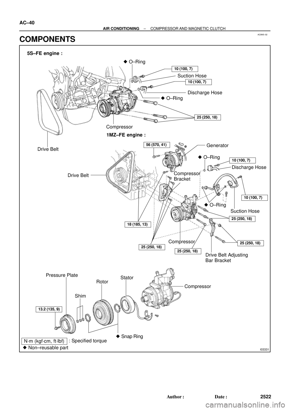
5S±FE engine :
Drive BeltCompressor� O±Ring
Suction Hose
Discharge Hose
10 (100, 7)
10 (100, 7)
� O±Ring
25 (250, 18)
1MZ±FE engine :
� O±Ring
Drive Belt
Drive Belt Adjusting
Bar BracketGenerator
Discharge Hose
10 (100, 7)
10 (100, 7)
25 (250, 18)
Compressor
25 (250, 18)
25 (250, 18)
ShimSuction Hose � O±Ring
25 (250, 18)
56 (570, 41)
18 (185, 13)
13.2 (135, 9)
Rotor Pressure Plate
: Specified torque
N´m (kgf´cm, ft´lbf)Stator
Compressor
� Snap Ring
� Non±reusable part
Compressor
Bracket AC±40
± AIR CONDITIONINGCOMPRESSOR AND MAGNETIC CLUTCH
2522 Author�: Date�:
COMPONENTS
Page 1563 of 4770

AC0M6±02
N20277
P19978
± AIR CONDITIONINGCOMPRESSOR AND MAGNETIC CLUTCH
AC±41
2523 Author�: Date�:
REMOVAL
1. RUN ENGINE AT IDLE SPEED WITH A/C ON FOR
APPROX.10 MINUTES
2. STOP ENGINE
3. DISCONNECT NEGATIVE (±) TERMINAL CABLE
FROM BATTERY
4. DISCHARGE REFRIGERANT FROM REFRIGERATION
SYSTEM
5. REMOVE DRIVE BELT
(See page AC±17)
6. 1MZ±FE engine models:
REMOVE SUCTION HOSE
(a) Remove the suction hose clamping bolt.
(b) Disconnect the wire harness clamp.
(c) Loosen the nut and bolts and remove the suction hose.
NOTICE:
Cap the open fittings immediately to keep moisture or dirt
out of the system.
7. 1MZ±FE engine models:
DISCONNECT DISCHARGE HOSE
Remove the bolt and disconnect the hose.
NOTICE:
Cap the open fittings immediately to keep moisture or dirt
out of the system.
8. 1MZ±FE engine models:
REMOVE GENERATOR
(a) Disconnect the generator connector.
(b) Remove the nut, and disconnect the generator wire.
(c) Disconnect the wire harness from the clip.
(d) Remove the pivot bolt, plate washer, adjusting lock bolt
and generator.
Page 1564 of 4770
N20261
5S±FE
N20240
5S±FE
Z19152
1MZ±FE
Z19149
1MZ±FE AC±42
± AIR CONDITIONINGCOMPRESSOR AND MAGNETIC CLUTCH
2524 Author�: Date�:
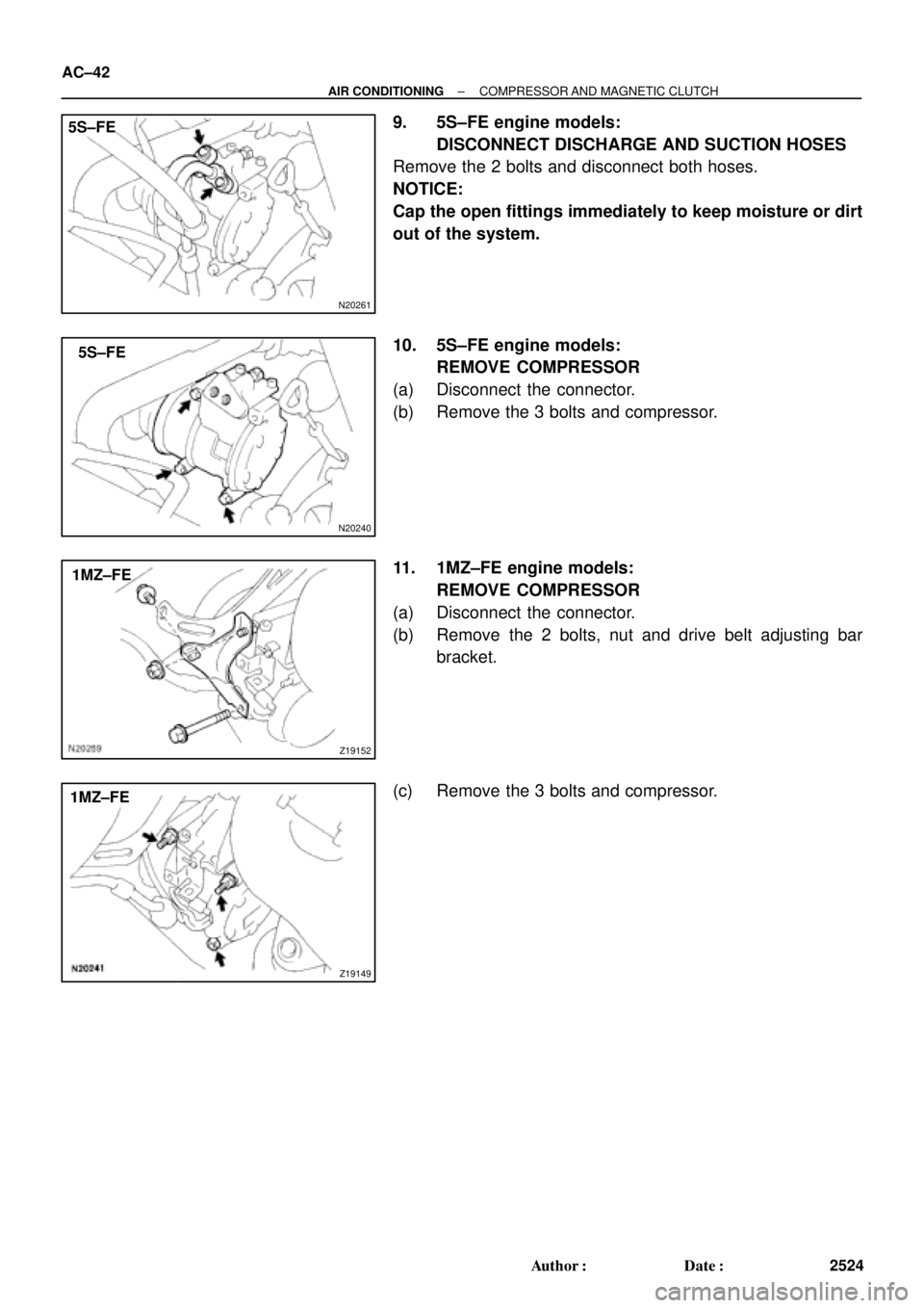
9. 5S±FE engine models:
DISCONNECT DISCHARGE AND SUCTION HOSES
Remove the 2 bolts and disconnect both hoses.
NOTICE:
Cap the open fittings immediately to keep moisture or dirt
out of the system.
10. 5S±FE engine models:
REMOVE COMPRESSOR
(a) Disconnect the connector.
(b) Remove the 3 bolts and compressor.
11. 1MZ±FE engine models:
REMOVE COMPRESSOR
(a) Disconnect the connector.
(b) Remove the 2 bolts, nut and drive belt adjusting bar
bracket.
(c) Remove the 3 bolts and compressor.
Page 1569 of 4770

(B)
± AIR CONDITIONINGCOMPRESSOR AND MAGNETIC CLUTCH
AC±47
2529 Author�: Date�:
INSTALLATION
1. 5S±FE engine models:
INSTALL COMPRESSOR
(a) Install the compressor with 3 bolts.")
AC0M9±02
N20259
(A)
(B)
± AIR CONDITIONINGCOMPRESSOR AND MAGNETIC CLUTCH
AC±47
2529 Author�: Date�:
INSTALLATION
1. 5S±FE engine models:
INSTALL COMPRESSOR
(a) Install the compressor with 3 bolts.
Torque: 25 N´m (250 kgf´cm, 18 ft´lbf)
(b) Connect the connector.
2. 1MZ±FE engine models:
INSTALL COMPRESSOR
(a) Install the compressor with 3 bolts.
Torque: 25 N´m (250 kgf´cm, 18 ft´lbf)
(b) Install the drive belt adjusting bar bracket with 2 bolts and
nut.
Torque:
Bolt (A): 25 N´m (250 kgf´cm, 18 ft´lbf)
Bolt (B): 18 N´m (185 kgf´cm, 13 ft´lbf)
Nut: 25 N´m (250 kgf´cm, 18 ft´lbf)
(c) Connect the connector.
3. 5S±FE engine models:
CONNECT DISCHARGE AND SUCTION HOSE
Connect the both hoses with the 2 bolts.
Torque: 10 N´m (100 kgf´cm, 7 ft´lbf)
NOTICE:
Hoses should be connected immediately after the caps
have been removed.
HINT:
Lubricate 2 new O±rings with compressor oil and install the
tubes.
4. 1MZ±FE engine models:
INSTALL GENERATOR
(a) Mount generator on the generator bracket with the pivot
bolt and adjusting lock bolt. Do not tighten the bolts yet.
(b) Connect the generator connector.
(c) Connect the generator wire with the nut.
Page 1570 of 4770

AC±48
± AIR CONDITIONINGCOMPRESSOR AND MAGNETIC CLUTCH
2530 Author�: Date�:
5. 1MZ±FE engine models:
CONNECT DISCHARGE HOSE
Connect the discharge hose with the bolt.
Torque: 10 N´m (100 kgf´cm, 7 ft´lbf)
NOTICE:
Hoses should be connected immediately after the caps
have been removed.
HINT:
Lubricate a new O±ring with compressor oil and install the tube.
6. INSTALL SUCTION HOSE
(a) Install the suction hose and tighten the bolt and nut.
Torque:
Piping joint: 32 N´m (330 kgf´cm, 24 ft´lbf)
Block joint: 10 N´m (100 kgf´cm, 7 ft´lbf)
HINT:
Lubricate 2 new O±rings with compressor oil and install the
hose.
(b) Install the suction hose clamping bolt.
(c) Connect the wire harness clamp.
7. INSTALL AND CHECK DRIVE BELT
(See page AC±18, AC±16)
8. CONNECT NEGATIVE (±) TERMINAL CABLE TO BAT-
TERY
9. EVACUATE AIR FROM REFRIGERATION SYSTEM
AND CHARGE SYSTEM WITH REFRIGERANT
Specified amount: 800 ± 50 g (28.22 ± 1.76 oz.)
10. INSPECT FOR LEAKAGE OF REFRIGERANT
Using a gas leak detector, check for leakage of refrigerant.
If there is leakage, check the tightening torque at the joints.
11. INSPECT A/C OPERATION
Page 1576 of 4770
N20451
AC±54
± AIR CONDITIONINGCONDENSER
2536 Author�: Date�:
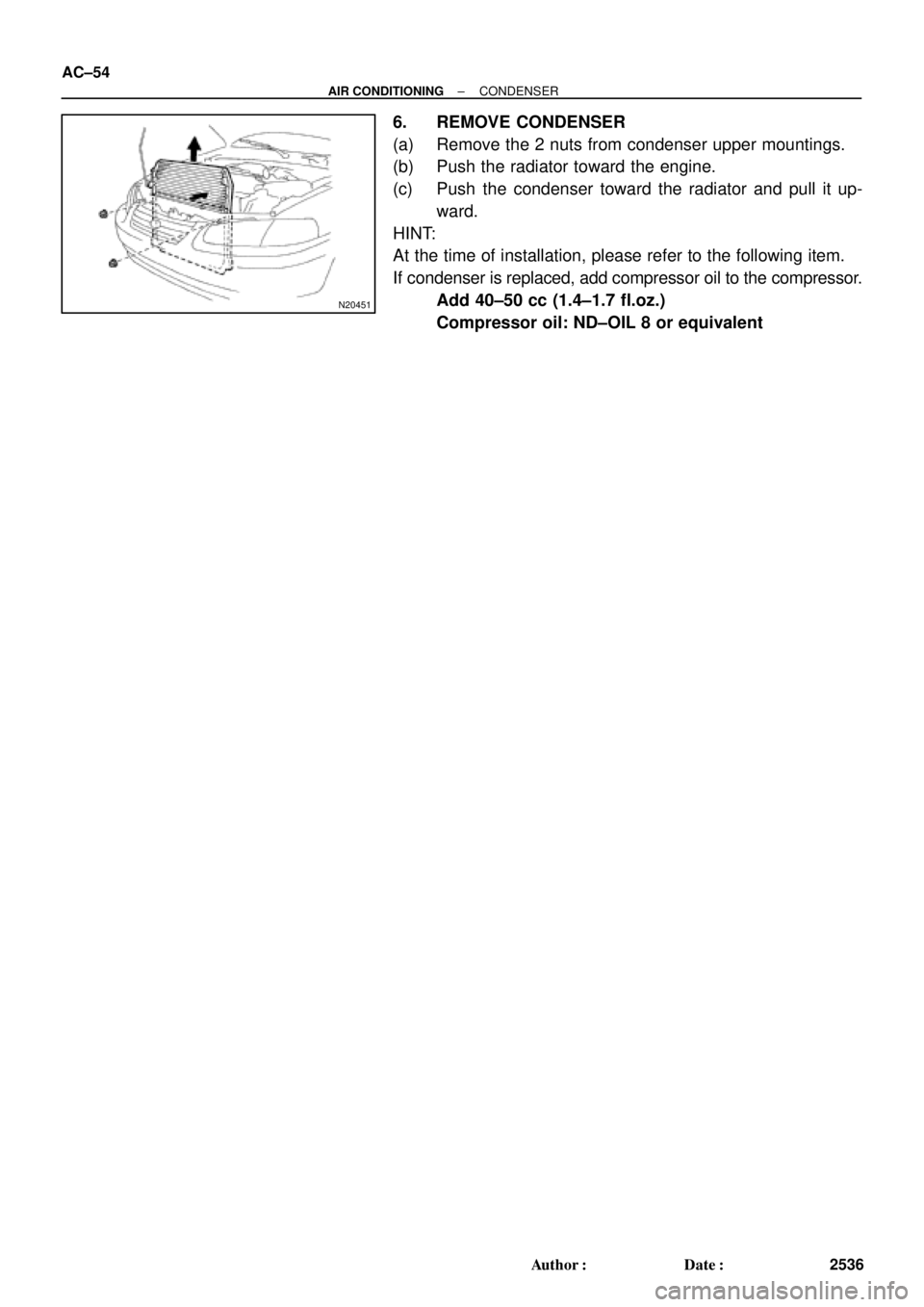
6. REMOVE CONDENSER
(a) Remove the 2 nuts from condenser upper mountings.
(b) Push the radiator toward the engine.
(c) Push the condenser toward the radiator and pull it up-
ward.
HINT:
At the time of installation, please refer to the following item.
If condenser is replaced, add compressor oil to the compressor.
Add 40±50 cc (1.4±1.7 fl.oz.)
Compressor oil: ND±OIL 8 or equivalent