Page 1578 of 4770
AC21Z±01
N20692
I09156
I09155
I09154
AC±56
± AIR CONDITIONINGHEATER RADIATOR
2538 Author�: Date�:
HEATER RADIATOR
REMOVAL
1. DRAIN ENGINE COOLANT FROM RADIATOR
HINT:
It is not necessary to drain out all the coolant.
2. DISCONNECT WATER HOSES FROM A/C UNIT
(See page AC±27)
3. REMOVE NO. 1 LOWER INSTRUMENT PANEL
4. REMOVE LH INSTRUMENT LOWER PANEL
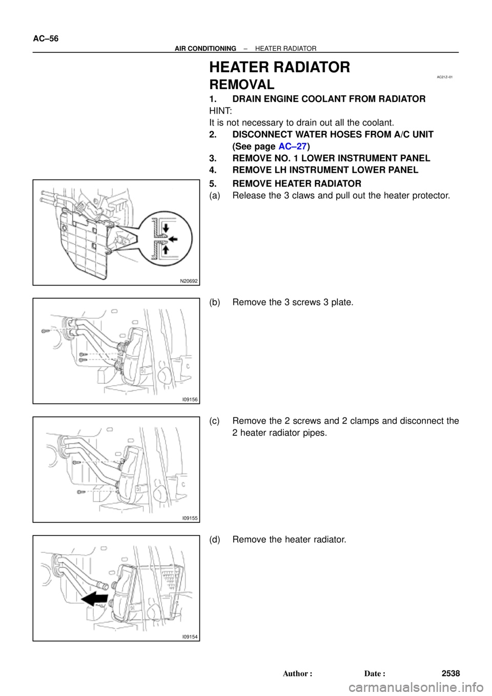
5. REMOVE HEATER RADIATOR
(a) Release the 3 claws and pull out the heater protector.
(b) Remove the 3 screws 3 plate.
(c) Remove the 2 screws and 2 clamps and disconnect the
2 heater radiator pipes.
(d) Remove the heater radiator.
Page 1581 of 4770
AC0MM±02
± AIR CONDITIONINGEXPANSION VALVE
AC±59
2541 Author�: Date�:
EXPANSION VALVE
ON±VEHICLE INSPECTION
1. CHECK QUANTITY OF GAS DURING REFRIGERATION CYCLE
2. SET ON MANIFOLD GAUGE SET (See page AC±19)
3. RUN ENGINE
Run the engine at 1,500 rpm for at least 5 minutes.
Then check that the high pressure reading is 1.37 ± 1.57 MPa (14 ± 16 kgf/cm
2, 199 ± 228 psi).
4. CHECK EXPANSION VALVE
If the expansion valve is faulty, the low pressure reading will drop to 0 kPa (0 kgf/cm
2, 0 psi).
HINT:
When the low pressure drops to 0 kPa (0 kgf/cm
2, 0 psi), check the receiver's IN and OUT sides is no temper-
ature difference.
Page 1589 of 4770

196 kPa
(2.0 kgf/cm
2, 28 psi)High pressure side
3, 140 kPa
(32.0kgf/cm2, 455 psi)
OFF (No Continuity")
N20291
AC0N2±02
Z13470
Magnetic clutch control
Low pressure side
ON (Continuity)
196 kPa
(2.0 kgf/cm
2, 28 psi)High pressure side
3, 140 kPa
(32.0kgf/cm2, 455 psi)
OFF (No Continuity)
Z13471
1, 226 kPa
(12.5 kgf/cm2, 178 psi)OFF
(No Continuity) Condenser fan control
ON
(Continuity)150 kPa
(15.5 kgf/cm
2, 220 psi)
± AIR CONDITIONINGPRESSURE SWITCH
AC±67
2549 Author�: Date�:
PRESSURE SWITCH
ON±VEHICLE INSPECTION
1. SET ON MANIFOLD GAUGE SET
(See page AC±19)
2. DISCONNECT CONNECTOR FROM PRESSURE
SWITCH
3. RUN ENGINE AT APPROX. 1,500 RPM
4. Magnetic clutch control:
INSPECT PRESSURE SWITCH OPERATION
(a) Connect the positive (+) lead from the ohmmeter to termi-
nal 4 and negative (±) lead to terminal 1.
(b) Check continuity between terminals when refrigerant
pressure is changed, as shown in the illustration.
If operation is not as specified, replace the pressure switch.
5. Condenser fan control:
INSPECT PRESSURE SWITCH OPERATION
(a) Connect the positive (+) lead from the ohmmeter to termi-
nal 2 and negative (±) lead to terminal 3.
(b) Check continuity between terminals when refrigerant
pressure is changed, as shown in the illustration.
If operation is not as specified, replace the pressure switch.
6. STOP ENGINE AND REMOVE MANIFOLD GAUGE
SET
7. CONNECT CONNECTOR TO PRESSURE SWITCH
Page 1592 of 4770
I09189
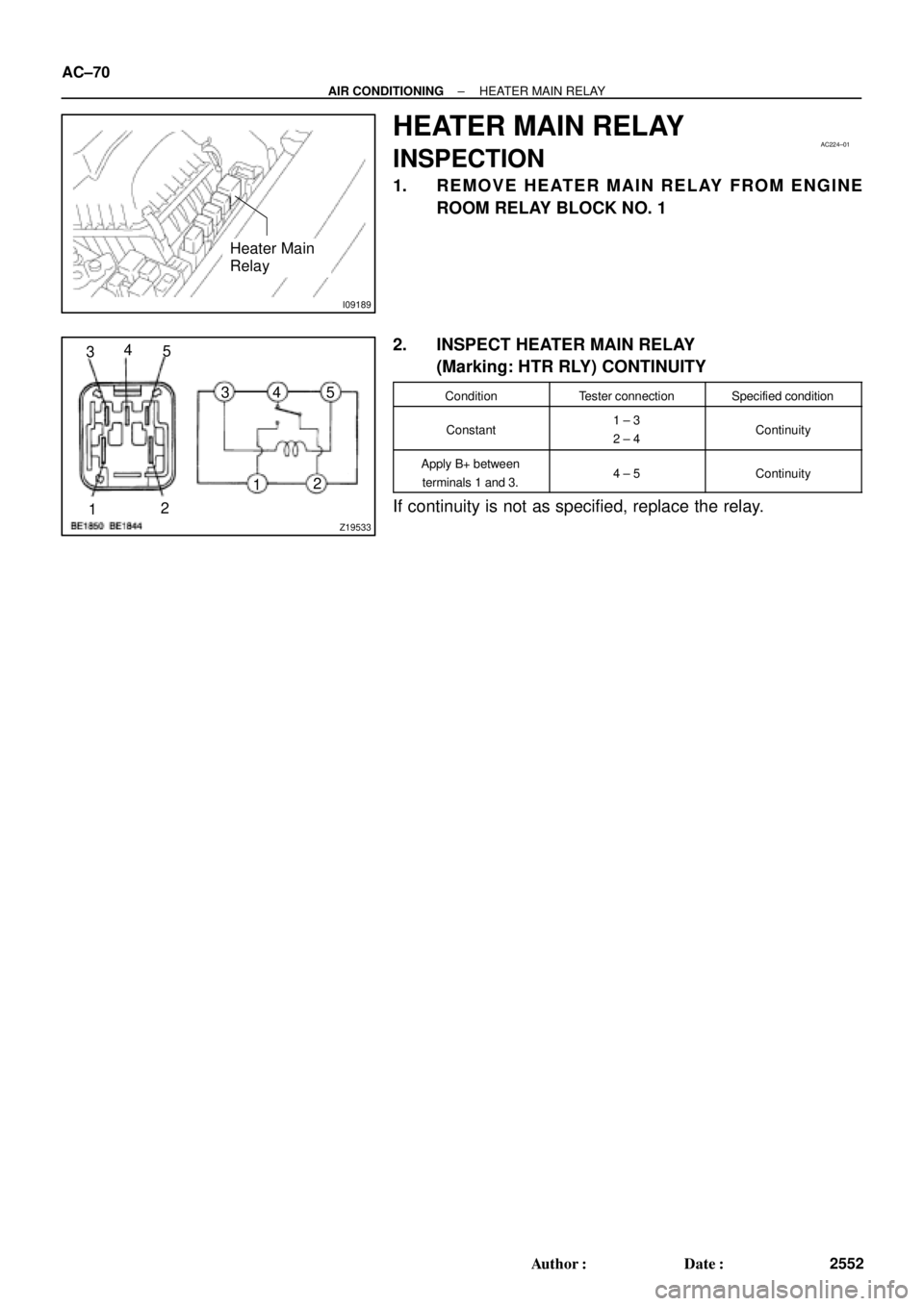
Heater Main
Relay
AC224±01
Z19533
34
5
1212 34 5 AC±70
± AIR CONDITIONINGHEATER MAIN RELAY
2552 Author�: Date�:
HEATER MAIN RELAY
INSPECTION
1. REMOVE HEATER MAIN RELAY FROM ENGINE
ROOM RELAY BLOCK NO. 1
2. INSPECT HEATER MAIN RELAY
(Marking: HTR RLY) CONTINUITY
ConditionTester connectionSpecified condition
Constant1 ± 3
2 ± 4Continuity
Apply B+ between
terminals 1 and 3.4 ± 5Continuity
If continuity is not as specified, replace the relay.
Page 1593 of 4770
I09189
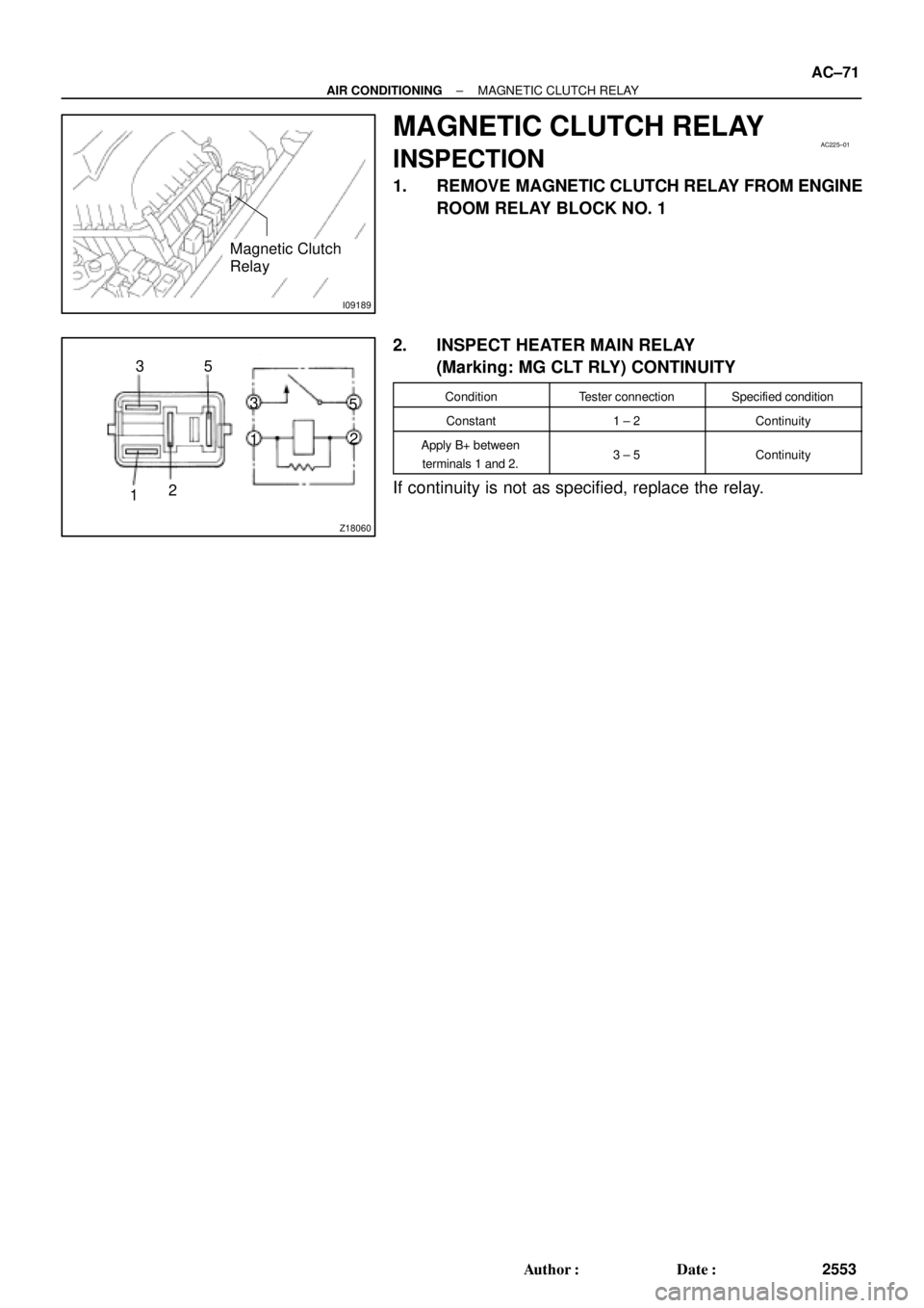
Magnetic Clutch
Relay
AC225±01
Z18060
35
1212 3
5
± AIR CONDITIONINGMAGNETIC CLUTCH RELAY
AC±71
2553 Author�: Date�:
MAGNETIC CLUTCH RELAY
INSPECTION
1. REMOVE MAGNETIC CLUTCH RELAY FROM ENGINE
ROOM RELAY BLOCK NO. 1
2. INSPECT HEATER MAIN RELAY
(Marking: MG CLT RLY) CONTINUITY
ConditionTester connectionSpecified condition
Constant1 ± 2Continuity
Apply B+ between
terminals 1 and 2.3 ± 5Continuity
If continuity is not as specified, replace the relay.
Page 1594 of 4770
S05390
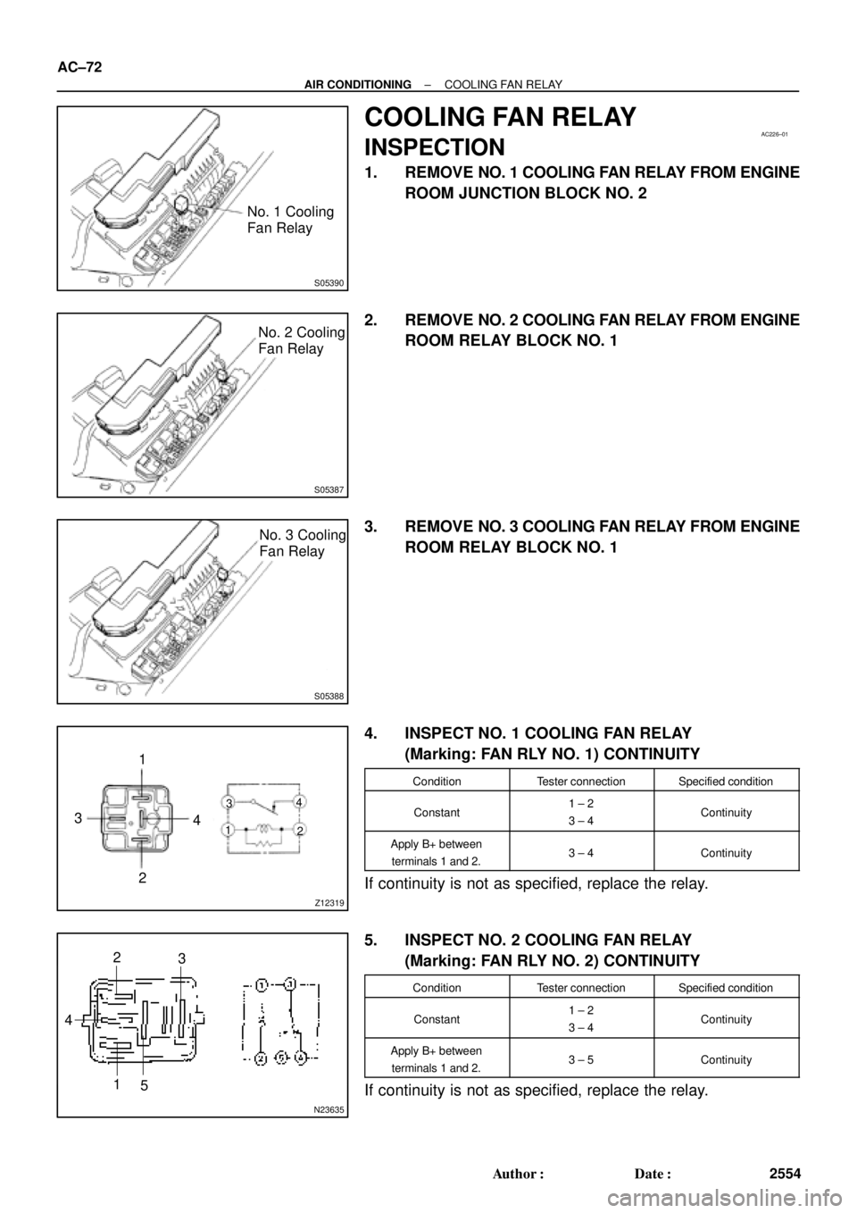
No. 1 Cooling
Fan Relay
AC226±01
S05387
No. 2 Cooling
Fan Relay
S05388
No. 3 Cooling
Fan Relay
Z12319
1
3
24
1
2 34
N23635
5 1 42
3 AC±72
± AIR CONDITIONINGCOOLING FAN RELAY
2554 Author�: Date�:
COOLING FAN RELAY
INSPECTION
1. REMOVE NO. 1 COOLING FAN RELAY FROM ENGINE
ROOM JUNCTION BLOCK NO. 2
2. REMOVE NO. 2 COOLING FAN RELAY FROM ENGINE
ROOM RELAY BLOCK NO. 1
3. REMOVE NO. 3 COOLING FAN RELAY FROM ENGINE
ROOM RELAY BLOCK NO. 1
4. INSPECT NO. 1 COOLING FAN RELAY
(Marking: FAN RLY NO. 1) CONTINUITY
ConditionTester connectionSpecified condition
Constant1 ± 2
3 ± 4Continuity
Apply B+ between
terminals 1 and 2.3 ± 4Continuity
If continuity is not as specified, replace the relay.
5. INSPECT NO. 2 COOLING FAN RELAY
(Marking: FAN RLY NO. 2) CONTINUITY
ConditionTester connectionSpecified condition
Constant1 ± 2
3 ± 4Continuity
Apply B+ between
terminals 1 and 2.3 ± 5Continuity
If continuity is not as specified, replace the relay.
Page 1596 of 4770

AC0N6±02
N20290
21
A AC±74
± AIR CONDITIONINGCONDENSER FAN
2556 Author�: Date�:
CONDENSER FAN
ON±VEHICLE INSPECTION
1. INSPECT CONDENSER FAN OPERATION
Inspect the fan operation, as shown in the chart below.
Test conditions:
�Ignition switch ON
�Blower speed control switch position ºHIº
�A/C switch ON
ConditionFan operation (Fan speed)
Engine coolant temperature
83°C (181°F) or belowNot rotate
Engine coolant temperature
98°C (208°F) or aboveRotate
Refrigerant pressure is less than
1,520 kPa (15.5 kgf/cm2, 220 psi)Not rotate (Low Speed)
Refrigerant pressure is 1,520 kPa
(15.5 kgf/cm2, 220 psi) or aboveRotate (High Speed)
If operation is not as specified, proceed next inspection.
2. INSPECT CONDENSER FAN MOTOR OPERATION
(a) Disconnect the fan connector.
(b) Connect the battery and ammeter to the connector, as
shown in the illustation.
(c) Check that the fan rotates smoothly, and then check that
the reading on the ammeter.
Specified amperage: 10.1 ± 1.8 A at 20 °C (68 °F)
�If operation is not as specified, replace the fan mo-
tor.
�If operation is as specified, check the pressure
switch, cooling fan relays and engine coolant temp.
switch.
Page 1598 of 4770
AC0N8±02
AC±76
± AIR CONDITIONINGCONDENSER FAN
2558 Author�: Date�:
REMOVAL
1. 1MZ±FE engine models only:
DRAIN ENGINE COOLANT FROM RADIATOR
HINT:
It is not necessary to drain out all the coolant.
2. 1MZ±FE engine models only:
DISCONNECT UPPER RADIATOR HOSE
3. REMOVE CONDENSER FAN
(a) Disconnect the connector.
(b) Remove the 4 bolts and fan.