Page 1638 of 4770
AUTOMATIC TRANSAXLEOPERATION ±
AX±5
Power from the engine transmitted to the input shaft via the torque converter is then transmitted to the
planetary gears by the operation of the clutch.
By operation of the brake and one±way clutch, either the planetary carrier or the planetary sun gear
are immobilized, altering the speed of revolution of the planetary gear unit.
Shift change is carried out by altering the combination of clutch and brake operation.
Each clutch and brake operates by hydraulic pressure; gear position is decided according to the throttle
opening angle and vehicle speed, and shift change automatically occurs.
The conditions of operation for each gear position are shown on the following illustrations:
Page 1767 of 4770
200 mm
(7.87 in.)
± AUTOMATIC TRANSAXLE (A140E)THROTTLE CABLE
AX±9
1902 Author�: Date�:
THROTTLE CABLE
ON±VEHICLE REPAIR
1. DISCONNECT THROT")
AX039±01
Q10052
Q10339
0.8 ± 1.5 mm(0.031 ± 0.059 in.)200 mm
(7.87 in.)
± AUTOMATIC TRANSAXLE (A140E)THROTTLE CABLE
AX±9
1902 Author�: Date�:
THROTTLE CABLE
ON±VEHICLE REPAIR
1. DISCONNECT THROTTLE CABLE
(a) Disconnect the cable from the throttle linkage.
(b) Disconnect the cable from the cable clamps in the engine
compartment.
2. REMOVE PARK/NEUTRAL POSITION SWITCH
(See page AX±4)
3. REMOVE VALVE BODY (See page AX±5)
4. REMOVE THROTTLE CABLE
(a) Remove the retaining bolt and plate.
(b) Pull out the cable from the transaxle case.
5. IF THROTTLE CABLE IS NEW, STAKE STOPPER OR
PAINT MARK ON INNER CABLE
HINT:
New cable does not have a staked cable stopper.
(a) Bend the cable to ensure a radius of about 200 mm (7.87
in.).
(b) Pull the inner cable lightly until a slight resistance is felt,
and hold it there.
(c) Stake the stopper, 0.8 ± 1.5 mm (0.031 ± 0.059 in.) from
the end of the outer cable.
(d) Install a new O±ring to the throttle cable.
(e) Push in the throttle cable and install the retaining bolt.
6. INSTALL VALVE BODY (See page AX±5)
7. INSTALL PARK/NEUTRAL POSITION SWITCH
(See page AX±4)
8. CONNECT THROTTLE CABLE
9. FILL FLUID AND CHECK FLUID LEVEL
(See page DI±389)
10. ADJUST THROTTLE CABLE (See page DI±389)
Page 1775 of 4770
AX03G±01
Q10053
14 (145, 10)
No.1 Exhaust Pipe Support BracketClip Engine Hood
Air Cleaner Assembly
14 (145, 10)
Starter
Cruise Control Actuator
RH Drive Shaft
42 (430, 31)66 (670, 48)
39 (400, 29)
39 (400, 29)
39 (400, 29)
Hold Down Clamp
Manifold Stay
Stiffener
PlateBattery
Battery Tray � Snap Ring
�
32 (330, 24)
27 (280, 20)
Torque Converter
Clutch
x6
42 (430, 31)
42 (430, 31)
Stiffener Plate66 (670, 48)
42 (430, 31)
Exhaust
Manifold Stay66 (670, 48)
� Snap RingLH Drive Shaft
Plug for Line Pressure Test
Rear End Plate
15 (150, 11)
19 (195, 14)
25 (250, 18)
Oil Pan Insulator Shift Control Cable
N´m (kgf´cm, ft´lbf): Specified torque
� Non±reusable partTMMK
TMC
± AUTOMATIC TRANSAXLE (A140E)AUTOMATIC TRANSAXLE UNIT
AX±17
1910 Author�: Date�:
AUTOMATIC TRANSAXLE UNIT
COMPONENTS
Page 1776 of 4770
RH Rear
Lower Brace
Steering Return Pipe
19 (195, 14)
FR Engine Mounting
Stabilizer Bar Link
Front Suspension
Member
�
Front Ex")
Q10054
RH Fender Apron seal
RR Engine Mounting
Stabilizer Bar
10 (100, 7)RH Rear
Lower Brace
Steering Return Pipe
19 (195, 14)
FR Engine Mounting
Stabilizer Bar Link
Front Suspension
Member
�
Front Exhaust Pipe
RH Front Lower Brace
LH Engine Mounting
66 (670, 48)
64 (650, 47)
39 (400, 29)
181 (1,850, 134)
LH Rear Lower Brace
32 (330, 24)
36 (370, 27)
181 (1,850, 134)
127 (1,300, 94)80 (820, 59)
TMC Made : 80 (820, 59)
TMMK Made :
Green Color Bolt : 66 (670, 48)
Silver Color Bolt : 44 (450, 32)
TMC Made : 80 (820, 59)
TMMK Made :
Green Color Bolt : 66 (670, 48)
Silver Color Bolt : 44 (450, 32)LH Front
Lower Brace
36 (370, 27)181 (1,850, 134)
56 (570, 41)
�
�� � Gasket
62 (630, 46)
Tie Rod End
Lock Nut Cap
Engine Under CoverLH Fender Liner � Gasket
�
Exhaust Pipe No.1 Support Bracket
33 (330, 24)
33 (330, 24)
Exhaust Pipe
ClampLH Fender Liner
LH Fender Apron Seal
� Cotter Pin
49 (500, 36)
294 (3,000, 217)
Center Engine Under Cover
N´m (kgf´cm, ft´lbf): Specified torque
� Non±reusable part AX±18
± AUTOMATIC TRANSAXLE (A140E)AUTOMATIC TRANSAXLE UNIT
1911 Author�: Date�:
Page 1777 of 4770
AUTOMATIC TRANSAXLE UNIT
AX±19
1912 Author�: Date�:
REMOVAL
1. REMOVE BATTERY
2. REMOVE AIR CLEANER ASSEMBLY
3. DISCONNECT THROTTLE")
AX03H±01
Q10055
Q00211
Q10056
Q10057
± AUTOMATIC TRANSAXLE (A140E)AUTOMATIC TRANSAXLE UNIT
AX±19
1912 Author�: Date�:
REMOVAL
1. REMOVE BATTERY
2. REMOVE AIR CLEANER ASSEMBLY
3. DISCONNECT THROTTLE CABLE
4. w/ CRUISE CONTROL:
REMOVE CRUISE CONTROL ACTUATOR
(a) Disconnect the connector.
(b) Remove the 3 bolts and disconnect cruise control actua-
tor with the bracket.
5. DISCONNECT OIL COOLER HOSE
6. DISCONNECT VEHICLE SPEED SENSOR CONNEC-
TOR
7. DISCONNECT PARK/NEUTRAL POSITION SWITCH
CONNECTOR
8. DISCONNECT SHIFT SOLENOID VALVE NO.1 AND
NO.2 CONNECTOR
9. DISCONNECT SHIFT SOLENOID VALVE SL CONNEC-
TOR
10. REMOVE 2 FRONT SIDE ENGINE MOUNTING BOLTS
Torque:
TMC made: 80 N´m (820 kgf´cm, 59 ft´lbf)
TMMK made:
Green color bolt: 66 N´m (670 kgf´cm, 48 ft´lbf)
Silver color bolt: 44 N´m (450 kgf´cm, 32 ft´lbf)
11. DISCONNECT 2 GROUND CABLES
12. REMOVE STARTER
(a) Disconnect the connector and remove the nut.
(b) Remove the 2 bolts, shift cable clamp and starter.
Torque: 39 N´m (400 kgf´cm, 29 ft´lbf)
13. REMOVE 3 TRANSAXLE±TO±ENGINE BOLTS
Torque: 66 N´m (670 kgf´cm, 48 ft´lbf)
Page 1778 of 4770
AUTOMATIC TRANSAXLE UNIT
1913 Author�: Date�:
14. REMOVE EXHAUST MANIFOLD STAY
Remove the 2 bolts and exhaust manifold stay.
Torque: 42 N´m (")
Q10058
Q10059
Q00251
AX±20
± AUTOMATIC TRANSAXLE (A140E)AUTOMATIC TRANSAXLE UNIT
1913 Author�: Date�:
14. REMOVE EXHAUST MANIFOLD STAY
Remove the 2 bolts and exhaust manifold stay.
Torque: 42 N´m (430 kgf´cm, 31 ft´lbf)
15. REMOVE TRANSAXLE±TO±ENGINE BOLT
Torque: 66 N´m (670 kgf´cm, 48 ft´lbf)
16. REMOVE ENGINE HOOD
(a) Disconnect the washer pipe.
(b) Remove the 4 bolts and engine hood.
Torque: 14 N´m (145 kgf´cm, 10 ft´lbf)
17. RAISE AND SUPPORT VEHICLE SECURELY
18. REMOVE FRONT WHEELS
Torque: 103 N´m (1,050 kgf´cm, 76 ft´lbf)
19. REMOVE ENGINE UNDER COVER AND CENTER EN-
GINE UNDER COVER
20. DISCONNECT SHIFT CONTROL CABLE
(a) Remove the nut and disconnect the shift control cable
from the park/neutral position switch.
Torque: 15 N´m (150 kgf´cm, 11 ft´lbf)
(b) Remove the clip and disconnect the shift control cable
from the bracket.
21. REMOVE DIFFERENTIAL FLUID DRAIN PLUG AND
GASKET
HINT:
At the time of installation, please refer to the following item.
Replace the used gasket with a new gasket.
22. DRAIN DIFFERENTIAL FLUID
23. REMOVE LH AND RH FENDER APRON SEALS
24. REMOVE LH AND RH DRIVE SHAFTS
(See page SA±17)
Page 1779 of 4770
AUTOMATIC TRANSAXLE UNIT
AX±21
1914 Author�: Date�:
25. REMOVE EXHAUST FRONT PIPE
(a) Remove the 2 nuts and exhaust front pipe clamp.
Torque:")
Q10060
Q00068
Q08532
Q10061
± AUTOMATIC TRANSAXLE (A140E)AUTOMATIC TRANSAXLE UNIT
AX±21
1914 Author�: Date�:
25. REMOVE EXHAUST FRONT PIPE
(a) Remove the 2 nuts and exhaust front pipe clamp.
Torque: 33 N´m (330 kgf´cm, 24 ft´lbf)
(b) Remove the 2 bolts and exhaust pipe No.1 support brack-
et.
Torque: 33 N´m (330 kgf´cm, 24 ft´lbf)
(c) Remove the 3 nuts.
Torque: 62 N´m (630 kgf´cm, 46 ft´lbf)
HINT:
At the time of installation, please refer to the following item.
Replace the used nuts with new ones.
(d) Remove the 2 bolts, nuts and front exhaust pipe.
Torque: 56 N´m (570 kgf´cm, 41 ft´lbf)
HINT:
At the time of installation, please refer to the following item.
Replace the used nuts with new ones.
(e) Remove the 2 gaskets.
HINT:
At the time of installation, please refer to the following item.
Replace the used gaskets with new ones.
26. REMOVE FRONT SIDE ENGINE MOUNTING INSULA-
TOR BOLT
Torque:
TMC made: 80 N´m (820 kgf´cm, 59 ft´lbf)
TMMK made:
Green color bolt: 66 N´m (670 kgf´cm, 48 ft´lbf)
Silver color bolt: 44 N´m (450 kgf´cm, 32 ft´lbf)
27. REMOVE REAR SIDE ENGINE MOUNTING NUT
(a) Remove the 2 grommets.
(b) Remove the 3 nuts.
Torque: 66 N´m (670 kgf´cm, 48 ft´lbf)
28. REMOVE LEFT SIDE TRANSAXLE MOUNTING NUT
(a) Remove the 2 grommets.
(b) Remove the 2 nuts.
Torque: 80 N´m (820 kgf´cm, 59 ft´lbf)
Page 1780 of 4770
Q10062
Q10063
Q06479
Q10041
Q10037
AX±22
± AUTOMATIC TRANSAXLE (A140E)AUTOMATIC TRANSAXLE UNIT
1915 Author�: Date�:
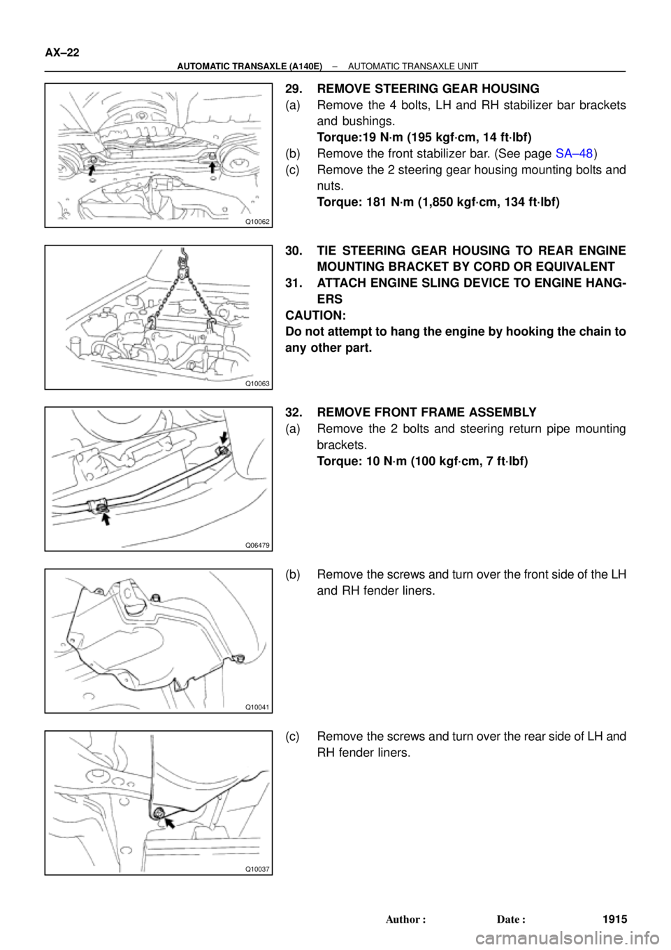
29. REMOVE STEERING GEAR HOUSING
(a) Remove the 4 bolts, LH and RH stabilizer bar brackets
and bushings.
Torque:19 N´m (195 kgf´cm, 14 ft´lbf)
(b) Remove the front stabilizer bar. (See page SA±48)
(c) Remove the 2 steering gear housing mounting bolts and
nuts.
Torque: 181 N´m (1,850 kgf´cm, 134 ft´lbf)
30. TIE STEERING GEAR HOUSING TO REAR ENGINE
MOUNTING BRACKET BY CORD OR EQUIVALENT
31. ATTACH ENGINE SLING DEVICE TO ENGINE HANG-
ERS
CAUTION:
Do not attempt to hang the engine by hooking the chain to
any other part.
32. REMOVE FRONT FRAME ASSEMBLY
(a) Remove the 2 bolts and steering return pipe mounting
brackets.
Torque: 10 N´m (100 kgf´cm, 7 ft´lbf)
(b) Remove the screws and turn over the front side of the LH
and RH fender liners.
(c) Remove the screws and turn over the rear side of LH and
RH fender liners.


No.1 Exhaust Pipe Support BracketClip Engine Hood
Air Cleaner Assembly
14 (145, 10)
Starter
Cruise Control Actuator
RH Drive Shaft
42 (430, 31)66 (670, 48)
39 (400, 29)
3")