Page 1956 of 4770
AUTOMATIC TRANSAXLE UNIT
1948 Author�: Date�:
(d) Remove the 6 bolts and 4 nuts.
Torque:
19 mm head bo")
Q10172
Front
Q10064
Rear
Q04660
Q10036
Z14284
Left and lower AX±28
± AUTOMATIC TRANSAXLE (A541E)AUTOMATIC TRANSAXLE UNIT
1948 Author�: Date�:
(d) Remove the 6 bolts and 4 nuts.
Torque:
19 mm head bolt: 181 N´m (1,850 kgf´cm, 134 ft´lbf)
14 mm head bolt: 32 N´m (330 kgf´cm, 24 ft´lbf)
Nut: 36 N´m (370 kgf´cm, 27 ft´lbf)
(e) Remove the front frame assembly.
33. SUPPORT TRANSAXLE WITH A TRANSMISSION
JACK
34. REMOVE TORQUE CONVERTER CLUTCH MOUNT-
ING BOLTS
Turn the crankshaft to gain access to each bolt, remove the 6
bolts with holding the crankshaft pulley bolt by a wrench.
Torque: 41 N´m (420 kgf´cm, 30 ft´lbf)
HINT:
At the time of installation, please refer to the following item.
First install black colored bolt and then the 5 other bolts.
35. REMOVE EXHAUST MANIFOLD PLATE
(a) Remove the bolt, nut and exhaust manifold plate.
Torque:
Except California: 20 N´m (200 kgf´cm, 15 ft´lbf)
California: 34 N´m (350 kgf´cm, 25 ft´lbf)
36. REMOVE 3 LOWER TRANSAXLE±TO±ENGINE
BOLTS
Torque: 46 N´m (470 kgf´cm, 34 ft´lbf)
37. REMOVE TRANSAXLE ASSEMBLY
Separate the transaxle and engine, and lower the transaxle.
Page 1963 of 4770
BO0KV±01
H01708
Turn Signal Light Assembly
Upper Reinforcement
Sub±AssemblyTurn Signal Light Assembly
Fender Liner Front Bumper
Reinforcement
Energy Absorber
Mounting Plate
Front Bumper
Energy Absorber
Engine Under Cover Bumper Cover Emblem,
Radiator GrillFender Liner
N´m (kgf´cm, ft´lbf) : Specified torque
5.5 (55, 49 in.´lbf)34 (350, 25)
Clip
34 (350, 25)
No.2
Reinforcement
Clip BO±4
± BODYFRONT BUMPER
2352 Author�: Date�:
FRONT BUMPER
COMPONENTS
Page 1964 of 4770
BO0KW±01
H01709
H01710
H01711
H01712
± BODYFRONT BUMPER
BO±5
2353 Author�: Date�:
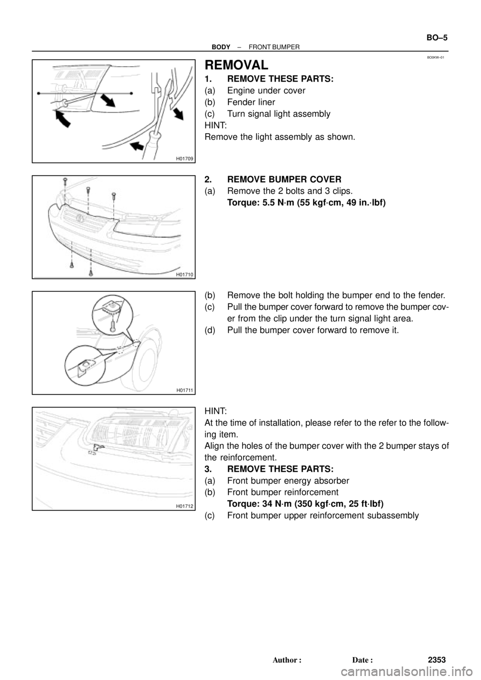
REMOVAL
1. REMOVE THESE PARTS:
(a) Engine under cover
(b) Fender liner
(c) Turn signal light assembly
HINT:
Remove the light assembly as shown.
2. REMOVE BUMPER COVER
(a) Remove the 2 bolts and 3 clips.
Torque: 5.5 N´m (55 kgf´cm, 49 in.´lbf)
(b) Remove the bolt holding the bumper end to the fender.
(c) Pull the bumper cover forward to remove the bumper cov-
er from the clip under the turn signal light area.
(d) Pull the bumper cover forward to remove it.
HINT:
At the time of installation, please refer to the refer to the follow-
ing item.
Align the holes of the bumper cover with the 2 bumper stays of
the reinforcement.
3. REMOVE THESE PARTS:
(a) Front bumper energy absorber
(b) Front bumper reinforcement
Torque: 34 N´m (350 kgf´cm, 25 ft´lbf)
(c) Front bumper upper reinforcement subassembly
Page 2012 of 4770
N10192
BO0M1±01
± BODYSLIDING ROOF (TMC Made)
BO±53
2401 Author�: Date�:
SLIDING ROOF (TMC Made)
ON±VEHICLE INSPECTION
INSPECT SLIDING ROOF GLASS ALIGNMENT
(a) Start the engine and check the operation time of the slid-
ing roof.
Operation time:
Approx. 6 secs.
(b) Check for abnormal noise or binding during operation.
(c) With the sliding roof fully closed, check for water leakage.
(d) Check for a difference in level between the sliding roof
weatherstrip and roof panel.
Except rear end:
0 ± 1.5 mm (0 ± 0.059 in.)
Rear end:
0 + 1.5 mm (0 + 0.059 in.)
0 ± 1.0 mm (0 ± 0.039 in.)
Page 2021 of 4770
H01814
BO0LU±01
H01815
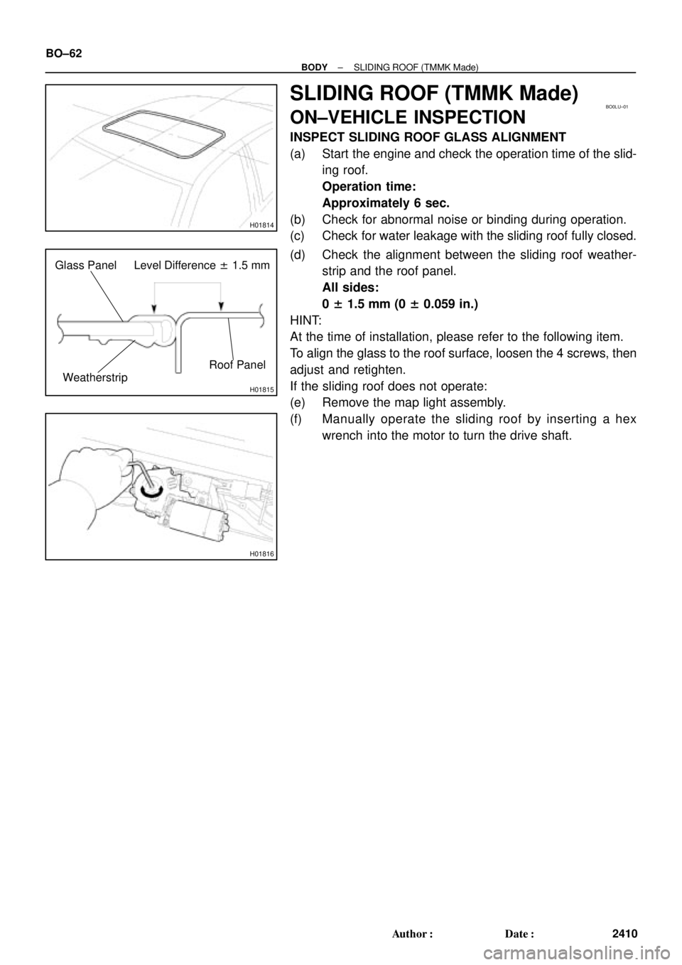
Glass Panel Level Difference ± 1.5 mm
Roof Panel
Weatherstrip
H01816
BO±62
± BODYSLIDING ROOF (TMMK Made)
2410 Author�: Date�:
SLIDING ROOF (TMMK Made)
ON±VEHICLE INSPECTION
INSPECT SLIDING ROOF GLASS ALIGNMENT
(a) Start the engine and check the operation time of the slid-
ing roof.
Operation time:
Approximately 6 sec.
(b) Check for abnormal noise or binding during operation.
(c) Check for water leakage with the sliding roof fully closed.
(d) Check the alignment between the sliding roof weather-
strip and the roof panel.
All sides:
0 ± 1.5 mm (0 ± 0.059 in.)
HINT:
At the time of installation, please refer to the following item.
To align the glass to the roof surface, loosen the 4 screws, then
adjust and retighten.
If the sliding roof does not operate:
(e) Remove the map light assembly.
(f) Manually operate the sliding roof by inserting a hex
wrench into the motor to turn the drive shaft.
Page 2097 of 4770

SymptomSuspect AreaSee page
Headlight does not light.
(Taillight is normal)1. Wire Harness±")
± BODY ELECTRICALBODY ELECTRICAL SYSTEM
BE±3
2223 Author�: Date�:
HEADLIGHT AND TAILLIGHT SYSTEM (CANADA)
SymptomSuspect AreaSee page
Headlight does not light.
(Taillight is normal)1. Wire Harness±
Headlight does not light.
(Taillight does not light up)1. Wire Harness±
Only one side light does not light.
1. Headlight Bulb
2. HEAD LO (LH, RH) Fuse (E/G Room R/B No.2)
3. Wire Harness±
±
±
ºLo±Beamº does not light.
1. Headlight Bulb
2. HEAD LO (LH, RH) Fuse (E/G Room R/B No.2)
3. Headlight Control Relay (E/G Room J/B No.2)
4. Integration Relay (I/P J/B No.1)
5. Light Control Switch
6. Wire Harness±
±
BE±24
BE±14
BE±24
±
ºHi±Beamº does not light.
1. Headlight Bulb
2. ECU±B Fuse (E/G Room J/B No.2)
3. HEAD HI (LH, RH) Fuse (E/G Room J/B No.2)
4. DRL Fuse (E/G Room R/B No.2)
5. Daytime Running Light Relay No.2
(E/G Room R/B No.2)
6. Daytime Running Light Relay No.3
(E/G Room R/B No.2)
7. Daytime Running Light Relay No.4
(E/G Room R/B No.2)
8. Daytime Running Light Relay (Main)
9. Headlight Dimmer Switch
10.Wire Harness±
±
±
±
±
BE±24
±
BE±24
±
BE±24
BE±24
BE±24
±
ºFlashº does not light.
1. Headlight Bulb
2. ECU±B Fuse (E/G Room J/B No.2)
3. HEAD HI (LH, RH) Fuse (E/G Room J/B No.2)
4. DRL Fuse (E/G Room R/B No.2)
5. Daytime Running Light Relay No.2
(E/G Room R/B No.2)
6. Daytime Running Light Relay No.3
(E/G Room R/B No.2)
7. Daytime Running Light Relay No.4
(E/G Room R/B No.2)
8. Daytime Running Light Relay (Main)
9. Headlight Dimmer Switch
10.Wire Harness±
±
±
±
±
BE±24
±
BE±24
±
BE±24
BE±24
BE±24
±
ºAuto Turn±off Systemº does not operate.
1. GAUGE Fuse (I/P J/B No.1)
2. DOME Fuse (E/G Room J/B No.2)
3. Integration Relay (I/P J/B No.2)
4. Door Courtesy Switch (Driver's)
5. Ignition Switch
6. Wire Harness±
±
BE±14
BE±24
BE±14
±
Headlight does not light with engine running and light control SW
OFF.
1. Headlight Bulb
2. ECU±B Fuse (E/G Room J/B No.2)
3. GAUGE Fuse (I/P J/B No.1)
4. HEAD HI (LH, RH) Fuse (E/G Room J/B No.2)
5. Daytime Running Light Relay (Main)
6. Wire Harness
7. Other Parts*±
±
±
±
BE±24
±
±
Page 2100 of 4770

BE±6
± BODY ELECTRICALBODY ELECTRICAL SYSTEM
2226 Author�: Date�:
Washer fluid does not operate.1. Washer Hose and Nozzle±
� In wiper switch HI position, the wiper blade is in contact with
the body.
� When the wiper switch is OFF, the wiper blade does not
retract or the retract position is wrong.1. *1Wiper Switch
2. Wire HarnessBE±40
±
COMBINATION METER
METER, GAUGES AND ILLUMINATION:
SymptomSuspect AreaSee page
Tachometer, Fuel Gauge and Engine Coolant Temperature Gauge
do not operate.1. GAUGE Fuse (I/P J/B No.1)
2. Meter Circuit Plate
3. Wire Harness±
BE±46
±
Speedometer does not operate.
1. No.1 Vehicle Speed Sensor
2. Meter Circuit Plate
3. Wire HarnessBE±47
BE±46
±
Tachometer does not operate.
1. Igniter (5S±FE)
(1MZ±FE)
2. Meter Circuit Plate
3. Wire HarnessIG±1
IG±1
BE±46
±
Fuel Gauge does not operate or abnormal operation.
1. Fuel Receiver Gauge
2. Fuel Sender Gauge
3. Meter Circuit Plate
4. Wire HarnessBE±47
BE±47
BE±46
±
Engine Coolant Temperature Gauge does not operate or abnormal
operation
1. Engine Coolant Temperature Receiver Gauge
2. Engine Coolant Temperature Sender Gauge
3. Meter Circuit Plate
4. Wire HarnessBE±47
BE±47
BE±46
±
All illumination lights do not light up.
1. TAIL Fuse (I/P J/B No.1)
2. Light Control Rheostat
3. Wire Harness±
BE±47
±
Brightness does not change even when rheostat turned.1. Bulb
2. Wire Harness±
±
Only one illumination light does not light up.1. Bulb
2. Wire Harness±
±
COMBINATION METER
WARNING LIGHTS:
SymptomSuspect AreaSee page
Warning lights do not light up. (Except Discharge, Open Door and
SRS)1. GAUGE Fuse (I/P J/B No.1)
2. Meter Circuit Plate
3. Wire Harness±
BE±46
±
Low Oil Pressure warning light does not light up.
1. Bulb
2. Low Oil Pressure Warning Switch
3. Meter Circuit Plate
4. Wire Harness±
BE±47
BE±46
±
Fuel Level warning light does not light up.
1. Bulb
2. Fuel Level Warning Switch
3. Meter Circuit Plate
4. Wire Harness±
BE±47
BE±46
±
ABS warning light does not light up.
1. Bulb
2. ABS ECU
3. Wire Harness±
IN±31
±
Page 2105 of 4770
BE0A0±03
Z19043
Engine Room Relay Block No.1
Engine Room Junction
Block No.2
Engine Room Relay Block No.2
Instrument Panel Junction Block No.1
Turn Signal Flasher
± BODY ELECTRICALPOWER SOURCE
BE±11
2231 Author�: Date�:
POWER SOURCE
LOCATION