Page 2219 of 4770

4. Remove the mast")
1. Insert master key in the key cylinder.
2. Depress and release the acceleration pedal 6 times.
3. Depress and release the brake pedal 7 times.
(Security indicator blinks)
4. Remove the master key.
(Security indicator blinks)
HINT:
When the key cannot be pulled out in the step 4, key code deletion is canceled.
(Security indicator is OFF) END
(Key code erasured)
Within 15 sec.
Within 20 sec.
Within 10 sec.
± BODY ELECTRICALENGINE IMMOBILISER SYSTEM
BE±125
2345 Author�: Date�:
4. ERASURE OF TRANSPONDER KEY CODE
There are 2 ways for erasure of transponder key code, one is depressing brake pedal and acceleration pedal
and the other is using TOYOTA hand±held tester.
NOTICE:
All other master and sub±key codes are deleted leaving the master key code to use the operation.
When using the key which was used before deleting, it is necessary to register the code again.
HINT:
�When any operation time described below is over, registration mode completes.
�When the next procedure is performed while the timer is working, the timer completes counting time,
then next timer starts.
(1) Depressing brake pedal and acceleration pedal:
Page 2220 of 4770
1. Insert master key in the key cylinder.
2. Require key code deletion from hand±held tester.
(Security indicator blinks)
3. Remove the master key.
HINT:
When the key cannot be pulled out in the step 3, key code deletion is canceled.
(Security indicator is OFF) END
(Key code erasured)
Within 120 sec.
Within 10 sec.
BE±126
± BODY ELECTRICALENGINE IMMOBILISER SYSTEM
2346 Author�: Date�:
(2) Using TOYOTA hand±held tester:
Page 2221 of 4770
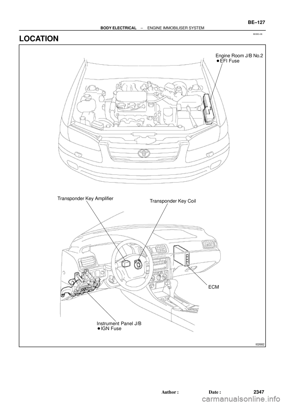
BE0B3±06
I02682
Engine Room J/B No.2
� EFI Fuse
Transponder Key Amplifier
Transponder Key Coil
ECM
� IGN Fuse Instrument Panel J/B
± BODY ELECTRICALENGINE IMMOBILISER SYSTEM
BE±127
2347 Author�: Date�:
LOCATION
Page 2222 of 4770
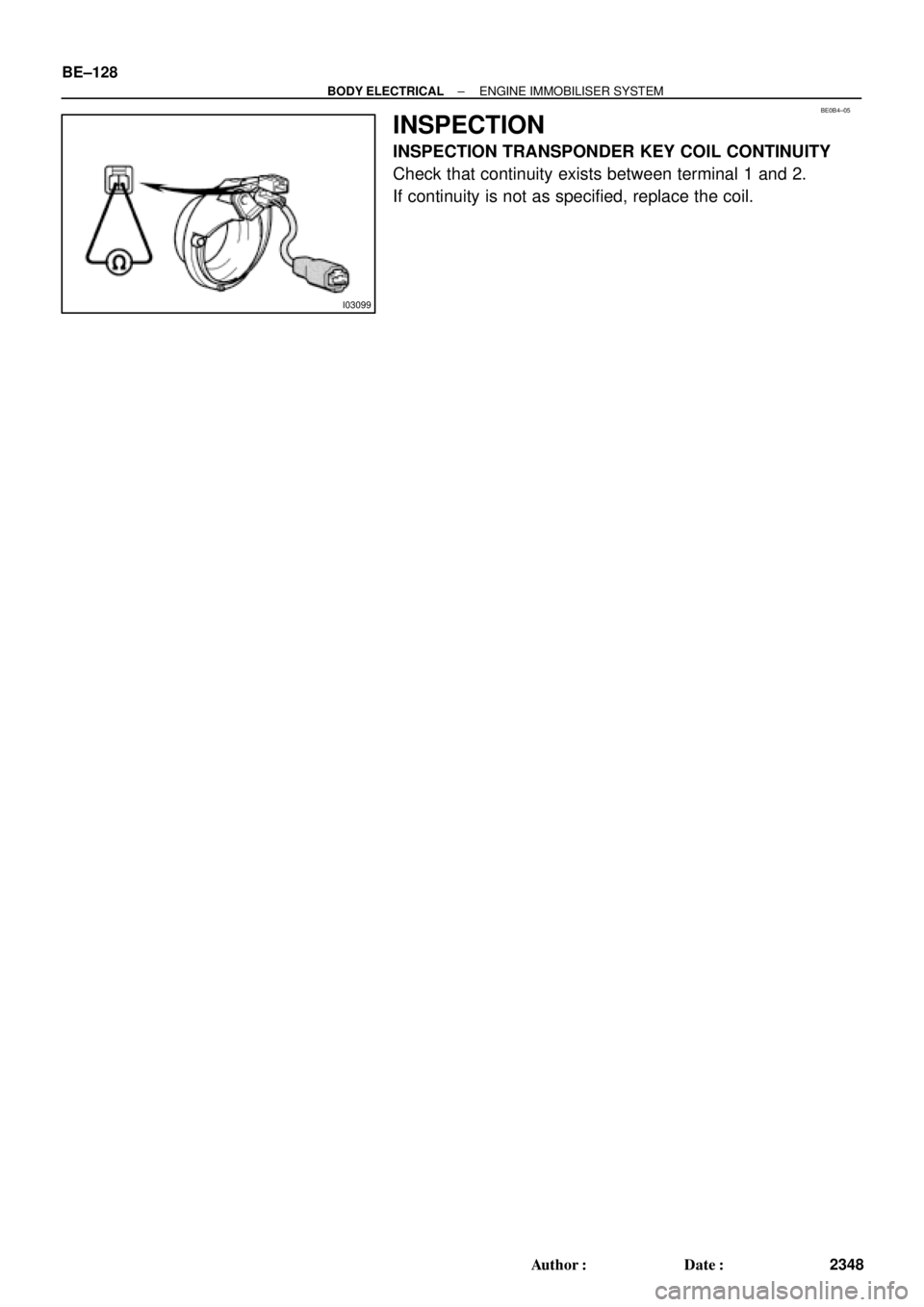
I03099
BE0B4±05
BE±128
± BODY ELECTRICALENGINE IMMOBILISER SYSTEM
2348 Author�: Date�:
INSPECTION
INSPECTION TRANSPONDER KEY COIL CONTINUITY
Check that continuity exists between terminal 1 and 2.
If continuity is not as specified, replace the coil.
Page 2227 of 4770

R00954
Stop Light
Switch
Push Rod
Pedal HeightBR0YH±01
R00935
Pedal Freeplay
± BRAKEBRAKE PEDAL
BR±5
2028 Author�: Date�:
BRAKE PEDAL
ON±VEHICLE INSPECTION
1. CHECK PEDAL HEIGHT
Pedal height from asphalt sheet:
152.0 ± 162.0 mm (5.984 ± 6.378 in.)
2. IF NECESSARY, ADJUST PEDAL HEIGHT
(a) Disconnect the connector from the stop light switch.
(b) Loosen the stop light switch lock nut and remove the stop
light switch.
(c) Loosen the push rod lock nut.
(d) Adjust the pedal height by turning the pedal push rod.
(e) Tighten the push rod lock nut.
Torque: 25 N´m (260 kgf´cm, 19 ft´lbf)
(f) Install the stop light switch and turn it until it lightly con-
tacts the pedal stopper.
(g) Push in the brake pedal 5±15 mm (0.20±0.59 in.), turn the
stop light switch to lock the nut in the position where the
stop light goes off.
(h) Connect the connector to the stop light switch.
(i) After installation, push in the brake pedal 5±15 mm
(0.20±0.59 in.), check that stop light lights up.
(j) Connect the connector to the stop light switch.
(k) After adjusting the pedal height, check the pedal freeplay.
3. CHECK PEDAL FREEPLAY
(a) Stop the engine and depress the brake pedal several
times until there is no more vacuum left in the booster.
(b) Push in the pedal by hand until the resistance begins to
be felt, then measure the distance.
Pedal freeplay: 1 ± 6 mm (0.04 ± 0.24 in.)
HINT:
The freeplay to the 1st resistance is due to the play between the
clevis and pin. This is magnified up to 1 ± 6 mm (0.04 ± 0.24 in.)
at the pedal.
If incorrect, check the stop light switch clearance.
If the clearance is OK, then troubleshoot the brake system.
Stop light switch clearance:
0.5 ± 2.4 mm (0.020 ± 0.094 in.)
Page 2228 of 4770
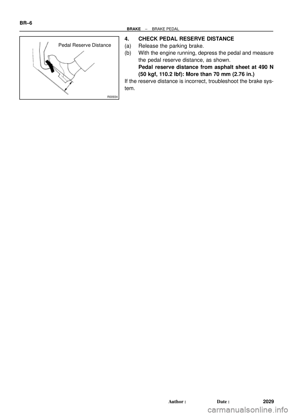
R00934
Pedal Reserve Distance BR±6
± BRAKEBRAKE PEDAL
2029 Author�: Date�:
4. CHECK PEDAL RESERVE DISTANCE
(a) Release the parking brake.
(b) With the engine running, depress the pedal and measure
the pedal reserve distance, as shown.
Pedal reserve distance from asphalt sheet at 490 N
(50 kgf, 110.2 lbf): More than 70 mm (2.76 in.)
If the reserve distance is incorrect, troubleshoot the brake sys-
tem.
Page 2239 of 4770
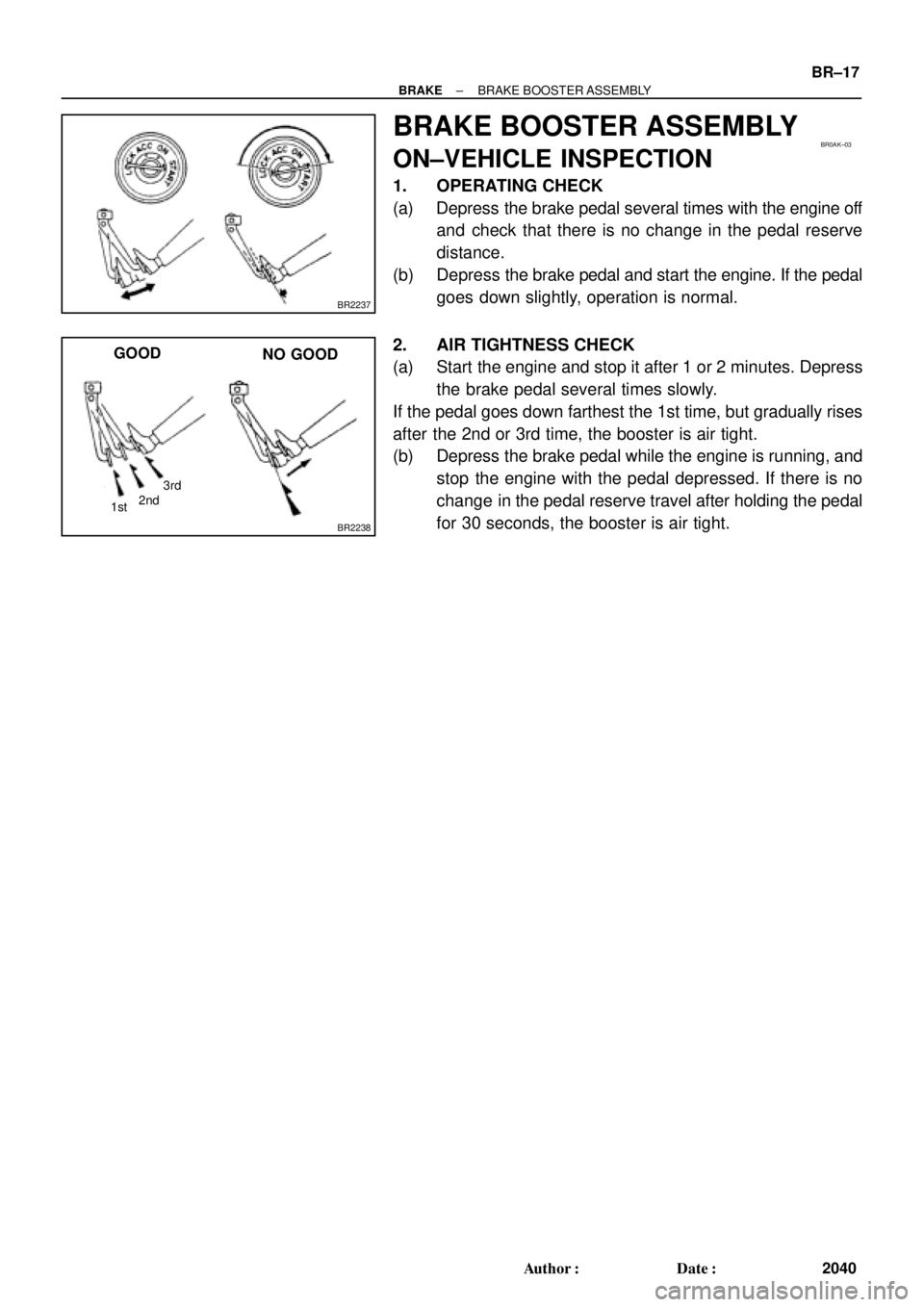
BR2237
BR0AK±03
BR2238
1st3rd
2nd
GOOD
NO GOOD
± BRAKEBRAKE BOOSTER ASSEMBLY
BR±17
2040 Author�: Date�:
BRAKE BOOSTER ASSEMBLY
ON±VEHICLE INSPECTION
1. OPERATING CHECK
(a) Depress the brake pedal several times with the engine off
and check that there is no change in the pedal reserve
distance.
(b) Depress the brake pedal and start the engine. If the pedal
goes down slightly, operation is normal.
2. AIR TIGHTNESS CHECK
(a) Start the engine and stop it after 1 or 2 minutes. Depress
the brake pedal several times slowly.
If the pedal goes down farthest the 1st time, but gradually rises
after the 2nd or 3rd time, the booster is air tight.
(b) Depress the brake pedal while the engine is running, and
stop the engine with the pedal depressed. If there is no
change in the pedal reserve travel after holding the pedal
for 30 seconds, the booster is air tight.
Page 2243 of 4770
BR0AO±03
F06983F07224
F07225
Anti±squeal Shim
Inner Anti±squeal Shim
Anti±squeal Spring
Pad Support Plate
Inner PadOuter Pad
1MZ±FE engine: 5S±FE engine:
Anti±squeal Shim
Inner Anti±squeal Shim
Pad Wear Indicator Plate
Outer Pad
Pad Support Plate
Inner Pad
Disc brake grease
N´m (kgf´cm, ft´lbf): Specified torque
34 (350, 25)
34 (350, 25)
± BRAKEFRONT BRAKE PAD
BR±21
2044 Author�: Date�:
FRONT BRAKE PAD
COMPONENTS

3. Remove the master key.
HINT:
When the key cannot be pulled out in")