Page 2273 of 4770

BR±51
2074 Author�: Date�:
(c) Place the ºSHEET Pº (SST) on the actuator checker.
SST SST 09990±00430
4. INSPECT BRAKE ACTUATOR")
F07214
W03269
W03270
W03268
W03271
± BRAKEABS ACTUATOR (DENSO Made)
BR±51
2074 Author�: Date�:
(c) Place the ºSHEET Pº (SST) on the actuator checker.
SST SST 09990±00430
4. INSPECT BRAKE ACTUATOR OPERATION
(a) Start the engine, and run it at idle.
(b) Turn the selector switch of the actuator checker to
ºFRONT LHº position.
(c) Push and hold in the MOTOR switch for a few seconds.
(d) Depress the brake pedal and hold it until step (g) is com-
pleted.
(e) Push the MAIN push switch, and check that the brake
pedal does not go down.
NOTICE:
Do not keep the MAIN push switch pushed down for more
than 10 seconds.
(f) Release the switch, and check that the pedal goes down.
(g) Push and hold in the MOTOR switch for a few seconds,
and check that the pedal returns.
(h) Release the brake pedal.
(i) Push and hold in the MOTOR switch for a few seconds.
(j) Depress the brake pedal and hold it for about 15 seconds.
As you hold the pedal down, push the MOTOR switch for
a few seconds. Check that the brake pedal does not pul-
sate.
(k) Release the brake pedal.
(l) Turn the selector switch to ºREAR RHº position.
(m) Repeat (c) to (j), checking the actuator operation similarly.
(n) Similarly, inspect ºREAR LHº and ºFRONT RHº position.
HINT:
When inspecting ºFRONT RHº position, push the FRONT RH
switch instead of the MAIN push switch, and you can inspect in
any selector switch position.
Page 2274 of 4770
W03267
BR±52
± BRAKEABS ACTUATOR (DENSO Made)
2075 Author�: Date�:
(o) Push and hold in the MOTOR switch for a few seconds.
(p) Stop the engine.
5. DISCONNECT ACTUATOR CHECKER (SST) FROM
ACTUATOR
Remove the ºSHEET Pº (SST) and disconnect the actuator
checker (SST) and sub±wire harness (SST) from the actuator.
SST 09990±00150, 09990±00250, 09990±00300,
09990±00360, 09990±00430
6. CONNECT CONNECTORS
Connect the 2 connectors to the actuator.
7. CLEAR DTC (See page DI±493)
Page 2284 of 4770
 Place the ºSHEET Aº (SST) on the actuator checker.
SST 09990±00163
4. INSPECT BRAKE ACTUATOR OPERATION")
BR1811
R00324
R00325
R00326
BR1813
BR±62
± BRAKEABS & TRAC ACTUATOR
2085 Author�: Date�:
(c) Place the ºSHEET Aº (SST) on the actuator checker.
SST 09990±00163
4. INSPECT BRAKE ACTUATOR OPERATION
(a) Start the engine, and run it at idle.
(b) Turn the selector switch of the actuator checker to
ºFRONT RHº position.
(c) Push and hold in the MOTOR switch for a few seconds.
(d) Depress the brake pedal and hold it until step (g) is com-
pleted.
(e) Push the POWER SWITCH, and check that the brake
pedal does not go down.
NOTICE:
Do not keep the POWER SWITCH pushed down for more
than 10 seconds.
(f) Release the switch, and check that the pedal goes down.
(g) Push and hold in the MOTOR switch for a few seconds,
and check that the pedal returns.
(h) Release the brake pedal.
(i) Push and hold in the MOTOR switch for a few seconds.
(j) Depress the brake pedal and hold it for about 15 seconds.
As you hold the pedal down, push the MOTOR switch for
a few seconds. Check that the brake pedal does not pul-
sate.
(k) Release the brake pedal.
(l) Turn the selector switch to ºFRONT LHº position.
(m) Repeat (c) to (j), checking the actuator operation similarly.
(n) Similarly, inspect ºREAR RHº and ºREAR LHº position.
HINT:
When inspecting ºREAR LHº position, push the REAR LH
switch instead of the POWER SWITCH, and you can inspect in
any selector switch position.
Page 2285 of 4770
BR1811
± BRAKEABS & TRAC ACTUATOR
BR±63
2086 Author�: Date�:
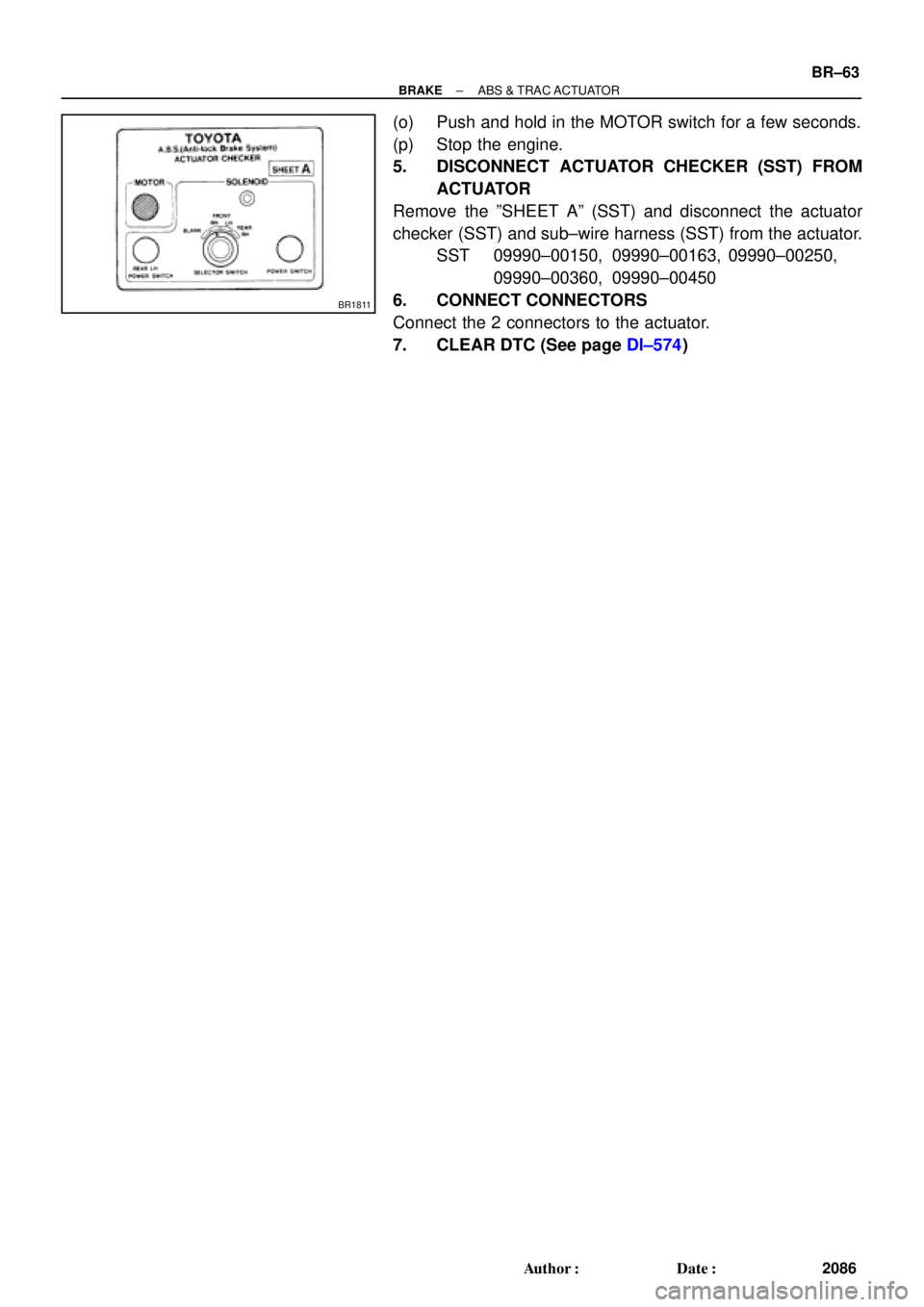
(o) Push and hold in the MOTOR switch for a few seconds.
(p) Stop the engine.
5. DISCONNECT ACTUATOR CHECKER (SST) FROM
ACTUATOR
Remove the ºSHEET Aº (SST) and disconnect the actuator
checker (SST) and sub±wire harness (SST) from the actuator.
SST 09990±00150, 09990±00163, 09990±00250,
09990±00360, 09990±00450
6. CONNECT CONNECTORS
Connect the 2 connectors to the actuator.
7. CLEAR DTC (See page DI±574)
Page 2295 of 4770
CHARGING SYSTEM
CH±1
1748 Author�: Date�:
CHARGING SYSTEM
ON±VEHICLE INSPECTION
CAUTI")
CH02U±01
Z11577
Except Maintenance±Free Battery
Z11556
Maintenance±Free Battery
Voltmeter
± CHARGING (5S±FE)CHARGING SYSTEM
CH±1
1748 Author�: Date�:
CHARGING SYSTEM
ON±VEHICLE INSPECTION
CAUTION:
�Check that the battery cables are connected to the
correct terminals.
�Disconnect the battery cables when the battery is giv-
en a quick charge.
�Do not perform tests with a high voltage insulation re-
sistance tester.
�Never disconnect the battery while the engine is run-
ning.
1. CHECK BATTERY ELECTROLYTE LEVEL
Check the electrolyte quantity of each cell.
Maintenance±Free Battery:
If under the lower level, replace the battery (or add distilled wa-
ter if possible). Check the charging system.
Except Maintenance±Free Battery:
If under the lower level, add distilled water.
2. Except Maintenance±Free Battery:
CHECK BATTERY SPECIFIC GRAVITY
Check the specific gravity of each cell.
Standard specific gravity:
1.25 ± 1.29 at 20°C (68°F)
If the specific gravity is less than specification, charge the bat-
tery.
3. Maintenance±Free Battery:
CHECK BATTERY VOLTAGE
(a) After having driven the vehicle and in the case that 20
minutes have not passed after having stopped the en-
gine, turn the ignition switch ON and turn on the electrical
system (headlight, blower motor, rear defogger etc.) for
60 seconds to remove the surface charge.
(b) Turn the ignition switch OFF and turn off the electrical sys-
tems.
(c) Measure the battery voltage between the negative (±)
and positive (+) terminals of the battery.
Standard voltage: 12.5 ± 12.9 V at 20°C (68°F)
If the voltage is less than specification, charge the battery.
Page 2296 of 4770

Z18811
Maintenance±Free Battery
Type A
Type B
Blue White Red
OK Charging
NecessaryInsufficient
Water
GREEN EYE DARK EYECLEAR EYE or
CHARGED DISCHARGED ADD WATERLIGHT YELLOW
Z00015
Z00038
DENSOBorroughs
CH0086
CORRECTWRONG CH±2
± CHARGING (5S±FE)CHARGING SYSTEM
1749 Author�: Date�:
HINT:
Check the indicator as shown in the illustration.
4. CHECK BATTERY TERMINALS, FUSIBLE LINK AND
FUSES
(a) Check that the battery terminals are not loose or cor-
roded.
If the terminals are corroded, clean the terminals.
(b) Check the fusible link, H±fuses, M±fuse and fuses for
continuity.
5. INSPECT DRIVE BELTS
(a) Visually check the drive belt for excessive wear, frayed
cords etc.
If any defect has been found, replace the drive belt.
HINT:
Cracks on the rib side of a drive belt are considered acceptable.
If the drive belt has chunks missing from the ribs, it should be
replaced.
(b) Using a belt tension gauge, measure the belt tension.
Belt tension gauge:
DENSO BTG±20 (95506±00020)
Borroughs No. BT±33±73F
Drive belt tension:
w/ A/C New belt
Used belt165 ± 25 lbf
110 ± 10 lbf
w/o A/C New belt
Used belt125 ± 25 lbf
95 ± 20 lbf
If the belt tension is not as specified, adjust it.
HINT:
�ºNew beltº refers to a belt which has been used less than
5 minutes on a running engine.
�ºUsed beltº refers to a belt which has been used on a run-
ning engine for 5 minutes or more.
�After installing a belt, check that it fits properly in the
ribbed grooves.
�Check with your hand to confirm that the belt has not
slipped out of the groove on the bottom of the pulley.
Page 2297 of 4770
CHARGING SYSTEM
CH±3
1750 Author�: Date�: �
After installing a new belt, run the engine for about 5 min")
Z03473
BatteryVoltmeter
Generator Ammeter
Disconnect Wire
from Terminal B
B
± CHARGING (5S±FE)CHARGING SYSTEM
CH±3
1750 Author�: Date�: �
After installing a new belt, run the engine for about 5 min-
utes and recheck the belt tension.
6. VISUALLY CHECK GENERATOR WIRING AND
LISTEN FOR ABNORMAL NOISES
(a) Check that the wiring is in good condition.
(b) Check that there is no abnormal noise from the generator
while the engine is running.
7. CHECK CHARGE WARNING LIGHT CIRCUIT
(a) Warm up the engine and then turn it off.
(b) Turn off all accessories.
(c) Turn the ignition switch ºONº. Check that the charge warn-
ing light is lit.
(d) Start the engine. Check that the light goes off.
If the light does not go off as specified, troubleshoot the charge
light circuit.
8. INSPECT CHARGING CIRCUIT WITHOUT LOAD
HINT:
If a battery/generator tester is available, connect the tester to
the charging circuit as per manufacturer's instructions.
(a) If a tester is not available, connect a voltmeter and amme-
ter to the charging circuit as follows:
(1) Disconnect the wire from terminal B of the genera-
tor, and connect it to the negative (±) tester probe
of the ammeter.
(2) Connect the positive (+) tester probe of the amme-
ter to terminal B of the generator.
(3) Connect the positive (+) tester probe of the voltme-
ter to terminal B of the generator.
(4) Ground the negative (±) tester probe of the voltme-
ter.
(b) Check the charging circuit as follows:
With the engine running from idling to 2,000 rpm, check
the reading on the ammeter and voltmeter.
Standard amperage: 10 A or less
Standard voltage: 13.5 ± 15.1 V
If the voltmeter reading is more than standard voltage, replace
the voltage regulator.
Page 2298 of 4770
P14433
Terminal F CH±4
± CHARGING (5S±FE)CHARGING SYSTEM
1751 Author�: Date�:
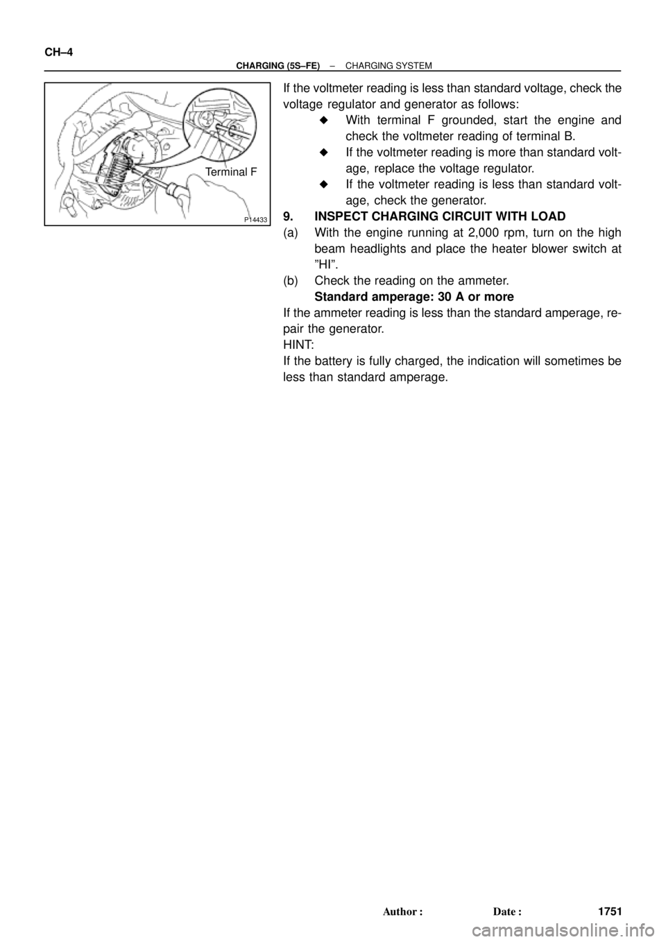
If the voltmeter reading is less than standard voltage, check the
voltage regulator and generator as follows:
�With terminal F grounded, start the engine and
check the voltmeter reading of terminal B.
�If the voltmeter reading is more than standard volt-
age, replace the voltage regulator.
�If the voltmeter reading is less than standard volt-
age, check the generator.
9. INSPECT CHARGING CIRCUIT WITH LOAD
(a) With the engine running at 2,000 rpm, turn on the high
beam headlights and place the heater blower switch at
ºHIº.
(b) Check the reading on the ammeter.
Standard amperage: 30 A or more
If the ammeter reading is less than the standard amperage, re-
pair the generator.
HINT:
If the battery is fully charged, the indication will sometimes be
less than standard amperage.