Page 2348 of 4770
Q10091
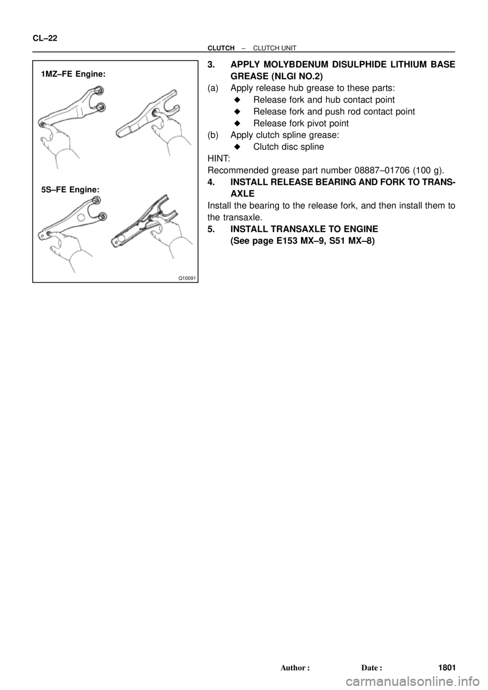
1MZ±FE Engine:
5S±FE Engine: CL±22
± CLUTCHCLUTCH UNIT
1801 Author�: Date�:
3. APPLY MOLYBDENUM DISULPHIDE LITHIUM BASE
GREASE (NLGI NO.2)
(a) Apply release hub grease to these parts:
�Release fork and hub contact point
�Release fork and push rod contact point
�Release fork pivot point
(b) Apply clutch spline grease:
�Clutch disc spline
HINT:
Recommended grease part number 08887±01706 (100 g).
4. INSTALL RELEASE BEARING AND FORK TO TRANS-
AXLE
Install the bearing to the release fork, and then install them to
the transaxle.
5. INSTALL TRANSAXLE TO ENGINE
(See page E153 MX±9, S51 MX±8)
Page 2349 of 4770
CO066±03
± COOLING (5S±FE)COOLANT
CO±1
1575 Author�: Date�:
COOLANT
INSPECTION
HINT:
Check the coolant level when the engine is cold.
1. CHECK ENGINE COOLANT LEVEL AT RADIATOR RESERVOIR
The engine coolant level should be between the ºLOWº and ºFULLº lines.
If low, check for leaks and add ºToyota Long Life Coolantº or equivalent up to the ºFULLº line.
2. CHECK ENGINE COOLANT QUALITY
(a) Remove the radiator cap.
CAUTION:
To avoid the danger of being burned, do not remove the radiator cap while the engine and radiator
are still hot, as fluid and steam can be blown out under pressure.
(b) There should not be any excessive deposits of rust or scale around the radiator cap or radiator filler
hole, and the coolant should be free from oil.
If excessively dirty, replace the coolant.
(c) Reinstall the radiator cap.
Page 2350 of 4770
COOLANT
1576 Author�: Date�:
REPLACEMENT
1. DRAIN ENGINE COOLANT
(a) Remove the radiator cap.
CAUTION:
To avoid the dang")
CO067±03
Z18990
Radiator Drain Plug
Engine Drain Plug CO±2
± COOLING (5S±FE)COOLANT
1576 Author�: Date�:
REPLACEMENT
1. DRAIN ENGINE COOLANT
(a) Remove the radiator cap.
CAUTION:
To avoid the danger of being burned, do not remove the ra-
diator cap while the engine and radiator are still hot, as fluid
and steam can be blown out under pressure.
(b) Loosen the radiator drain plug (on the right side of the ra-
diator lower tank) and engine drain plug (on the left rear
of the cylinder block), and drain the coolant.
(c) Close the drain plugs.
Torque: 25 N´m (250 kgf´cm, 18 ft´lbf) for engine
2. FILL ENGINE COOLANT
(a) Slowly fill the system with coolant.
�Use of improper coolants may damage engine cool-
ing system.
�Use ºToyota Long Life Coolantº or equivalent and
mix it with plan water according to the manufactur-
er's directions.
�Using of coolant which includes more than 50 %
(freezing protection down to ±35°C (±31°F) or 60 %
(freezing protection down to ±50°C (±58°F)) of eth-
ylene±glycol is recommended but not more than 70
%.
NOTICE:
�Do not use an alcohol type coolant or plain water
alone.
�The coolant should be mixed with plain water (prefer-
ably demineralized water or distilled water).
Capacity:
w/ Oil cooler6.9 litters (7.3 US qts, 6.1 lmp. qts)
w/o Oil cooler6.2 litters (6.5 US qts, 5.4 lmp. qts)
(b) Install the radiator cap.
(c) Start the engine, and bleed the cooling system.
(d) Refill the radiator reservoir with coolant until it reaches the
ºFULLº line.
3. CHECK FOR COOLANT LEAKS
Page 2351 of 4770
CO068±03
S05543
Engine Moving Control Rod
No.2 RH Engine Mounting Bracket
Generator Drive Belt
w/ Oil Cooler
A/C Compressor
Connector
A/C Compressor
Cylinder Block Insulator
N´m (kgf´cm, ft´lbf)RH Front Fender Apron SealPS Pump Drive BeltGround Strap Connector
: Specified torque
64 (650, 47)
64 (650, 47)
52 (530, 38)
± COOLING (5S±FE)WATER PUMP
CO±3
1577 Author�: Date�:
WATER PUMP
COMPONENTS
Page 2353 of 4770
CO069±04
S05599
S05924
S05963
1
2
3
± COOLING (5S±FE)WATER PUMP
CO±5
1579 Author�: Date�:
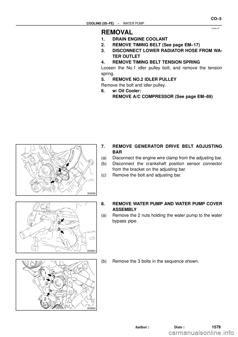
REMOVAL
1. DRAIN ENGINE COOLANT
2. REMOVE TIMING BELT (See page EM±17)
3. DISCONNECT LOWER RADIATOR HOSE FROM WA-
TER OUTLET
4. REMOVE TIMING BELT TENSION SPRING
Loosen the No.1 idler pulley bolt, and remove the tension
spring.
5. REMOVE NO.2 IDLER PULLEY
Remove the bolt and idler pulley.
6. w/ Oil Cooler:
REMOVE A/C COMPRESSOR (See page EM±69)
7. REMOVE GENERATOR DRIVE BELT ADJUSTING
BAR
(a) Disconnect the engine wire clamp from the adjusting bar.
(b) Disconnect the crankshaft position sensor connector
from the bracket on the adjusting bar.
(c) Remove the bolt and adjusting bar.
8. REMOVE WATER PUMP AND WATER PUMP COVER
ASSEMBLY
(a) Remove the 2 nuts holding the water pump to the water
bypass pipe.
(b) Remove the 3 bolts in the sequence shown.
Page 2355 of 4770
CO06A±03
S01486
Turn
Air Hole
± COOLING (5S±FE)WATER PUMP
CO±7
1581 Author�: Date�:
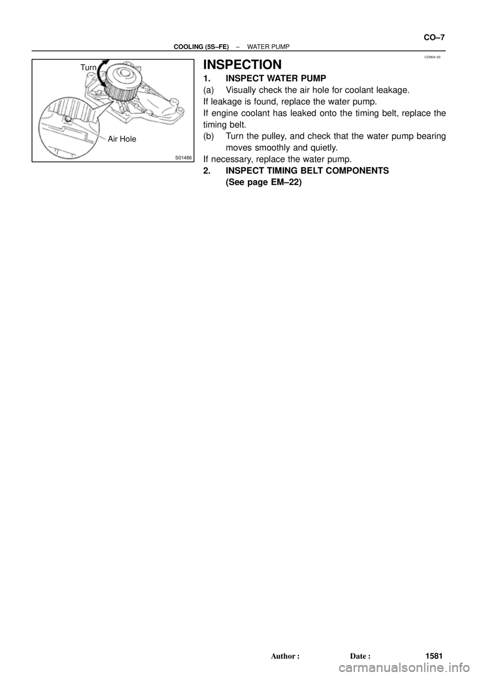
INSPECTION
1. INSPECT WATER PUMP
(a) Visually check the air hole for coolant leakage.
If leakage is found, replace the water pump.
If engine coolant has leaked onto the timing belt, replace the
timing belt.
(b) Turn the pulley, and check that the water pump bearing
moves smoothly and quietly.
If necessary, replace the water pump.
2. INSPECT TIMING BELT COMPONENTS
(See page EM±22)
Page 2356 of 4770
WATER PUMP
1582 Author�: Date�:
INSTALLATION
1. INSTALL WATER PUMP TO WATER PUMP COVER
Install a new gasket and the")
CO06B±03
N00918
S06015
Connect
Z19283
1
3
2
S05924
S05599
CO±8
± COOLING (5S±FE)WATER PUMP
1582 Author�: Date�:
INSTALLATION
1. INSTALL WATER PUMP TO WATER PUMP COVER
Install a new gasket and the water pump with the 3 bolts.
Torque: 8.8 N´m (90 kgf´cm, 78 in.´lbf)
2. INSTALL WATER PUMP AND WATER PUMP COVER
ASSEMBLY
(a) Install new O±ring and gasket to water pump cover.
(b) Install a new O±ring to the water bypass pipe.
(c) Apply soapy water to the O±ring on the water bypass
pipe.
(d) Connect the water pump cover to the water bypass pipe.
Do not install the nuts yet.
(e) Install the water pump with the 3 bolts. Tighten the bolts
in the sequence shown.
Torque: 8.8 N´m (90 kgf´cm, 78 in.´lbf)
(f) Install the 2 nuts holding the water pump cover to the wa-
ter bypass pipe.
Torque: 9.3 N´m (95 kgf´cm, 82 in.´lbf)
3. INSTALL GENERATOR DRIVE BELT ADJUSTING BAR
(a) Install the adjusting bar with the bolt.
Torque: 22 N´m (224 kgf´cm, 16 ft´lbf)
(b) Install the engine wire clamp to the adjusting bar.
(c) Install the crankshaft position sensor connector to the
bracket on the adjusting bar.
4. w/ Oil Cooler:
INSTALL A/C COMPRESSOR (See page EM±75)
5. INSTALL NO.2 IDLER PULLEY (See page EM±23)
Page 2357 of 4770
± COOLING (5S±FE)WATER PUMP
CO±9
1583 Author�: Date�:
6. INSTALL TIMING BELT TENSION SPRING
(See page EM±23)
7. CONNECT LOWER RADIATOR HOSE TO WATER IN-
LET
8. INSTALL TIMING BELT (See page EM±23)
9. FILL WITH ENGINE COOLANT
10. START ENGINE AND CHECK FOR COOLANT LEAKS

RH")