2000 DODGE NEON diagram
[x] Cancel search: diagramPage 362 of 1285
REMOVAL
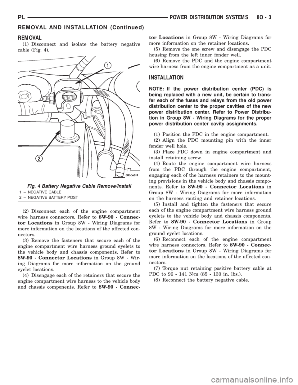
(1) Disconnect and isolate the battery negative
cable (Fig. 4).
(2) Disconnect each of the engine compartment
wire harness connectors. Refer to8W-90 - Connec-
tor Locationsin Group 8W - Wiring Diagrams for
more information on the locations of the affected con-
nectors.
(3) Remove the fasteners that secure each of the
engine compartment wire harness ground eyelets to
the vehicle body and chassis components. Refer to
8W-90 - Connector Locationsin Group 8W - Wir-
ing Diagrams for more information on the ground
eyelet locations.
(4) Disengage each of the retainers that secure the
engine compartment wire harness to the vehicle body
and chassis components. Refer to8W-90 - Connec-tor Locationsin Group 8W - Wiring Diagrams for
more information on the retainer locations.
(5) Remove the one screw and disengage the PDC
housing from the left inner fender well.
(6) Remove the PDC and the engine compartment
wire harness from the engine compartment as a unit.
INSTALLATION
NOTE: If the power distribution center (PDC) is
being replaced with a new unit, be certain to trans-
fer each of the fuses and relays from the old power
distribution center to the proper cavities of the new
power distribution center. Refer to Power Distribu-
tion in Group 8W - Wiring Diagrams for the proper
power distribution center cavity assignments.
(1) Position the PDC in the engine compartment.
(2) Align the PDC mounting pin with the inner
fender well hole.
(3) Place PDC down in engine compartment and
install retaining screw.
(4) Route the engine compartment wire harness
from the PDC through the engine compartment,
engaging each of the harness retainers to the mount-
ing provisions in the vehicle body and chassis compo-
nents. Refer to8W-90 - Connector Locationsin
Group 8W - Wiring Diagrams for more information
on the harness routing and retainer locations.
(5) Install and tighten the fasteners that secure
each of the engine compartment wire harness ground
eyelets to the vehicle body and chassis components.
Refer to8W-90 - Connector Locationsin Group
8W - Wiring Diagrams for more information on the
ground eyelet locations.
(6) Reconnect each of the engine compartment
wire harness connectors. Refer to8W-90 - Connec-
tor Locationsin Group 8W - Wiring Diagrams for
more information on the locations of the affected con-
nectors.
(7) Torque nut retaining positive battery cable at
PDC to 96 - 141 Nzm (85 - 130 in. lbs.).
(8) Reconnect the battery negative cable.
Fig. 4 Battery Negative Cable Remove/Install
1 ± NEGATIVE CABLE
2 ± NEGATIVE BATTERY POST
PLPOWER DISTRIBUTION SYSTEMS 8O - 3
REMOVAL AND INSTALLATION (Continued)
Page 365 of 1285
first turn) will cause all vehicle doors to unlock elec-
trically. When this feature is disabled, all vehicle
doors will be unlocked electrically upon the first turn
of a key cylinder to the UNLOCK position. The vehi-
cle is locked electrically by turning the key cylinder
to the LOCK position once, regardless of the state of
the double activation unlock feature.
POWER DOOR LOCKS
The Remote Keyless Entry (RKE) Module actuates
the power door lock relays when a door lock switch is
activated. If the door lock switch is pressed for longer
than eight consecutive seconds, the RKE module will
de-energize the door lock motors.
The system includes the rolling door locking fea-
ture. The vehicle is shipped with the system enabled.
When the system is disabled the door locks will work
by use of the door lock switches and the Remote Key-
less Entry system only. When the rolling door lock
system is enabled, the RKE module will automati-
cally lock all the vehicle doors when all of the follow-
ing conditions are met:
²All doors are closed
²The vehicle speed exceeds 15 +/- 1 mph.
²The throttle position sensor tip-in is greater
than 10 +/- 2 degrees.
The RKE module will automatically re-lock all
doors if the above conditions are met and if any of
the doors become ajar and then closed again.
The enabling/disabling of the rolling door lock fea-
ture is customer programmable, as well as program-
mable with the DRB IIItscan tool.
The power lock motors are also equipped with a
thermal protection system which prevents the motors
from burning out. The motors may chatter if they are
continuously activated.
CHILD PROTECTION LOCKS
The child protection locks are on the rear doors
only. The lock, when engaged, will disable the inside
door handle from opening the door. The lock is part
of the latch/lock assembly. The lock is engaged by
moving a lever that is located on the rearward inside
edge of the door.
DOOR LOCK INHIBIT
With the key in the ignition switch and the driver
door open, the Remote Keyless Entry (RKE) Modulewill ignore the command to lock the power door locks
via the interior driver door lock switch. Once the key
is removed, or the driver door is closed, the RKE
module will allow the power door locks to lock via the
interior door lock switches.
DIAGNOSIS AND TESTING
DOOR LOCK MOTOR
(1) Make certain battery is in normal condition
and fuses powering the RKE module aren't blown
before circuits are tested.
(2) To determine which motor is faulty, check each
individual door for electrical lock and unlock or dis-
connect the motor connectors one at a time, while
operating the door lock switch.
(3) In the event that none of the motors work, the
problem maybe caused by a shorted motor, a bad
switch or a bad relay internal to the RKE module.
Disconnecting a defective motor will allow the others
to work.
(4) To test an individual door lock motor, discon-
nect the electrical connector from the motor.
(5) To lock the door, connect a 12 volt power source
to one pin of the lock motor and a ground wire to the
other pin.
(6) To unlock the door, reverse the wire connec-
tions at the motor pin terminals.
(7) If these results are NOT obtained, replace the
motor.
DOOR LOCK SWITCH
(1) Remove the switch from its mounting location,
and disconnect from vehicle wiring harness. Refer to
Door Lock Switch Removal and Installation in this
section.
(2) Using an ohmmeter, refer to Door Lock Switch
Resistance Test table to determine if switch resis-
tance is correct in the Lock and Unlock switch posi-
tions. Refer to Group 8W-Wiring Diagrams for
harness connector pin-outs.
DOOR LOCK SWITCH RESISTANCE
SWITCH POSITION CONTINUITY BETWEEN RESISTANCE VALUE
LOCK 2 AND 3 1000V
UNLOCK 2 AND 3 249V
8P - 2 POWER LOCK SYSTEMSPL
DESCRIPTION AND OPERATION (Continued)
Page 368 of 1285
NOTE: The dealer must remove the module from
ªShip Modeº and place the RKE Module into either
the ªDealer Lotº storage or ªCustomer Usageº
modes of operation after receiving the vehicle from
the assembly plant. Refer to Group 8Q-Vehicle
Theft/Security Systems, Switching Operating
Modes/Configuring a New Module under Service
Procedures.
REMOTE KEYLESS ENTRY SYSTEM
The system allows locking and unlock of vehicle
door(s) and deck lid by remote control using a hand
held radio frequency (RF) transmitter. The vehicle
speed must be less than five miles per hour before
the deck lid can be unlatched with the transmitter.
The receiver may receive signals from four transmit-
ters. Each transmitter has its own code and the code
has been stored in memory. If the transmitter is
replaced or other transmitters are added, the code for
each unit must be learned.
REMOTE KEYLESS ENTRY TRANSMITTER
The transmitter has four buttons for operation
(Fig. 1). They are LOCK, UNLOCK, DECK LID
RELEASE, and PANIC.
²The UNLOCK button will unlock the driver door
and enable illuminated entry. Pushing and releasing
the button once will unlock the driver door. Pushing
and releasing the button two times within a five sec-
ond period will unlock all doors (double unlock acti-
vation enabled).
²Upon pressing the LOCK button, the horn will
sound a short chirp (if enabled) and flash the park
lamps to notify that the all door lock signal was
received and acted upon. Illuminated entry is can-
celled and the interior lamps are faded to off.
²Pushing and releasing the DECK LID
RELEASE button twice within a five second period
will actuate the decklid release solenoid, causing the
deck lid to be slightly ajar. If so desired, the decklid
may be set to release after one button push by the
dealer. For procedures on programming with the
DRB IIItscan tool, refer to the proper Body Diagnos-
tic Procedures Manual.
²Pushing the PANIC button will cause the panic
alarm to sound for three minutes, until the panic
button is pressed a second time, or until the vehicle
reaches a speed of 15 mph.
HORN CHIRP TOGGLE
Once the transmitters have been programmed, the
horn chirp can be enabled/disabled by sending the
horn chirp toggle operation code to the RKE Module.
This can be done using a DRB IIItscan tool or by
the customer. The horn chirp will enter the oppositestate of its current programmed state by receiving
this operation code. The RKE module is responsible
for keeping track of the horn chirp status.
DIAGNOSIS AND TESTING
REMOTE KEYLESS ENTRY MODULE
For procedures on diagnosing and testing the RKE
Module's RKE functions, refer to the proper Body
Diagnostic Procedures Manual.
DECKLID RELEASE SOLENOID
(1) Confirm operation of RKE transmitter(s) by
actuating Lock and Unlock functions.
(2) Confirm lead is connected to deck lid release
solenoid.
(3) Unplug lead, and use an ohmmeter to verify
continuity of connection between pin 2 of the harness
connector and ground. Refer to Group 8W-Wiring
Diagrams for Connector Pin-Outs.
(4) Connect test light to pin 1 of the harness con-
nector and actuate decklid release button on trans-
mitter. Refer to Group 8W-Wiring Diagrams for
Connector Pin-Outs.
(5) If test light comes on, the wiring circuit
between the RKE module and the solenoid is func-
tional, and the decklid solenoid should be replaced.
(6) If test light does not come on, refer to the
proper Body Diagnostic Procedures Manual for fur-
ther troubleshooting information.
SERVICE PROCEDURES
HORN CHIRP TOGGLE
The toggling of the horn chirp (between enabled
and disabled) can be performed with the use of the
DRB IIItscan tool or by the customer.
DRB lllTPROGRAMMING
When using the DRB IIItscan tool, select:
(1) ªTheft Alarmº
(2) ªVTSSº
(3) ªMiscellaneousº
and then the desired function.
CUSTOMER PROGRAMMING
Using a transmitter programmed to the RKE Mod-
ule, the status of the horn chirp may be toggled by
the customer.
NOTE: The RKE Module is responsible for keeping
track of the horn chirp status; thus this procedure
does not need to be repeated for each transmitter
programmed to the system.
PLPOWER LOCK SYSTEMS 8P - 5
DESCRIPTION AND OPERATION (Continued)
Page 375 of 1285
memory to determine whether a valid key is in the
ignition lock cylinder.
The Sentry Key transponder cannot be repaired
and, if faulty or damaged, it must be replaced.
SENTRY KEY IMMOBILIZER SYSTEM
INDICATOR LAMP
The Sentry Key Immobilizer System (SKIS) uses
the Vehicle Theft Security System (VTSS) indicator
LED to give an indication when the SKIS is faulty or
when the vehicle has been immobilized due to the
use of an invalid ignition key. The LED is controlled
by the instrument cluster circuitry based upon mes-
sages received from the Sentry Key Immobilizer
Module (SKIM) through the Body Control Module
(BCM) on the Programmable Communication Inter-
face (PCI) bus.
The SKIM sends messages to the instrument clus-
ter, via the BCM, to turn the LED on for about three
seconds when the ignition switch is turned to the ON
position as a bulb test. After completion of the bulb
test, the SKIM sends PCI bus messages to keep the
LED off for a duration of about one second. Then the
SKIM sends messages to the instrument cluster cir-
cuitry to turn the LED on or off based upon the
results of the SKIS self-tests. If the VTSS indicator
LED comes on and stays on after the bulb test, it
indicates that the SKIM has detected a system mal-
function and/or that the SKIS has become inopera-
tive. If the SKIM detects an invalid key when the
ignition switch is turned to the ON position, it sends
messages to the instrument cluster to flash the VTSS
indicator LED.
The SKIM can also send messages to the instru-
ment cluster to flash the LED and to generate a sin-
gle audible chime tone. These functions serve as an
indication to the customer that the SKIS has been
placed in its ªCustomer Learnº programming mode.
See Sentry Key Immobilizer System Transponder
Programming in this group for more information on
the ªCustomer Learnº programming mode.
The VTSS indicator LED uses a replaceable Light
Emitting Diode (LED) on the instrument cluster elec-
tronic circuit board. Refer to Group 8E - Instrument
Panel Systems for Cluster Lamp Removal and Instal-
lation. If the VTSS indicator LED comes on and
stays on after the bulb test function, diagnosis of the
SKIS should be performed with a DRB IIItscan tool
and the proper Body Diagnostic Procedures Manual.
TRIGGERING THE VTSS
After the VTSS is armed, any of the following will
trigger the system:
²Opening any door.
²Opening the hood.
²Removing the trunk lock cylinder.²Turning the ignition to the RUN/START position
with an invalid Sentry Key.
NOTE: The ignition switch can be turned to the
accessory position without triggering the alarm sys-
tem.
DIAGNOSIS AND TESTING
SENTRY KEY IMMOBILIZER SYSTEM
WARNING: ON VEHICLES EQUIPPED WITH AIR-
BAGS, REFER TO GROUP 8M - PASSIVE
RESTRAINT SYSTEMS BEFORE ATTEMPTING ANY
STEERING WHEEL, STEERING COLUMN, OR
INSTRUMENT PANEL COMPONENT DIAGNOSIS OR
SERVICE. FAILURE TO TAKE THE PROPER PRE-
CAUTIONS COULD RESULT IN ACCIDENTAL AIR-
BAG DEPLOYMENT AND POSSIBLE PERSONAL
INJURY.
NOTE: The following tests may not prove conclu-
sive in the diagnosis of this system. The most reli-
able, efficient, and accurate means to diagnose the
Sentry Key Immobilizer System (SKIS) involves the
use of a DRB lllTscan tool and the proper Body
Diagnostic Procedures Manual.
The Sentry Key Immobilizer System (SKIS) and
the Programmable Communication Interface (PCI)
bus network should be diagnosed using a DRB lllt
scan tool. The DRB IIItwill allow confirmation that
the PCI bus is functional, that the Sentry Key Immo-
bilizer Module (SKIM) is placing the proper messages
on the PCI bus, and that the Powertrain Control
Module (PCM) and the instrument cluster are receiv-
ing the PCI bus messages. Refer to the proper Body
Diagnostic Procedures Manual. Refer to Group
8W-Wiring Diagrams for complete circuit descriptions
and diagrams.
(1) Check the fuses in the fuse block. If OK, go to
Step 2. If not OK, repair the shorted circuit or com-
ponent as required and replace the faulty fuse.
(2) Disconnect and isolate the battery negative
cable (Fig. 3). Unplug the wire harness connector at
the SKIM. Check for continuity between the ground
circuit cavity of the SKIM wire harness connector
and a good ground. There should be continuity. If
OK, go to Step 3. If not OK, repair the open circuit to
ground as required.
(3) Connect the battery negative cable. Check for
battery voltage at the fused B(+) circuit cavity of the
SKIM wire harness connector. If OK, go to Step 4. If
not OK, repair the open circuit to the fuse in the fuse
block as required.
8Q - 4 VEHICLE THEFT/SECURITY SYSTEMPL
DESCRIPTION AND OPERATION (Continued)
Page 380 of 1285
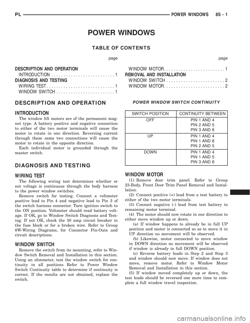
POWER WINDOWS
TABLE OF CONTENTS
page page
DESCRIPTION AND OPERATION
INTRODUCTION..........................1
DIAGNOSIS AND TESTING
WIRING TEST............................1
WINDOW SWITCH........................1WINDOW MOTOR.........................1
REMOVAL AND INSTALLATION
WINDOW SWITCH........................2
WINDOW MOTOR.........................2
DESCRIPTION AND OPERATION
INTRODUCTION
The window lift motors are of the permanent mag-
net type. A battery positive and negative connection
to either of the two motor terminals will cause the
motor to rotate in one direction. Reversing current
through these same two connections will cause the
motor to rotate in the opposite direction.
Each individual motor is grounded through the
master switch.
DIAGNOSIS AND TESTING
WIRING TEST
The following wiring test determines whether or
not voltage is continuous through the body harness
to the power window switches.
Remove switch for testing. Connect a voltmeter
positive lead to Pin 4 and negative lead to Pin 3 of
the switch harness connector. Turn ignition switch to
the ON position. Voltmeter should read battery volt-
age. If OK, go to Window Switch Diagnosis and Test-
ing. If not OK, check the 30 amp circuit breaker in
the fuse block or for a broken wire. Refer to Group
8W-Wiring Diagrams, for Connector Pin-Outs and
circuit descriptions.
WINDOW SWITCH
Remove the switch from its mounting, refer to Win-
dow Switch Removal and Installation in this section.
Using an ohmmeter, test the window switch for con-
tinuity in all positions Refer to Power Window
Switch Continuity table to determine if continuity is
correct. If the results are not obtained, replace the
switch.
WINDOW MOTOR
(1) Remove door trim panel. Refer to Group
23-Body, Front Door Trim Panel Removal and Instal-
lation.
(2) Connect positive (+) lead from a test battery to
either of the two motor terminals.
(3) Connect negative (-) lead from test battery to
remaining motor terminal.
(4) The motor should now rotate in one direction to
either move window up or down.
(a) If window happens to already be in full UP
position and motor is connected so as to move it in
UP direction no movement will be observed.
(b) Likewise, motor connected to move window
in DOWN direction no movement will be observed
if window is already in full DOWN position.
(c) Reverse battery leads in Step 2 and Step 3
and window should now move. If window does not
move, remove motor. Refer to Window Motor
Removal and Installation in this section.
(5) If window moved completely up or down, the
test leads should be reversed one more time to com-
plete a full window travel inspection.
POWER WINDOW SWITCH CONTINUITY
SWITCH POSITION CONTINUITY BETWEEN
OFF PIN 1 AND 4
PIN 2 AND 5
PIN 3 AND 8
UP PIN 1 AND 4
PIN 1 AND 8
PIN 2 AND 5
DOWN PIN 1 AND 4
PIN 1 AND 5
PIN 3 AND 8
PLPOWER WINDOWS 8S - 1
Page 382 of 1285
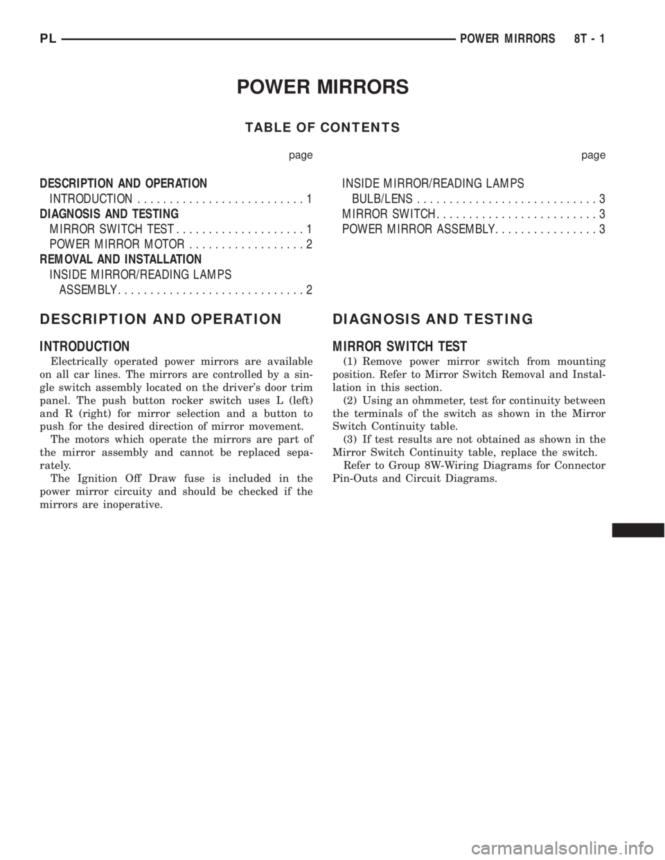
POWER MIRRORS
TABLE OF CONTENTS
page page
DESCRIPTION AND OPERATION
INTRODUCTION..........................1
DIAGNOSIS AND TESTING
MIRROR SWITCH TEST....................1
POWER MIRROR MOTOR..................2
REMOVAL AND INSTALLATION
INSIDE MIRROR/READING LAMPS
ASSEMBLY.............................2INSIDE MIRROR/READING LAMPS
BULB/LENS............................3
MIRROR SWITCH.........................3
POWER MIRROR ASSEMBLY................3
DESCRIPTION AND OPERATION
INTRODUCTION
Electrically operated power mirrors are available
on all car lines. The mirrors are controlled by a sin-
gle switch assembly located on the driver's door trim
panel. The push button rocker switch uses L (left)
and R (right) for mirror selection and a button to
push for the desired direction of mirror movement.
The motors which operate the mirrors are part of
the mirror assembly and cannot be replaced sepa-
rately.
The Ignition Off Draw fuse is included in the
power mirror circuity and should be checked if the
mirrors are inoperative.
DIAGNOSIS AND TESTING
MIRROR SWITCH TEST
(1) Remove power mirror switch from mounting
position. Refer to Mirror Switch Removal and Instal-
lation in this section.
(2) Using an ohmmeter, test for continuity between
the terminals of the switch as shown in the Mirror
Switch Continuity table.
(3) If test results are not obtained as shown in the
Mirror Switch Continuity table, replace the switch.
Refer to Group 8W-Wiring Diagrams for Connector
Pin-Outs and Circuit Diagrams.
PLPOWER MIRRORS 8T - 1
Page 383 of 1285
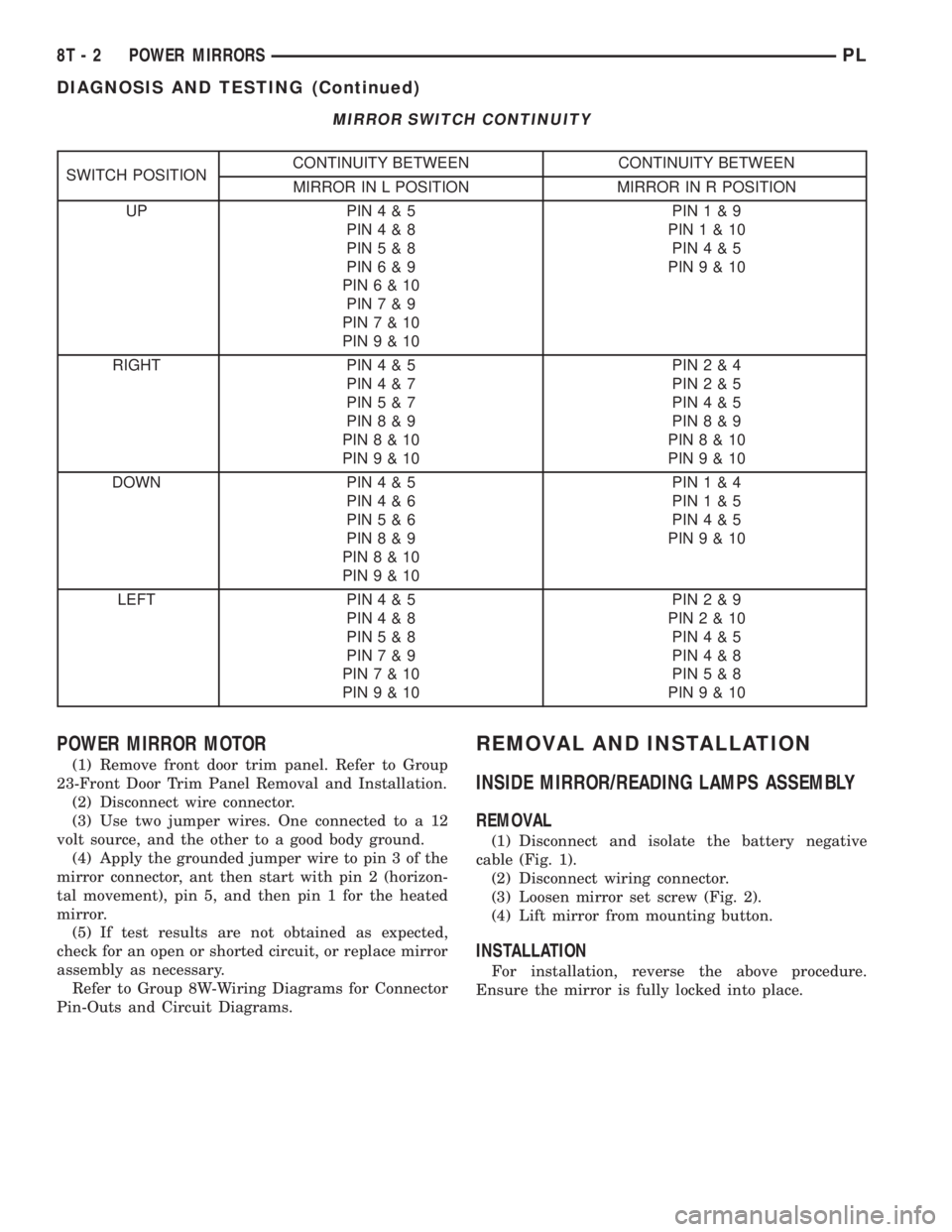
MIRROR SWITCH CONTINUITY
SWITCH POSITIONCONTINUITY BETWEEN CONTINUITY BETWEEN
MIRROR IN L POSITION MIRROR IN R POSITION
UP PIN4&5
PIN4&8
PIN5&8
PIN6&9
PIN6&10
PIN7&9
PIN7&10
PIN9&10PIN1&9
PIN1&10
PIN4&5
PIN9&10
RIGHT PIN4&5
PIN4&7
PIN5&7
PIN8&9
PIN8&10
PIN9&10PIN2&4
PIN2&5
PIN4&5
PIN8&9
PIN8&10
PIN9&10
DOWN PIN4&5
PIN4&6
PIN5&6
PIN8&9
PIN8&10
PIN9&10PIN1&4
PIN1&5
PIN4&5
PIN9&10
LEFT PIN4&5
PIN4&8
PIN5&8
PIN7&9
PIN7&10
PIN9&10PIN2&9
PIN2&10
PIN4&5
PIN4&8
PIN5&8
PIN9&10
POWER MIRROR MOTOR
(1) Remove front door trim panel. Refer to Group
23-Front Door Trim Panel Removal and Installation.
(2) Disconnect wire connector.
(3) Use two jumper wires. One connected to a 12
volt source, and the other to a good body ground.
(4) Apply the grounded jumper wire to pin 3 of the
mirror connector, ant then start with pin 2 (horizon-
tal movement), pin 5, and then pin 1 for the heated
mirror.
(5) If test results are not obtained as expected,
check for an open or shorted circuit, or replace mirror
assembly as necessary.
Refer to Group 8W-Wiring Diagrams for Connector
Pin-Outs and Circuit Diagrams.
REMOVAL AND INSTALLATION
INSIDE MIRROR/READING LAMPS ASSEMBLY
REMOVAL
(1) Disconnect and isolate the battery negative
cable (Fig. 1).
(2) Disconnect wiring connector.
(3) Loosen mirror set screw (Fig. 2).
(4) Lift mirror from mounting button.
INSTALLATION
For installation, reverse the above procedure.
Ensure the mirror is fully locked into place.
8T - 2 POWER MIRRORSPL
DIAGNOSIS AND TESTING (Continued)
Page 386 of 1285
POWER MIRRORS
TABLE OF CONTENTS
page page
GENERAL INFORMATION
INTRODUCTION..........................1
DIAGNOSIS AND TESTING
POWER FOLD AWAY MIRROR SWITCH TEST...1POWER FOLD AWAY MIRROR MOTOR........1
REMOVAL AND INSTALLATION
POWER FOLD-AWAY MIRROR SWITCH.......1
POWER FOLD-AWAY MIRROR...............2
GENERAL INFORMATION
INTRODUCTION
These vehicles may be equipped with Power Fold
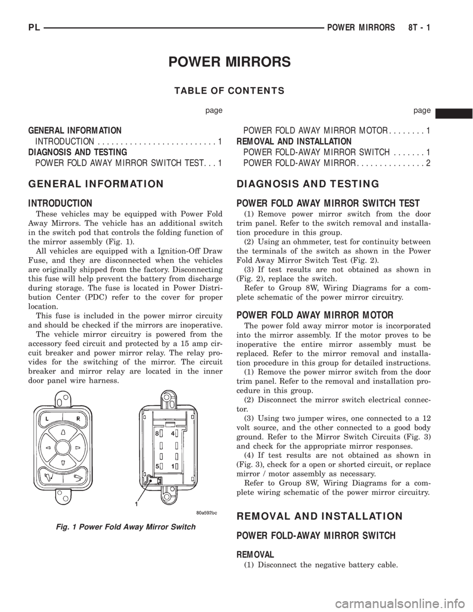
Away Mirrors. The vehicle has an additional switch
in the switch pod that controls the folding function of
the mirror assembly (Fig. 1).
All vehicles are equipped with a Ignition-Off Draw
Fuse, and they are disconnected when the vehicles
are originally shipped from the factory. Disconnecting
this fuse will help prevent the battery from discharge
during storage. The fuse is located in Power Distri-
bution Center (PDC) refer to the cover for proper
location.
This fuse is included in the power mirror circuity
and should be checked if the mirrors are inoperative.
The vehicle mirror circuitry is powered from the
accessory feed circuit and protected by a 15 amp cir-
cuit breaker and power mirror relay. The relay pro-
vides for the switching of the mirror. The circuit
breaker and mirror relay are located in the inner
door panel wire harness.
DIAGNOSIS AND TESTING
POWER FOLD AWAY MIRROR SWITCH TEST
(1) Remove power mirror switch from the door
trim panel. Refer to the switch removal and installa-
tion procedure in this group.
(2) Using an ohmmeter, test for continuity between
the terminals of the switch as shown in the Power
Fold Away Mirror Switch Test (Fig. 2).
(3) If test results are not obtained as shown in
(Fig. 2), replace the switch.
Refer to Group 8W, Wiring Diagrams for a com-
plete schematic of the power mirror circuitry.
POWER FOLD AWAY MIRROR MOTOR
The power fold away mirror motor is incorporated
into the mirror assembly. If the motor proves to be
inoperative the entire mirror assembly must be
replaced. Refer to the mirror removal and installa-
tion procedure in this group for detailed instructions.
(1) Remove the power mirror switch from the door
trim panel. Refer to the removal and installation pro-
cedure in this group.
(2) Disconnect the mirror switch electrical connec-
tor.
(3) Using two jumper wires, one connected to a 12
volt source, and the other connected to a good body
ground. Refer to the Mirror Switch Circuits (Fig. 3)
and check for the appropriate mirror responses.
(4) If test results are not obtained as shown in
(Fig. 3), check for a open or shorted circuit, or replace
mirror / motor assembly as necessary.
Refer to Group 8W, Wiring Diagrams for a com-
plete wiring schematic of the power mirror circuitry.
REMOVAL AND INSTALLATION
POWER FOLD-AWAY MIRROR SWITCH
REMOVAL
(1) Disconnect the negative battery cable.
Fig. 1 Power Fold Away Mirror Switch
PLPOWER MIRRORS 8T - 1