2000 DODGE NEON diagram
[x] Cancel search: diagramPage 183 of 1285
Radiator cooling fan control operation is accomplished
two ways. The fan always runs when the air condition-
ing compressor clutch is engaged. In addition to this
control, the fan is turned on by the temperature of the
coolant which is sensed by the coolant temperature sen-
sor which sends the message to the Powertrain Control
Module (PCM). The PCM turns on the fan through a
fan relay by grounding the relay's coil. The fan relay is
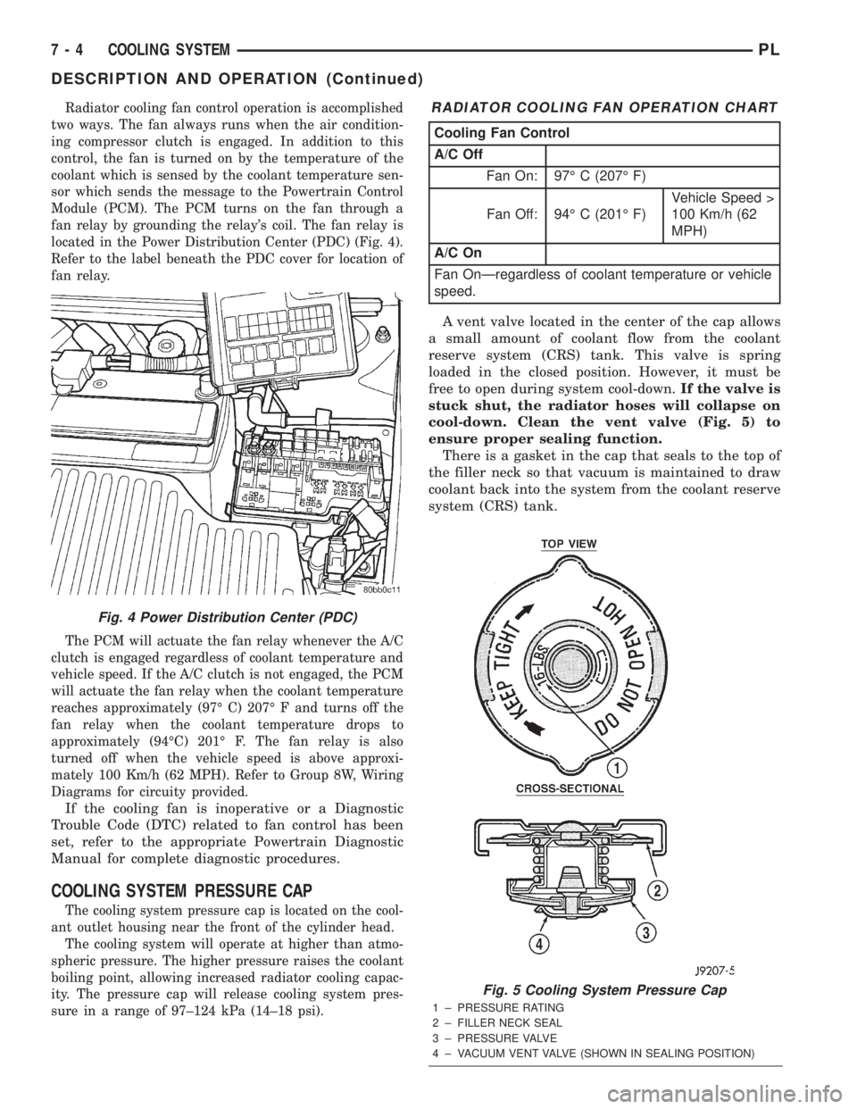
located in the Power Distribution Center (PDC) (Fig. 4).
Refer to the label beneath the PDC cover for location of
fan relay.
The PCM will actuate the fan relay whenever the A/C
clutch is engaged regardless of coolant temperature and
vehicle speed. If the A/C clutch is not engaged, the PCM
will actuate the fan relay when the coolant temperature
reaches approximately (97É C) 207É F and turns off the
fan relay when the coolant temperature drops to
approximately (94ÉC) 201É F. The fan relay is also
turned off when the vehicle speed is above approxi-
mately 100 Km/h (62 MPH). Refer to Group 8W, Wiring
Diagrams for circuity provided.
If the cooling fan is inoperative or a Diagnostic
Trouble Code (DTC) related to fan control has been
set, refer to the appropriate Powertrain Diagnostic
Manual for complete diagnostic procedures.
COOLING SYSTEM PRESSURE CAP
The cooling system pressure cap is located on the cool-
ant outlet housing near the front of the cylinder head.
The cooling system will operate at higher than atmo-
spheric pressure. The higher pressure raises the coolant
boiling point, allowing increased radiator cooling capac-
ity. The pressure cap will release cooling system pres-
sure in a range of 97±124 kPa (14±18 psi).
A vent valve located in the center of the cap allows
a small amount of coolant flow from the coolant
reserve system (CRS) tank. This valve is spring
loaded in the closed position. However, it must be
free to open during system cool-down.If the valve is
stuck shut, the radiator hoses will collapse on
cool-down. Clean the vent valve (Fig. 5) to
ensure proper sealing function.
There is a gasket in the cap that seals to the top of
the filler neck so that vacuum is maintained to draw
coolant back into the system from the coolant reserve
system (CRS) tank.
Fig. 4 Power Distribution Center (PDC)
RADIATOR COOLING FAN OPERATION CHART
Cooling Fan Control
A/C Off
Fan On: 97É C (207É F)
Fan Off: 94É C (201É F)Vehicle Speed >
100 Km/h (62
MPH)
A/C On
Fan OnÐregardless of coolant temperature or vehicle
speed.
Fig. 5 Cooling System Pressure Cap
1 ± PRESSURE RATING
2 ± FILLER NECK SEAL
3 ± PRESSURE VALVE
4 ± VACUUM VENT VALVE (SHOWN IN SEALING POSITION)
7 - 4 COOLING SYSTEMPL
DESCRIPTION AND OPERATION (Continued)
Page 202 of 1285
INSTALLATION
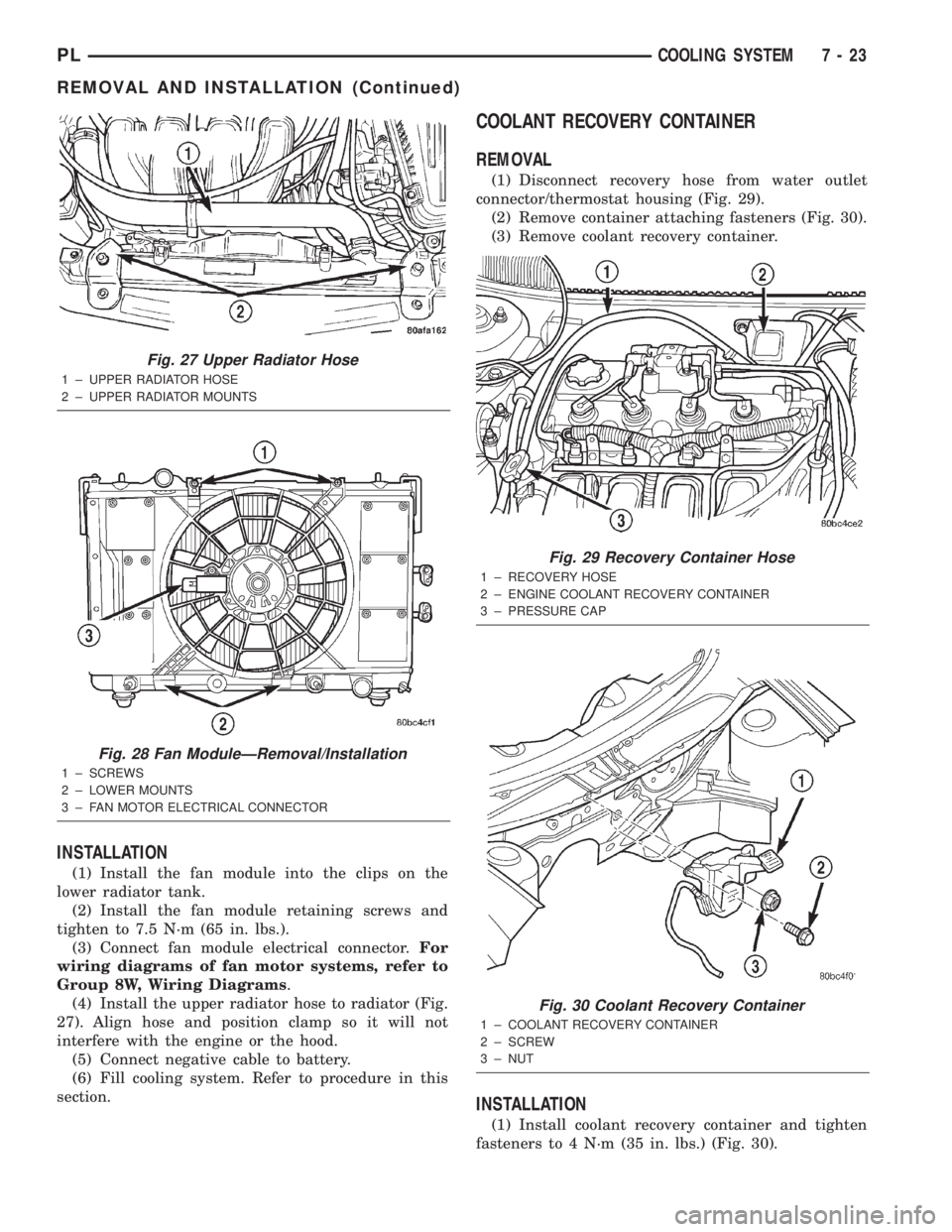
(1) Install the fan module into the clips on the
lower radiator tank.
(2) Install the fan module retaining screws and
tighten to 7.5 N´m (65 in. lbs.).
(3) Connect fan module electrical connector.For
wiring diagrams of fan motor systems, refer to
Group 8W, Wiring Diagrams.
(4) Install the upper radiator hose to radiator (Fig.
27). Align hose and position clamp so it will not
interfere with the engine or the hood.
(5) Connect negative cable to battery.
(6) Fill cooling system. Refer to procedure in this
section.
COOLANT RECOVERY CONTAINER
REMOVAL
(1) Disconnect recovery hose from water outlet
connector/thermostat housing (Fig. 29).
(2) Remove container attaching fasteners (Fig. 30).
(3) Remove coolant recovery container.
INSTALLATION
(1) Install coolant recovery container and tighten
fasteners to 4 N´m (35 in. lbs.) (Fig. 30).
Fig. 27 Upper Radiator Hose
1 ± UPPER RADIATOR HOSE
2 ± UPPER RADIATOR MOUNTS
Fig. 28 Fan ModuleÐRemoval/Installation
1 ± SCREWS
2 ± LOWER MOUNTS
3 ± FAN MOTOR ELECTRICAL CONNECTOR
Fig. 29 Recovery Container Hose
1 ± RECOVERY HOSE
2 ± ENGINE COOLANT RECOVERY CONTAINER
3 ± PRESSURE CAP
Fig. 30 Coolant Recovery Container
1 ± COOLANT RECOVERY CONTAINER
2 ± SCREW
3 ± NUT
PLCOOLING SYSTEM 7 - 23
REMOVAL AND INSTALLATION (Continued)
Page 214 of 1285
be checked. To determine if a high current draw con-
dition exists first check the vehicle with a test lamp.
(1) Verify that all electrical accessories are OFF.
²Remove key from ignition switch
²Turn off all lights
²Trunk lid is closed
²Engine compartment hood lamp is disconnected
or lamp removed
²Map lamp on rear view mirror
²Glove box door is closed
²Sun visor vanity lights are OFF
²All doors are closed
²Allow the ignition key lamp system to time out
in approximately 30 seconds, if equipped.
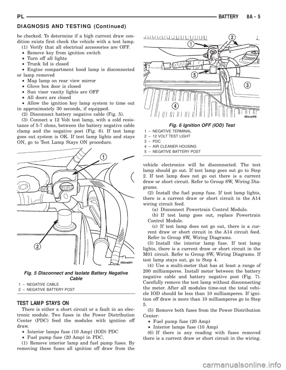
(2) Disconnect battery negative cable (Fig. 5).
(3) Connect a 12 Volt test lamp, with a cold resis-
tance of 5-7 ohms, between the battery negative cable
clamp and the negative post (Fig. 6). If test lamp
goes out system is OK. If test lamp lights and stays
ON, go to Test Lamp Stays ON procedure.
TEST LAMP STAYS ON
There is either a short circuit or a fault in an elec-
tronic module. Two fuses in the Power Distribution
Center (PDC) feed the modules with ignition off
draw.
²Interior lamps fuse (10 Amp) (IOD) PDC
²Fuel pump fuse (20 Amp) in PDC.
(1) Remove interior lamp and fuel pump fuses. By
removing these fuses all ignition off draw from thevehicle electronics will be disconnected. The test
lamp should go out. If test lamp goes out go to Step
2. If test lamp does not go out there is a current
draw or short circuit. Refer to Group 8W, Wiring Dia-
grams.
(2) Install the fuel pump fuse. If test lamp lights,
there is a current draw or short circuit in the A14
wiring circuit feed.
(a) Disconnect Powertrain Control Module.
(b) If test lamp goes out, replace Powertrain
Control Module.
(c) If test lamp does not go out, there is a cur-
rent draw or short circuit in the A14 circuit feed.
Refer to Group 8W, Wiring Diagrams.
(3) Install the interior lamp fuse. If test lamp
lights, there is a current draw or short circuit in the
M01 circuit. Refer to Group 8W, Wiring Diagrams. If
test lamp stays out, go to Step 4.
(4) Use a multi-meter that has at least a range of
200 milliamperes. Install meter between the battery
negative cable and battery negative post (Fig. 7).
Carefully remove the test lamp without disconnecting
the meter. After all modules time-out the total vehi-
cle IOD should be less than 10 milliamperes. If igni-
tion off draw is more than 10 milliamperes go to Step
5.
(5) Remove both fuses from the Power Distribution
Center:
²Fuel pump fuse (20 Amp)
²Interior lamps fuse (10 Amp)
(6) If there is any reading with fuses removed
there is a current draw or short circuit in the wiring.
Fig. 5 Disconnect and Isolate Battery Negative
Cable
1 ± NEGATIVE CABLE
2 ± NEGATIVE BATTERY POST
Fig. 6 Ignition OFF (IOD) Test
1 ± NEGATIVE TERMINAL
2 ± 12 VOLT TEST LIGHT
3 ± PDC
4 ± AIR CLEANER HOUSING
5 ± NEGATIVE BATTERY POST
PLBATTERY 8A - 5
DIAGNOSIS AND TESTING (Continued)
Page 215 of 1285
Refer to Group 8W, Wiring Diagrams. If OK go to
Step 7.
(7) Install interior lamp fuse. After installing fuse,
the current can reach 250 milliamperes. After time-
out the reading should not exceed 8 milliamperes. If
NOT OK go to Step 8. If OK go to Step 9.
²Ignition key lamp system
²Radio
²Remote keyless entry module, if equipped
(8) Disconnect radio and ignition switch key lamp
one component at time, to see if any component is at
fault. If the high reading is not eliminated there is a
short circuit in the wiring. Refer to Group 8W, Wir-
ing Diagrams.
CAUTION: Always disconnect the meter before
opening a door.
(9) Remove interior lamps fuse and install the fuel
pump fuse. The reading should be between 1-3 milli-
amperes. If reading is higher than 3 milliamperes:
(a) Disconnect Powertrain Control Module.
(b) If reading drops to zero, replace Powertrain
Control Module.
(c) If reading remains the same there is a cur-
rent draw or short circuit in the A14 circuit. Refer
to Group 8W, Wiring Diagrams.
BATTERY LOAD TEST
A fully charged battery must have cranking capac-
ity, to provide the starter motor and ignition system
enough power to start the engine over a broad range
of ambient temperatures. A battery load test will ver-
ify the actual cranking capability of the battery.WARNING: IF BATTERY SHOWS SIGNS OF FREEZ-
ING, LEAKING, LOOSE POSTS, OR EXCESSIVELY
LOW ELECTROLYTE LEVEL, DO NOT TEST. ACID
BURNS OR AN EXPLOSIVE CONDITION MAY
RESULT.
(1) Remove both battery cables, negative cable
first. The battery top, cables and posts should be
clean. If green dot is not visible in indicator, charge
the battery. Refer to Battery Charging Procedures in
this group.
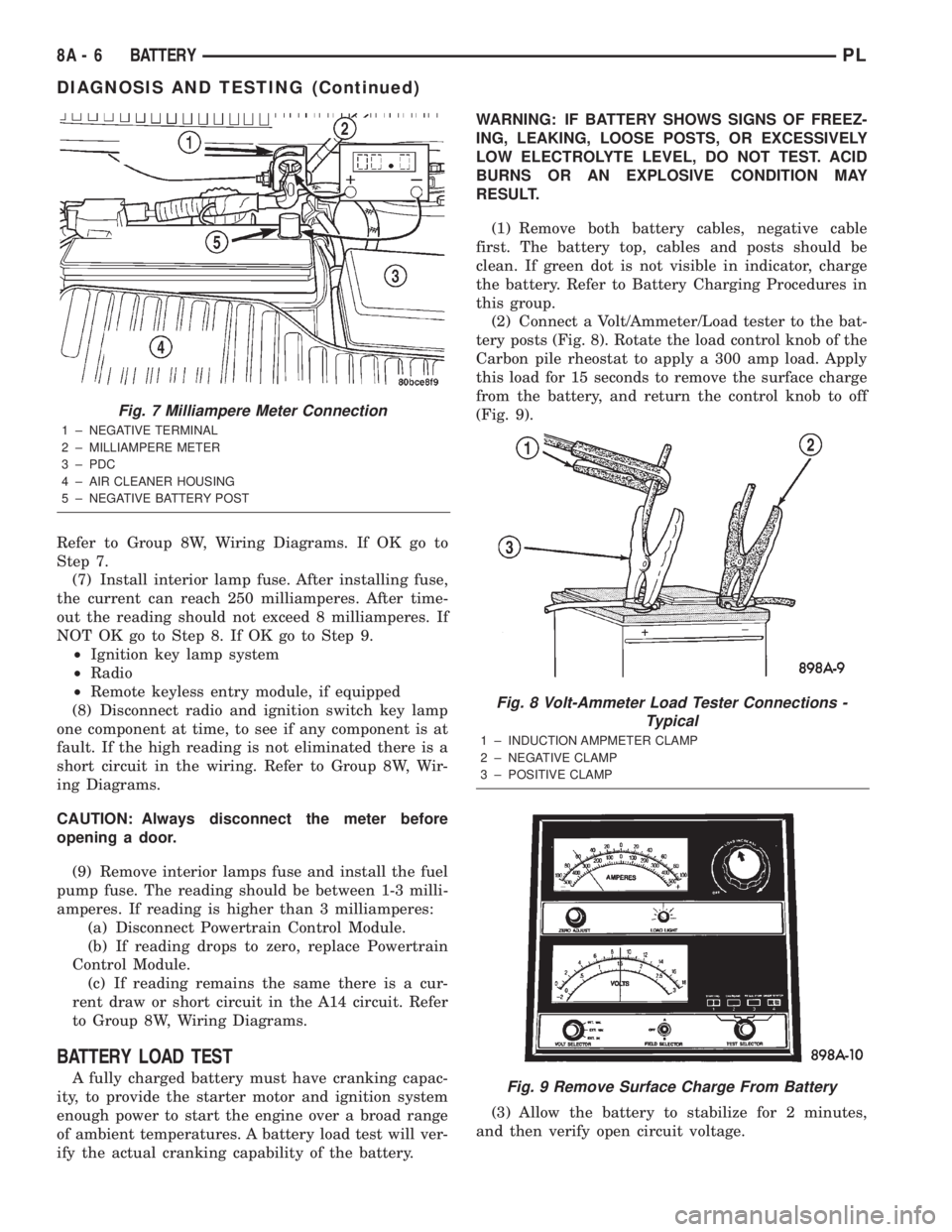
(2) Connect a Volt/Ammeter/Load tester to the bat-
tery posts (Fig. 8). Rotate the load control knob of the
Carbon pile rheostat to apply a 300 amp load. Apply
this load for 15 seconds to remove the surface charge
from the battery, and return the control knob to off
(Fig. 9).
(3) Allow the battery to stabilize for 2 minutes,
and then verify open circuit voltage.
Fig. 7 Milliampere Meter Connection
1 ± NEGATIVE TERMINAL
2 ± MILLIAMPERE METER
3 ± PDC
4 ± AIR CLEANER HOUSING
5 ± NEGATIVE BATTERY POST
Fig. 8 Volt-Ammeter Load Tester Connections -
Typical
1 ± INDUCTION AMPMETER CLAMP
2 ± NEGATIVE CLAMP
3 ± POSITIVE CLAMP
Fig. 9 Remove Surface Charge From Battery
8A - 6 BATTERYPL
DIAGNOSIS AND TESTING (Continued)
Page 224 of 1285
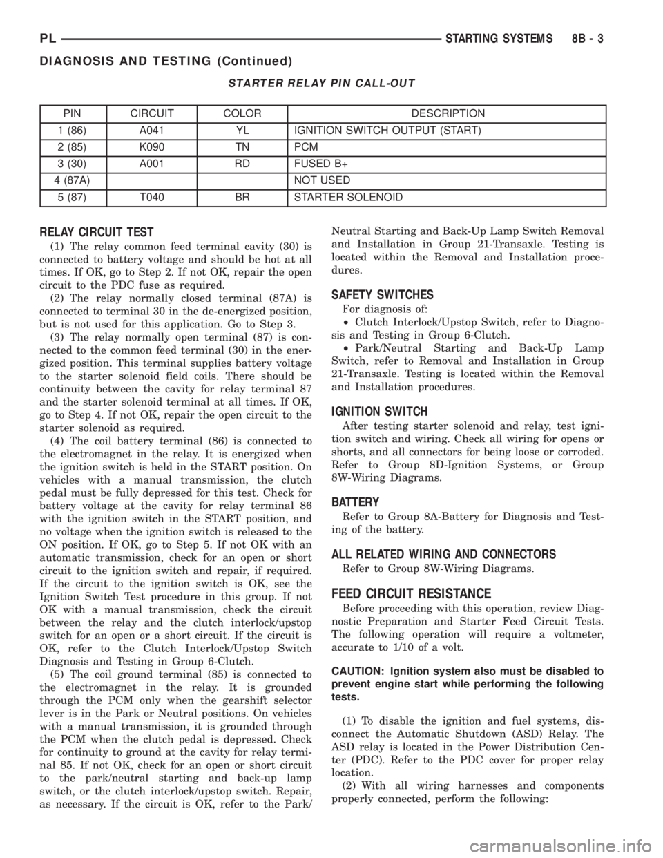
STARTER RELAY PIN CALL-OUT
PIN CIRCUIT COLOR DESCRIPTION
1 (86) A041 YL IGNITION SWITCH OUTPUT (START)
2 (85) K090 TN PCM
3 (30) A001 RD FUSED B+
4 (87A) NOT USED
5 (87) T040 BR STARTER SOLENOID
RELAY CIRCUIT TEST
(1) The relay common feed terminal cavity (30) is
connected to battery voltage and should be hot at all
times. If OK, go to Step 2. If not OK, repair the open
circuit to the PDC fuse as required.
(2) The relay normally closed terminal (87A) is
connected to terminal 30 in the de-energized position,
but is not used for this application. Go to Step 3.
(3) The relay normally open terminal (87) is con-
nected to the common feed terminal (30) in the ener-
gized position. This terminal supplies battery voltage
to the starter solenoid field coils. There should be
continuity between the cavity for relay terminal 87
and the starter solenoid terminal at all times. If OK,
go to Step 4. If not OK, repair the open circuit to the
starter solenoid as required.
(4) The coil battery terminal (86) is connected to
the electromagnet in the relay. It is energized when
the ignition switch is held in the START position. On
vehicles with a manual transmission, the clutch
pedal must be fully depressed for this test. Check for
battery voltage at the cavity for relay terminal 86
with the ignition switch in the START position, and
no voltage when the ignition switch is released to the
ON position. If OK, go to Step 5. If not OK with an
automatic transmission, check for an open or short
circuit to the ignition switch and repair, if required.
If the circuit to the ignition switch is OK, see the
Ignition Switch Test procedure in this group. If not
OK with a manual transmission, check the circuit
between the relay and the clutch interlock/upstop
switch for an open or a short circuit. If the circuit is
OK, refer to the Clutch Interlock/Upstop Switch
Diagnosis and Testing in Group 6-Clutch.
(5) The coil ground terminal (85) is connected to
the electromagnet in the relay. It is grounded
through the PCM only when the gearshift selector
lever is in the Park or Neutral positions. On vehicles
with a manual transmission, it is grounded through
the PCM when the clutch pedal is depressed. Check
for continuity to ground at the cavity for relay termi-
nal 85. If not OK, check for an open or short circuit
to the park/neutral starting and back-up lamp
switch, or the clutch interlock/upstop switch. Repair,
as necessary. If the circuit is OK, refer to the Park/Neutral Starting and Back-Up Lamp Switch Removal
and Installation in Group 21-Transaxle. Testing is
located within the Removal and Installation proce-
dures.
SAFETY SWITCHES
For diagnosis of:
²Clutch Interlock/Upstop Switch, refer to Diagno-
sis and Testing in Group 6-Clutch.
²Park/Neutral Starting and Back-Up Lamp
Switch, refer to Removal and Installation in Group
21-Transaxle. Testing is located within the Removal
and Installation procedures.
IGNITION SWITCH
After testing starter solenoid and relay, test igni-
tion switch and wiring. Check all wiring for opens or
shorts, and all connectors for being loose or corroded.
Refer to Group 8D-Ignition Systems, or Group
8W-Wiring Diagrams.
BATTERY
Refer to Group 8A-Battery for Diagnosis and Test-
ing of the battery.
ALL RELATED WIRING AND CONNECTORS
Refer to Group 8W-Wiring Diagrams.
FEED CIRCUIT RESISTANCE
Before proceeding with this operation, review Diag-
nostic Preparation and Starter Feed Circuit Tests.
The following operation will require a voltmeter,
accurate to 1/10 of a volt.
CAUTION: Ignition system also must be disabled to
prevent engine start while performing the following
tests.
(1) To disable the ignition and fuel systems, dis-
connect the Automatic Shutdown (ASD) Relay. The
ASD relay is located in the Power Distribution Cen-
ter (PDC). Refer to the PDC cover for proper relay
location.
(2) With all wiring harnesses and components
properly connected, perform the following:
PLSTARTING SYSTEMS 8B - 3
DIAGNOSIS AND TESTING (Continued)
Page 227 of 1285
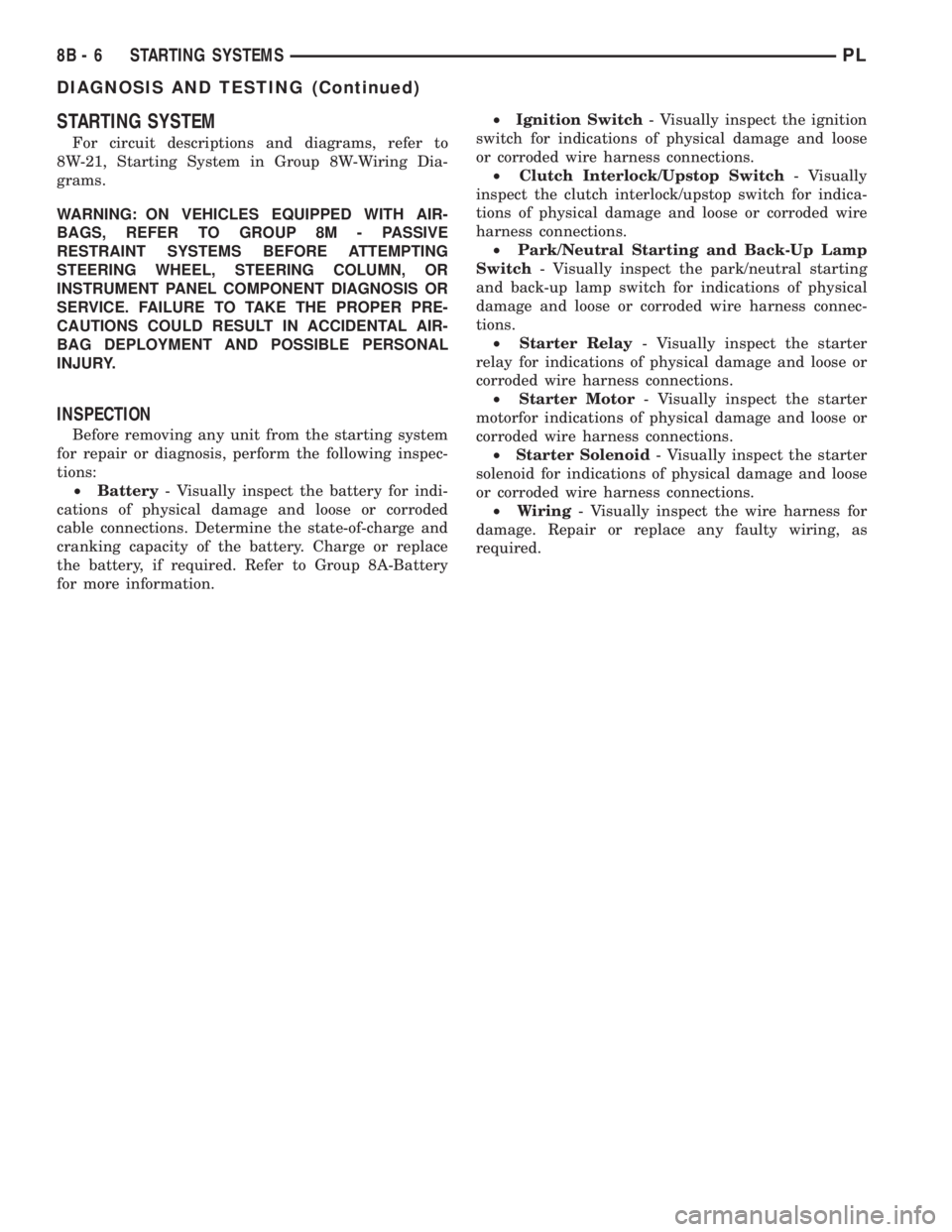
STARTING SYSTEM
For circuit descriptions and diagrams, refer to
8W-21, Starting System in Group 8W-Wiring Dia-
grams.
WARNING: ON VEHICLES EQUIPPED WITH AIR-
BAGS, REFER TO GROUP 8M - PASSIVE
RESTRAINT SYSTEMS BEFORE ATTEMPTING
STEERING WHEEL, STEERING COLUMN, OR
INSTRUMENT PANEL COMPONENT DIAGNOSIS OR
SERVICE. FAILURE TO TAKE THE PROPER PRE-
CAUTIONS COULD RESULT IN ACCIDENTAL AIR-
BAG DEPLOYMENT AND POSSIBLE PERSONAL
INJURY.
INSPECTION
Before removing any unit from the starting system
for repair or diagnosis, perform the following inspec-
tions:
²Battery- Visually inspect the battery for indi-
cations of physical damage and loose or corroded
cable connections. Determine the state-of-charge and
cranking capacity of the battery. Charge or replace
the battery, if required. Refer to Group 8A-Battery
for more information.²Ignition Switch- Visually inspect the ignition
switch for indications of physical damage and loose
or corroded wire harness connections.
²Clutch Interlock/Upstop Switch- Visually
inspect the clutch interlock/upstop switch for indica-
tions of physical damage and loose or corroded wire
harness connections.
²Park/Neutral Starting and Back-Up Lamp
Switch- Visually inspect the park/neutral starting
and back-up lamp switch for indications of physical
damage and loose or corroded wire harness connec-
tions.
²Starter Relay- Visually inspect the starter
relay for indications of physical damage and loose or
corroded wire harness connections.
²Starter Motor- Visually inspect the starter
motorfor indications of physical damage and loose or
corroded wire harness connections.
²Starter Solenoid- Visually inspect the starter
solenoid for indications of physical damage and loose
or corroded wire harness connections.
²Wiring- Visually inspect the wire harness for
damage. Repair or replace any faulty wiring, as
required.
8B - 6 STARTING SYSTEMSPL
DIAGNOSIS AND TESTING (Continued)
Page 228 of 1285
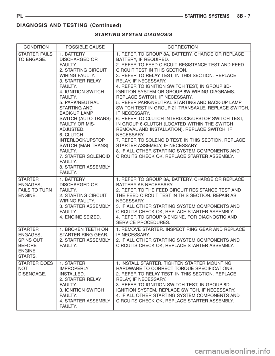
STARTING SYSTEM DIAGNOSIS
CONDITION POSSIBLE CAUSE CORRECTION
STARTER FAILS
TO ENGAGE.1. BATTERY
DISCHARGED OR
FAULTY.
2. STARTING CIRCUIT
WIRING FAULTY.
3. STARTER RELAY
FAULTY.
4. IGNITION SWITCH
FAULTY.
5. PARK/NEUTRAL
STARTING AND
BACK-UP LAMP
SWITCH (AUTO TRANS)
FAULTY OR MIS-
ADJUSTED.
6. CLUTCH
INTERLOCK/UPSTOP
SWITCH (MAN TRANS)
FAULTY.
7. STARTER SOLENOID
FAULTY.
8. STARTER ASSEMBLY
FAULTY.1. REFER TO GROUP 8A, BATTERY. CHARGE OR REPLACE
BATTERY, IF REQUIRED.
2. REFER TO FEED CIRCUIT RESISTANCE TEST AND FEED
CIRCUIT TEST IN THIS SECTION.
3. REFER TO RELAY TEST, IN THIS SECTION. REPLACE
RELAY, IF NECESSARY.
4. REFER TO IGNITION SWITCH TEST, IN GROUP 8D-
IGNITION SYSTEM OR GROUP 8W-WIRING DIAGRAMS.
REPLACE SWITCH, IF NECESSARY.
5. REFER PARK/NEUTRAL STARTING AND BACK-UP LAMP
SWITCH TEST IN GROUP 21-TRANSAXLE. REPLACE SWITCH,
IF NECESSARY.
6. REFER TO CLUTCH INTERLOCK/UPSTOP SWITCH TEST,
IN GROUP 6-CLUTCH (LOCATED WITHIN THE SWITCH
REMOVAL AND INSTALLATION). REPLACE SWITCH, IF
NECESSARY.
7. REFER TO SOLENOID TEST, IN THIS SECTION. REPLACE
STARTER ASSEMBLY, IF NECESSARY.
8. IF ALL OTHER STARTING SYSTEM COMPONENTS AND
CIRCUITS CHECK OK, REPLACE STARTER ASSEMBLY.
STARTER
ENGAGES,
FAILS TO TURN
ENGINE.1. BATTERY
DISCHARGED OR
FAULTY.
2. STARTING CIRCUIT
WIRING FAULTY.
3. STARTER ASSEMBLY
FAULTY.
4. ENGINE SEIZED.1. REFER TO GROUP 8A, BATTERY. CHARGE OR REPLACE
BATTERY AS NECESSARY.
2. REFER TO THE FEED CIRCUIT RESISTANCE TEST AND
THE FEED CIRCUIT TEST IN THIS SECTION. REPAIR AS
NECESSARY.
3. IF ALL OTHER STARTING SYSTEM COMPONENTS AND
CIRCUITS CHECK OK, REPLACE STARTER ASSEMBLY.
4. REFER TO GROUP 9-ENGINE, FOR DIAGNOSTIC AND
SERVICE PROCEDURES.
STARTER
ENGAGES,
SPINS OUT
BEFORE
ENGINE
STARTS.1. BROKEN TEETH ON
STARTER RING GEAR.
2. STARTER ASSEMBLY
FAULTY.1. REMOVE STARTER. INSPECT RING GEAR AND REPLACE
IF NECESSARY.
2. IF ALL OTHER STARTING SYSTEM COMPONENTS AND
CIRCUITS CHECK OK, REPLACE STARTER ASSEMBLY.
STARTER DOES
NOT
DISENGAGE.1. STARTER
IMPROPERLY
INSTALLED.
2. STARTER RELAY
FAULTY.
3. IGNITION SWITCH
FAULTY.
4. STARTER ASSEMBLY
FAULTY.1. INSTALL STARTER. TIGHTEN STARTER MOUNTING
HARDWARE TO CORRECT TORQUE SPECIFICATIONS.
2. REFER TO RELAY TEST, IN THIS SECTION. REPLACE
RELAY, IF NECESSARY.
3. REFER TO IGNITION SWITCH TEST, IN GROUP 8D-
IGNITION SYSTEM. REPLACE SWITCH, IF NECESSARY.
4. IF ALL OTHER STARTING SYSTEM COMPONENTS AND
CIRCUITS CHECK OK, REPLACE STARTER ASSEMBLY.
PLSTARTING SYSTEMS 8B - 7
DIAGNOSIS AND TESTING (Continued)
Page 238 of 1285
OPERATION
The Automatic Shutdown (ASD) relay supplies bat-
tery voltage to the fuel injectors, electronic ignition
coil and the heating elements in the oxygen sensors.
A buss bar in the Power Distribution Center (PDC)
supplies voltage to the solenoid side and contact side
of the relay. The fuse also protects the power circuit
for the fuel pump relay and pump. The fuse is
located in the PDC. Refer to the Wiring Diagrams for
circuit information.
The PCM controls the ASD relay by switching the
ground path for the solenoid side of the relay on and
off. The PCM turns the ground path off when the
ignition switch is in the Off position. When the igni-
tion switch is in On or Start, the PCM monitors the
crankshaft and camshaft position sensor signals to
determine engine speed and ignition timing (coil
dwell). If the PCM does not receive crankshaft and
camshaft position sensor signals when the ignition
switch is in the Run position, it will de-energize the
ASD relay.
CRANKSHAFT POSITION SENSORÐPCM
INPUT
DESCRIPTION
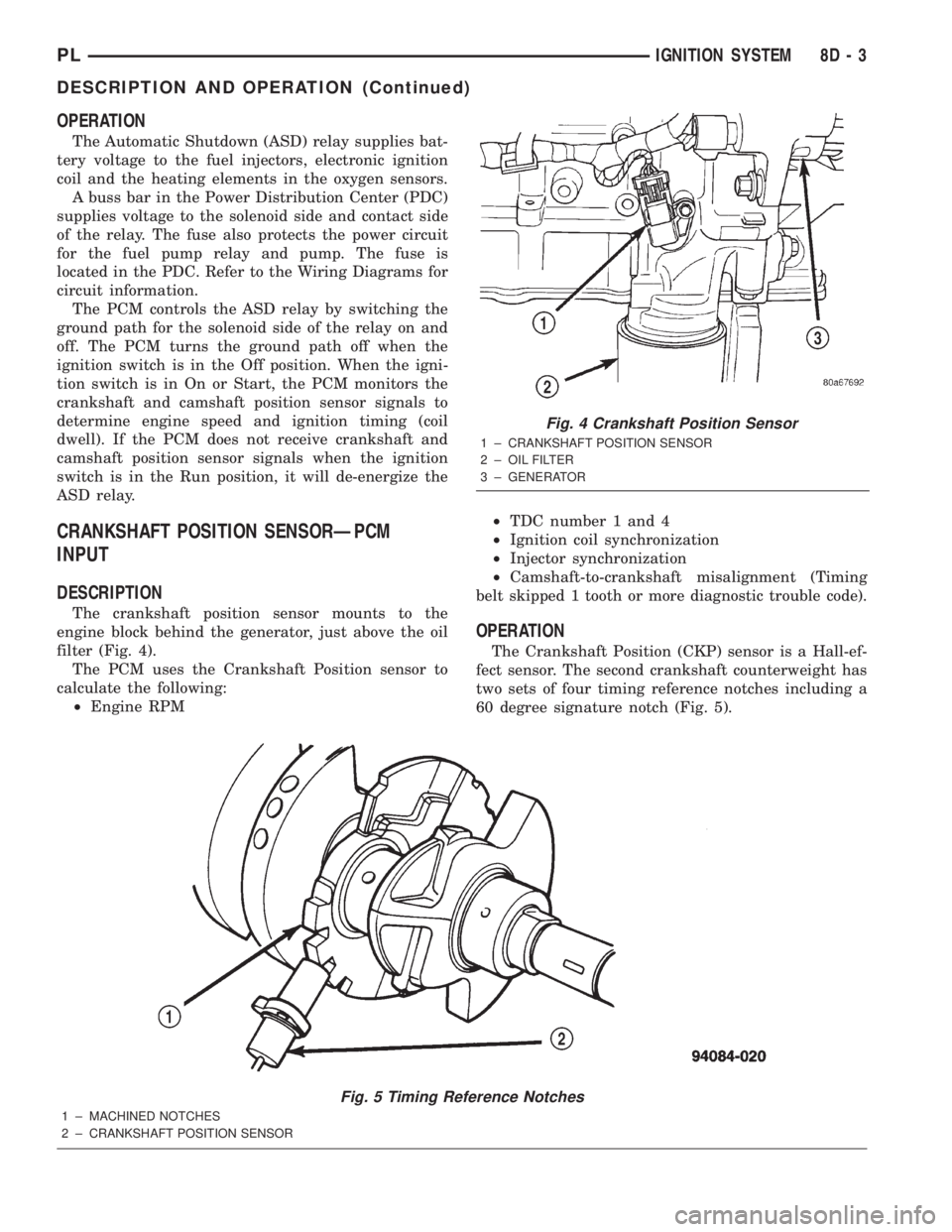
The crankshaft position sensor mounts to the
engine block behind the generator, just above the oil
filter (Fig. 4).
The PCM uses the Crankshaft Position sensor to
calculate the following:
²Engine RPM²TDC number 1 and 4
²Ignition coil synchronization
²Injector synchronization
²Camshaft-to-crankshaft misalignment (Timing
belt skipped 1 tooth or more diagnostic trouble code).
OPERATION
The Crankshaft Position (CKP) sensor is a Hall-ef-
fect sensor. The second crankshaft counterweight has
two sets of four timing reference notches including a
60 degree signature notch (Fig. 5).
Fig. 5 Timing Reference Notches
1 ± MACHINED NOTCHES
2 ± CRANKSHAFT POSITION SENSOR
Fig. 4 Crankshaft Position Sensor
1 ± CRANKSHAFT POSITION SENSOR
2 ± OIL FILTER
3 ± GENERATOR
PLIGNITION SYSTEM 8D - 3
DESCRIPTION AND OPERATION (Continued)