2000 DODGE NEON diagram
[x] Cancel search: diagramPage 1 of 1285

GROUP TAB LOCATORINIntroductionINaIntroduction0Lubrication and Maintenance2Suspension3Differential and Driveline5Brakes6Clutch7Cooling8ABattery8BStarting8CCharging System8DIgnition System8EInstrument Panel and Systems8EaInstrument Panel and Systems8FAudio System8GHorns8HVehicle Speed Control System8JTurn Signal and Flashers8KWindshield Wipers and Washers8LLamps8LaLamps8MRestraint System8NElectrically Heated Systems8OPower Distribution Systems8PPower Door Locks8QImmobilizer System8SPower Windows8TPower Mirrors8TaPower Mirrors8UChime Warning/Reminder System8WWiring Diagrams - LHD and RHD9Engine11Exhaust System13Frame and Bumpers14Fuel System19Steering21Transaxle22Tires and Wheels23Body24Heating and Air Conditioning24aHeating and Air Conditioning25Emission Control Systems
Page 144 of 1285
ANTILOCK BRAKE SYSTEM
TABLE OF CONTENTS
page page
DESCRIPTION AND OPERATION
ANTILOCK BRAKE SYSTEM OPERATION......65
ANTILOCK BRAKE SYSTEM COMPONENTS....66
ELECTRONIC BRAKE DISTRIBUTION.........69
TRACTION CONTROL SYSTEM..............70
HYDRAULIC CIRCUITS AND VALVE
OPERATION...........................71
DIAGNOSIS AND TESTING
SERVICE WARNINGS AND CAUTIONS........74
ABS GENERAL DIAGNOSTICS INFORMATION . . 74
ABS WIRING DIAGRAM INFORMATION........74
ABS VEHICLE TEST DRIVE.................74
ABS ELECTRONIC DIAGNOSIS..............75
TONE WHEEL...........................76
BRAKE FLUID CONTAMINATION.............76
SERVICE PROCEDURES
BRAKE FLUID LEVEL CHECKING............77ANTILOCK BRAKE SYSTEM BLEEDING.......77
MASTER CYLINDER BLEEDING.............77
REMOVAL AND INSTALLATION
SERVICE WARNINGS AND CAUTIONS........78
MASTER CYLINDER......................78
INTEGRATED CONTROL UNIT...............79
WHEEL SPEED SENSOR (FRONT)...........81
WHEEL SPEED SENSOR (REAR)............83
DISASSEMBLY AND ASSEMBLY
INTEGRATED CONTROL UNIT...............84
SPECIFICATIONS
TONE WHEEL RUNOUT....................85
WHEEL SPEED SENSOR-TO-TONE WHEEL
CLEARANCE...........................85
BRAKE FASTENER TORQUE
SPECIFICATIONS.......................85
DESCRIPTION AND OPERATION
ANTILOCK BRAKE SYSTEM OPERATION
This section covers the physical and operational
descriptions, and the on-car service procedures for
the Mark 20e Antilock Brake System (ABS) with
traction control. It is the only antilock brake system
available on this vehicle.
The purpose of the antilock brake system is to pre-
vent wheel lockup under braking conditions on virtu-
ally any type of road surface. Antilock braking is
desirable because a vehicle that is stopped without
locking the wheels retains directional stability and
some steering capability. This allows the driver to
retain greater control of the vehicle during braking.
The traction control system reduces wheel slip and
maintains traction at the driving speeds below 56
kph (35 mph) when road conditions call for traction
assistance. Refer to TRACTION CONTROL SYSTEM
in this section for more information.
Vehicles equipped with ABS use electronic brake
distribution (EBD) to balance front-to-rear braking
when the brakes are applied in the partial braking
range. Refer to ELECTRONIC BRAKE DISTRIBU-
TION in this section for more information.
There are a few performance characteristics of the
Mark 20e Antilock Brake System that may at first
seem abnormal, but in fact are normal. These char-
acteristics are described below.
NORMAL BRAKING
Under normal braking conditions, the ABS func-
tions the same as a standard base brake system with
a diagonally split master cylinder and conventional
vacuum assist.
ABS BRAKING
ABS operation is available at all vehicle speeds
above 3±5 mph. If a wheel locking tendency is
detected during a brake application, the brake sys-
tem enters the ABS mode. During ABS braking,
hydraulic pressure in the four wheel circuits is mod-
ulated to prevent any wheel from locking. Each
wheel circuit is designed with a set of electric sole-
noids to allow modulation, although for vehicle sta-
bility, both rear wheel solenoids receive the same
electrical signal. Wheel lockup may be perceived at
the very end of an ABS stop and is considered nor-
mal.
During an ABS stop, the brakes hydraulic system
is still diagonally split. However, the brake system
pressure is further split into four control channels.
During antilock operation of the vehicle's brake sys-
tem, the wheels are controlled independently and are
on separate control channels.
The system can build, hold and release pressure at
each wheel, depending on signals generated by the
wheel speed sensors (WSS) at each wheel and
received at the controller antilock brake (CAB).
PLBRAKES 5 - 65
Page 150 of 1285
If the CAB calculates that the brake temperatures
are high, the traction control system becomes inoper-
ative until a time-out period has elapsed. During this
ªthermo-protection mode,º the traction control func-
tion lamp illuminates TRAC OFF; note that no trou-
ble code is registered.
HYDRAULIC CIRCUITS AND VALVE OPERATION
The hydraulic shuttle valves control the flow of
pressurized brake fluid to the wheel brakes during
the different modes of ABS braking. The following
paragraphs explain how this works. For purposes of
explanation only, it is assumed that only the right
front wheel is experiencing antilock braking; the fol-
lowing diagrams show only the right front wheel in
an antilock braking operation.
NORMAL BRAKING HYDRAULIC CIRCUIT,
SOLENOID VALVE, AND SHUTTLE VALVE
FUNCTION (ABS WITH TRACTION CONTROL)
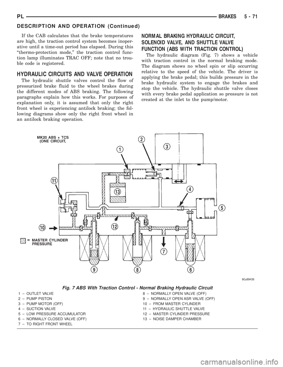
The hydraulic diagram (Fig. 7) shows a vehicle
with traction control in the normal braking mode.
The diagram shows no wheel spin or slip occurring
relative to the speed of the vehicle. The driver is
applying the brake pedal; this builds pressure in the
brake hydraulic system to engage the brakes and
stop the vehicle. The hydraulic shuttle valve closes
with every brake pedal application so pressure is not
created at the inlet to the pump/motor.
Fig. 7 ABS With Traction Control - Normal Braking Hydraulic Circuit
1 ± OUTLET VALVE
2 ± PUMP PISTON
3 ± PUMP MOTOR (OFF)
4 ± SUCTION VALVE
5 ± LOW PRESSURE ACCUMULATOR
6 ± NORMALLY CLOSED VALVE (OFF)
7 ± TO RIGHT FRONT WHEEL8 ± NORMALLY OPEN VALVE (OFF)
9 ± NORMALLY OPEN ASR VALVE (OFF)
10 ± FROM MASTER CYLINDER
11 ± HYDRAULIC SHUTTLE VALVE
12 ± MASTER CYLINDER PRESSURE
13 ± NOISE DAMPER CHAMBER
PLBRAKES 5 - 71
DESCRIPTION AND OPERATION (Continued)
Page 151 of 1285
ABS BRAKING HYDRAULIC CIRCUIT, SOLENOID
VALVE, AND SHUTTLE VALVE FUNCTION (ABS
WITH TRACTION CONTROL)
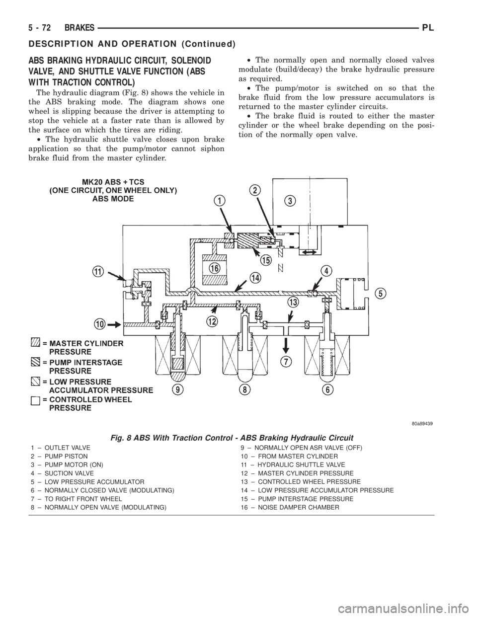
The hydraulic diagram (Fig. 8) shows the vehicle in
the ABS braking mode. The diagram shows one
wheel is slipping because the driver is attempting to
stop the vehicle at a faster rate than is allowed by
the surface on which the tires are riding.
²The hydraulic shuttle valve closes upon brake
application so that the pump/motor cannot siphon
brake fluid from the master cylinder.²The normally open and normally closed valves
modulate (build/decay) the brake hydraulic pressure
as required.
²The pump/motor is switched on so that the
brake fluid from the low pressure accumulators is
returned to the master cylinder circuits.
²The brake fluid is routed to either the master
cylinder or the wheel brake depending on the posi-
tion of the normally open valve.
Fig. 8 ABS With Traction Control - ABS Braking Hydraulic Circuit
1 ± OUTLET VALVE
2 ± PUMP PISTON
3 ± PUMP MOTOR (ON)
4 ± SUCTION VALVE
5 ± LOW PRESSURE ACCUMULATOR
6 ± NORMALLY CLOSED VALVE (MODULATING)
7 ± TO RIGHT FRONT WHEEL
8 ± NORMALLY OPEN VALVE (MODULATING)9 ± NORMALLY OPEN ASR VALVE (OFF)
10 ± FROM MASTER CYLINDER
11 ± HYDRAULIC SHUTTLE VALVE
12 ± MASTER CYLINDER PRESSURE
13 ± CONTROLLED WHEEL PRESSURE
14 ± LOW PRESSURE ACCUMULATOR PRESSURE
15 ± PUMP INTERSTAGE PRESSURE
16 ± NOISE DAMPER CHAMBER
5 - 72 BRAKESPL
DESCRIPTION AND OPERATION (Continued)
Page 152 of 1285
ABS TRACTION CONTROL HYDRAULIC CIRCUIT,
SOLENOID VALVE, AND SHUTTLE VALVE
FUNCTION (ABS WITH TRACTION CONTROL)
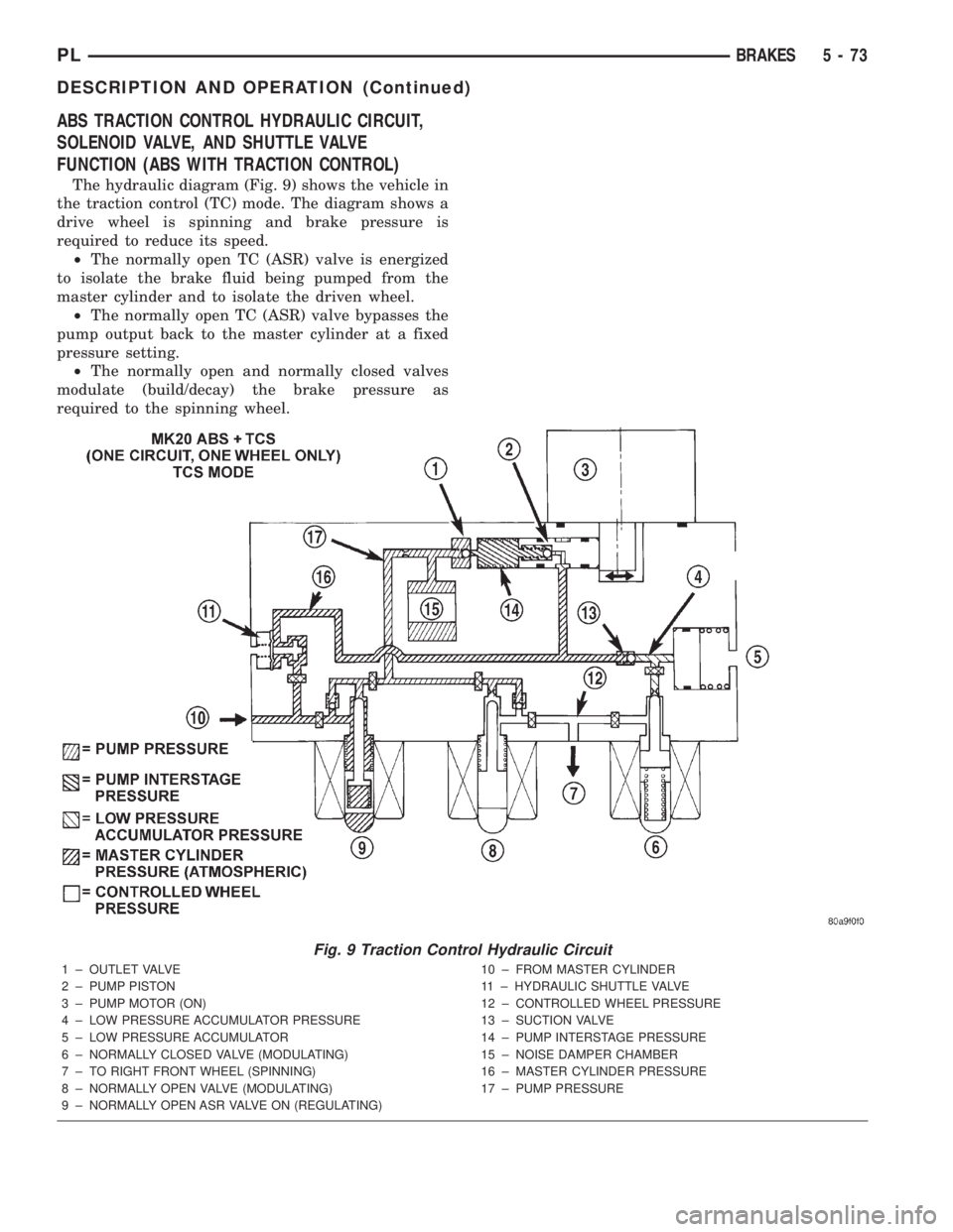
The hydraulic diagram (Fig. 9) shows the vehicle in
the traction control (TC) mode. The diagram shows a
drive wheel is spinning and brake pressure is
required to reduce its speed.
²The normally open TC (ASR) valve is energized
to isolate the brake fluid being pumped from the
master cylinder and to isolate the driven wheel.
²The normally open TC (ASR) valve bypasses the
pump output back to the master cylinder at a fixed
pressure setting.
²The normally open and normally closed valves
modulate (build/decay) the brake pressure as
required to the spinning wheel.
Fig. 9 Traction Control Hydraulic Circuit
1 ± OUTLET VALVE
2 ± PUMP PISTON
3 ± PUMP MOTOR (ON)
4 ± LOW PRESSURE ACCUMULATOR PRESSURE
5 ± LOW PRESSURE ACCUMULATOR
6 ± NORMALLY CLOSED VALVE (MODULATING)
7 ± TO RIGHT FRONT WHEEL (SPINNING)
8 ± NORMALLY OPEN VALVE (MODULATING)
9 ± NORMALLY OPEN ASR VALVE ON (REGULATING)10 ± FROM MASTER CYLINDER
11 ± HYDRAULIC SHUTTLE VALVE
12 ± CONTROLLED WHEEL PRESSURE
13 ± SUCTION VALVE
14 ± PUMP INTERSTAGE PRESSURE
15 ± NOISE DAMPER CHAMBER
16 ± MASTER CYLINDER PRESSURE
17 ± PUMP PRESSURE
PLBRAKES 5 - 73
DESCRIPTION AND OPERATION (Continued)
Page 153 of 1285
DIAGNOSIS AND TESTING
SERVICE WARNINGS AND CAUTIONS
The ABS uses an electronic control module, the
CAB. This module is designed to withstand normal
current draws associated with vehicle operation.
Care must be taken to avoid overloading the CAB
circuits.
CAUTION: In testing for open or short circuits, do
not ground or apply voltage to any of the circuits
unless instructed to do so for a diagnostic proce-
dure.
CAUTION: These circuits should only be tested
using a high impedance multi-meter or the DRB
scan tool as described in this section. Power
should never be removed or applied to any control
module with the ignition in the ON position. Before
removing or connecting battery cables, fuses, or
connectors, always turn the ignition to the OFF
position.
CAUTION: Use only factory wiring harnesses. Do
not cut or splice wiring to the brake circuits. The
addition of after-market electrical equipment (car
phone, radar detector, citizen band radio, trailer
lighting, trailer brakes, etc.) on a vehicle equipped
with antilock brakes may affect the function of the
antilock brake system.
ABS GENERAL DIAGNOSTICS INFORMATION
This section contains information necessary to
diagnose the antilock brake system. Specifically, this
section should be used to help diagnose conditions
which result in any of the following:
(1) amber ABS warning lamp turned on.
(2) brakes lock-up on hard application.
Diagnosis of base brake conditions that are obvi-
ously mechanical in nature should be directed to
BASE BRAKE SYSTEM at the beginning of this
group.
Many ABS conditions judged to be a problem by
the driver may be normal operating conditions. See
ABS OPERATION in the DESCRIPTION AND
OPERATION section of this group to become famil-
iarized with the normal characteristics of this
antilock brake system.
ABS WIRING DIAGRAM INFORMATION
During the diagnosis and testing of the antilock
brake system it may become necessary to reference
the wiring diagrams covering the antilock brake sys-
tem and its components. For wiring diagrams refer to
GROUP 8W of this service manual. It will provide
you with the wiring diagrams and the circuit descrip-
tion and operation information covering the antilock
brake system.
ABS VEHICLE TEST DRIVE
Most ABS complaints will require a test drive to
properly duplicate and diagnose the condition.
WARNING: CONDITIONS THAT RESULT IN TURN-
ING ON THE RED BRAKE WARNING LAMP MAY
INDICATE REDUCED BRAKING ABILITY.
Before test driving a brake complaint vehicle, note
whether the red BRAKE warning lamp, amber ABS
warning lamp, or both are turned on. If it is the red
BRAKE warning lamp, there is a brake hydraulic
problem that must be corrected before driving the
vehicle. Refer to the BASE BRAKE SYSTEM for
diagnosis of the red BRAKE warning lamp. If the red
brake warning lamp is illuminated, there is also a
possibility that there is an ABS problem and the
amber ABS warning lamp is not able to illuminate,
so the MIC turns on the red Brake warning lamp by
default.
If the amber ABS warning lamp is on, test drive
the vehicle as described below. While the amber ABS
warning lamp is on, the ABS is not functional. The
ability to stop the car using the base brake system
should not be affected.
If a functional problem of the ABS is determined
while test driving the vehicle, refer to the Chassis
Diagnostic Procedures manual.
(1) Turn the key to the OFF position and then
back to the ON position. Note whether the amber
ABS warning lamp continues to stay on. If it does,
refer to the diagnostic manual.
(2) If the amber ABS warning lamp goes out, shift
into gear and drive the car to a speed of 20 kph (12
mph) to complete the ABS start-up and drive-off
cycles (see ABS ELECTRONIC DIAGNOSIS). If at
this time the amber ABS warning lamp comes on,
refer to the diagnostic manual.
(3) If the amber ABS warning lamp remains out,
drive the vehicle a short distance. Accelerate the
vehicle to a speed of at least 40 mph. Bring the vehi-
cle to a complete stop, braking hard enough to cause
the ABS to cycle. Again accelerate the vehicle past 25
mph. Refer to the diagnostic manual for further test-
ing of the antilock brake system.
5 - 74 BRAKESPL
Page 155 of 1285
junction block. A label on the underside of the PDC
cover identifies the locations of the ABS fuses.
(2) Inspect the 25-way electrical connector at the
CAB for damaged, spread, or backed-out wiring ter-
minals. Verify that the 25-way connector is fully
inserted in the socket of the CAB. Be sure that wires
are not stretched tight or pulled out of the connector.
(3) Verify that all the wheel speed sensor connec-
tions are secure.
(4) Look for poor mating of connector halves or ter-
minals not fully seated in the connector body.
(5)
Check for improperly formed or damaged termi-
nals. All connector terminals in a suspect circuit should
be carefully reformed to increase contact tension.
(6) Look for poor terminal-to-wire connections.
This requires removing the terminal from the connec-
tor body to inspect it.
(7) Verify pin presence in the connector assembly
(8) Check for proper ground connections. Check all
ground connections for signs of corrosion, loose fas-
teners, or other potential defects. Refer to the wiring
diagrams for ground locations.
(9) Look for problems with the main power sources
of the vehicle. Inspect the battery, generator, ignition
circuits and other related relays and fuses.
If a visual check does not find the cause of the
problem, operate the car in an attempt to duplicate
the condition and record any trouble codes.
Most failures of the ABS disable the ABS function
for the entire ignition cycle even if the fault clears
before key-off. There are some failure conditions,
however, that allow ABS operation to resume during
the ignition cycle in which the trouble occurred even
if the trouble conditions are no longer present.
The following trouble conditions may result in
intermittent illumination of the amber ABS warning
lamp.
²Low system voltage. If Low System Voltage is
detected by the CAB, the CAB will turn on the ABS
Warning Lamp until normal system voltage is
achieved. Once normal voltage is seen at the CAB,
normal operation resumes.
²High system voltage. If high system voltage is
detected by the CAB, the CAB will turn on the
Amber ABS Warning Lamp until normal system volt-
age is achieved. Once normal voltage is again
detected by the CAB, normal ABS operation resumes.
Additional possible causes that may result in the
illumination of the amber ABS warning lamp are as
follows:
²Any condition that interrupts electrical current
to the CAB may cause the amber ABS warning lamp
to turn on intermittently.
²If PCI communication between the body control-
ler and the CAB is interrupted, the body controller
can turn on the amber ABS warning lamp.
TONE WHEEL
Tone wheels can cause erratic wheel speed sensor
signals. Inspect tone wheels for the following possible
causes:
²missing, chipped, or broken teeth
²contact with the wheel speed sensor
²wheel speed sensor to tone wheel alignment
²wheel speed sensor to tone wheel clearance
²excessive tone wheel runout
²tone wheel loose on its mounting surface
If a front tone wheel is found to need replacement,
the drive shaft must be replaced. No attempt should
be made to replace just the tone wheel. Refer to the
DIFFERENTIAL AND DRIVELINE group in this
service manual for removal and installation.
If a rear tone wheel is found to need replacement,
the rear hub and bearing must be replaced. No
attempt should be made to replace just the tone
wheel. Refer to the SUSPENSION group in this ser-
vice manual for removal and installation.
If wheel speed sensor to tone wheel contact is evi-
dent, determine the cause and correct it before
replacing the wheel speed sensor or tone wheel.
Check the gap between the speed sensor head and
the tone wheel to ensure it is within specifications.
Refer to SPECIFICATIONS in this section of the ser-
vice manual for the minimum and maximum wheel
speed sensor to tone wheel clearance.
Excessive wheel speed sensor runout can cause
erratic wheel speed sensor signals. Refer to SPECI-
FICATIONS in this section of the service manual for
the maximum allowed tone wheel runout. If tone
wheel runout is excessive, determine if it is caused
by a defect in the driveshaft assembly or hub and
bearing. Replace as necessary.
Tone wheels are pressed onto their mounting sur-
faces and should not rotate independently from the
mounting surface. Replacement of the front drive-
shaft or rear hub and bearing is necessary.
BRAKE FLUID CONTAMINATION
Indications of fluid contamination are swollen or
deteriorated rubber parts. Swelling indicates the
presence of petroleum in the brake fluid.
To test for contamination, put a small amount of
drained brake fluid in clear glass jar. If the fluid sep-
arates into layers, there is mineral oil or other fluid
contamination of the brake fluid.
If the brake fluid is contaminated, drain and thor-
oughly flush the brake system. Replace all the rubber
parts or components containing rubber coming into
contact with the brake fluid including: the master
cylinder; proportioning valves; caliper seals; wheel
cylinder seals; ABS hydraulic control unit; and all
hydraulic fluid hoses.
5 - 76 BRAKESPL
DIAGNOSIS AND TESTING (Continued)
Page 171 of 1285
the ignition key to the start position. The engine
starter should crank. If the starter does not crank,
visually inspect the clutch pedal for obstructions
(floor mat, etc.). Also make sure the clutch pedal
blade contacts and fully
Electrical Test
(1) Move ignition key to the ªOFF/LOCKº position
and remove key.
(2) Set park brake.
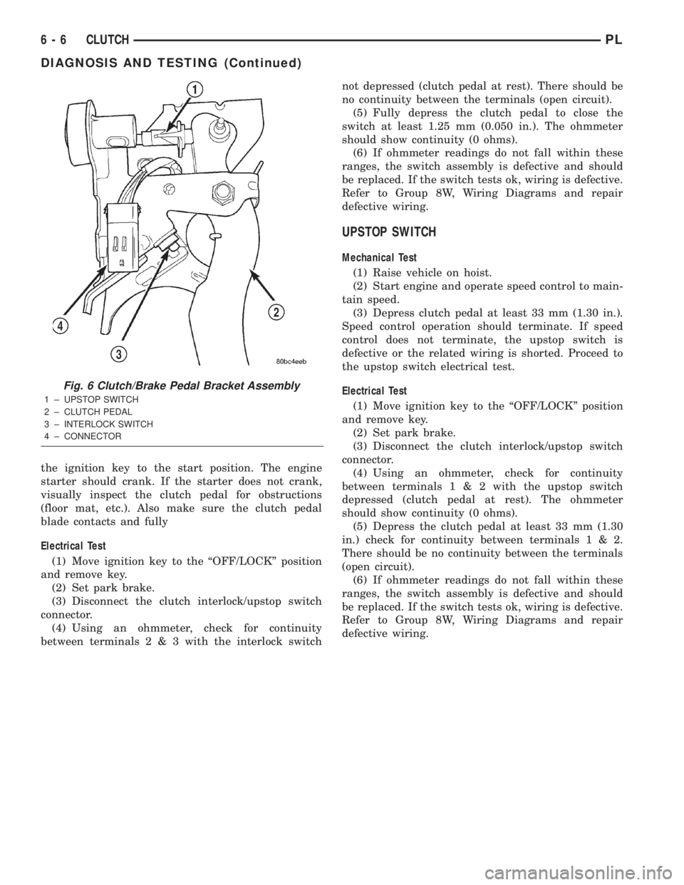
(3) Disconnect the clutch interlock/upstop switch
connector.
(4) Using an ohmmeter, check for continuity
between terminals2&3with the interlock switchnot depressed (clutch pedal at rest). There should be
no continuity between the terminals (open circuit).
(5) Fully depress the clutch pedal to close the
switch at least 1.25 mm (0.050 in.). The ohmmeter
should show continuity (0 ohms).
(6) If ohmmeter readings do not fall within these
ranges, the switch assembly is defective and should
be replaced. If the switch tests ok, wiring is defective.
Refer to Group 8W, Wiring Diagrams and repair
defective wiring.
UPSTOP SWITCH
Mechanical Test
(1) Raise vehicle on hoist.
(2) Start engine and operate speed control to main-
tain speed.
(3) Depress clutch pedal at least 33 mm (1.30 in.).
Speed control operation should terminate. If speed
control does not terminate, the upstop switch is
defective or the related wiring is shorted. Proceed to
the upstop switch electrical test.
Electrical Test
(1) Move ignition key to the ªOFF/LOCKº position
and remove key.
(2) Set park brake.
(3) Disconnect the clutch interlock/upstop switch
connector.
(4) Using an ohmmeter, check for continuity
between terminals1&2with the upstop switch
depressed (clutch pedal at rest). The ohmmeter
should show continuity (0 ohms).
(5) Depress the clutch pedal at least 33 mm (1.30
in.) check for continuity between terminals1&2.
There should be no continuity between the terminals
(open circuit).
(6) If ohmmeter readings do not fall within these
ranges, the switch assembly is defective and should
be replaced. If the switch tests ok, wiring is defective.
Refer to Group 8W, Wiring Diagrams and repair
defective wiring.
Fig. 6 Clutch/Brake Pedal Bracket Assembly
1 ± UPSTOP SWITCH
2 ± CLUTCH PEDAL
3 ± INTERLOCK SWITCH
4 ± CONNECTOR
6 - 6 CLUTCHPL
DIAGNOSIS AND TESTING (Continued)