2000 DODGE NEON diagram
[x] Cancel search: diagramPage 243 of 1285
CRANKSHAFT POSITION SENSOR
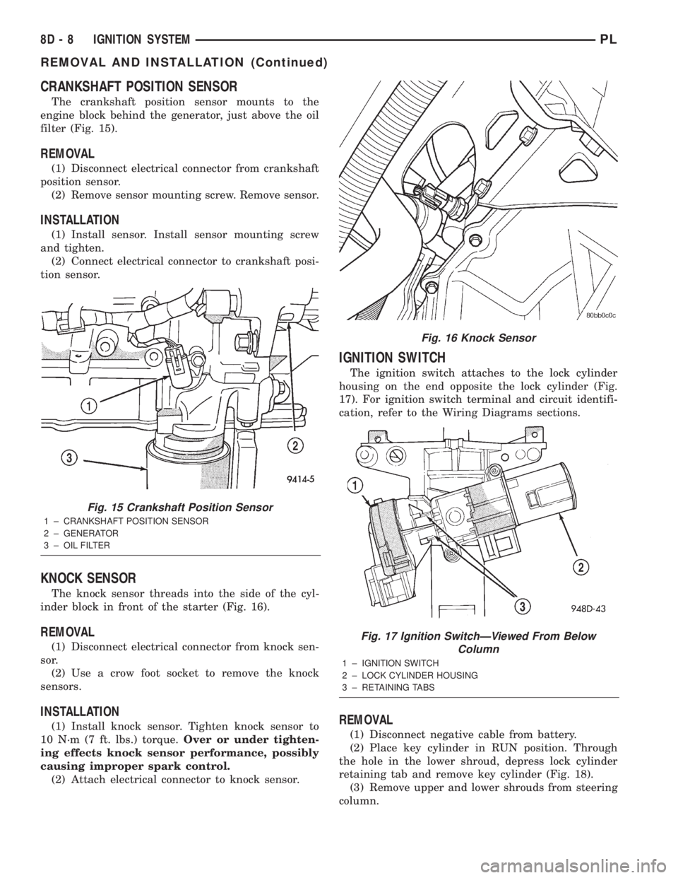
The crankshaft position sensor mounts to the
engine block behind the generator, just above the oil
filter (Fig. 15).
REMOVAL
(1) Disconnect electrical connector from crankshaft
position sensor.
(2) Remove sensor mounting screw. Remove sensor.
INSTALLATION
(1) Install sensor. Install sensor mounting screw
and tighten.
(2) Connect electrical connector to crankshaft posi-
tion sensor.
KNOCK SENSOR
The knock sensor threads into the side of the cyl-
inder block in front of the starter (Fig. 16).
REMOVAL
(1) Disconnect electrical connector from knock sen-
sor.
(2) Use a crow foot socket to remove the knock
sensors.
INSTALLATION
(1) Install knock sensor. Tighten knock sensor to
10 N´m (7 ft. lbs.) torque.Over or under tighten-
ing effects knock sensor performance, possibly
causing improper spark control.
(2) Attach electrical connector to knock sensor.
IGNITION SWITCH
The ignition switch attaches to the lock cylinder
housing on the end opposite the lock cylinder (Fig.
17). For ignition switch terminal and circuit identifi-
cation, refer to the Wiring Diagrams sections.
REMOVAL
(1) Disconnect negative cable from battery.
(2) Place key cylinder in RUN position. Through
the hole in the lower shroud, depress lock cylinder
retaining tab and remove key cylinder (Fig. 18).
(3) Remove upper and lower shrouds from steering
column.
Fig. 15 Crankshaft Position Sensor
1 ± CRANKSHAFT POSITION SENSOR
2 ± GENERATOR
3 ± OIL FILTER
Fig. 16 Knock Sensor
Fig. 17 Ignition SwitchÐViewed From Below
Column
1 ± IGNITION SWITCH
2 ± LOCK CYLINDER HOUSING
3 ± RETAINING TABS
8D - 8 IGNITION SYSTEMPL
REMOVAL AND INSTALLATION (Continued)
Page 257 of 1285
INSTRUMENT PANEL CENTER BEZEL
REMOVAL
(1) Remove HVAC control knobs from control head.
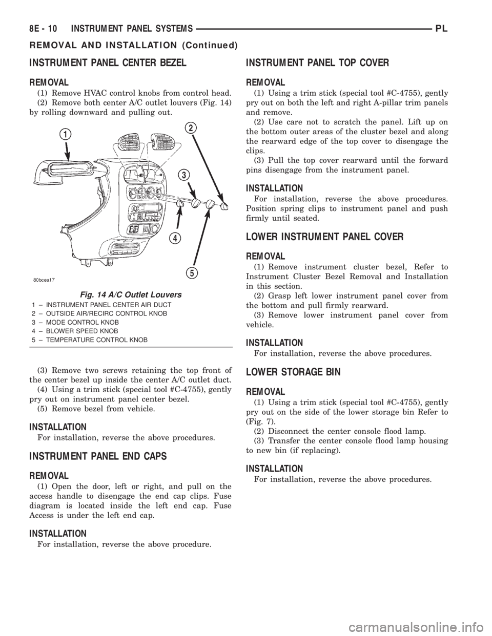
(2) Remove both center A/C outlet louvers (Fig. 14)
by rolling downward and pulling out.
(3) Remove two screws retaining the top front of
the center bezel up inside the center A/C outlet duct.
(4) Using a trim stick (special tool #C-4755), gently
pry out on instrument panel center bezel.
(5) Remove bezel from vehicle.
INSTALLATION
For installation, reverse the above procedures.
INSTRUMENT PANEL END CAPS
REMOVAL
(1) Open the door, left or right, and pull on the
access handle to disengage the end cap clips. Fuse
diagram is located inside the left end cap. Fuse
Access is under the left end cap.
INSTALLATION
For installation, reverse the above procedure.
INSTRUMENT PANEL TOP COVER
REMOVAL
(1) Using a trim stick (special tool #C-4755), gently
pry out on both the left and right A-pillar trim panels
and remove.
(2) Use care not to scratch the panel. Lift up on
the bottom outer areas of the cluster bezel and along
the rearward edge of the top cover to disengage the
clips.
(3) Pull the top cover rearward until the forward
pins disengage from the instrument panel.
INSTALLATION
For installation, reverse the above procedures.
Position spring clips to instrument panel and push
firmly until seated.
LOWER INSTRUMENT PANEL COVER
REMOVAL
(1) Remove instrument cluster bezel, Refer to
Instrument Cluster Bezel Removal and Installation
in this section.
(2) Grasp left lower instrument panel cover from
the bottom and pull firmly rearward.
(3) Remove lower instrument panel cover from
vehicle.
INSTALLATION
For installation, reverse the above procedures.
LOWER STORAGE BIN
REMOVAL
(1) Using a trim stick (special tool #C-4755), gently
pry out on the side of the lower storage bin Refer to
(Fig. 7).
(2) Disconnect the center console flood lamp.
(3) Transfer the center console flood lamp housing
to new bin (if replacing).
INSTALLATION
For installation, reverse the above procedures.
Fig. 14 A/C Outlet Louvers
1 ± INSTRUMENT PANEL CENTER AIR DUCT
2 ± OUTSIDE AIR/RECIRC CONTROL KNOB
3 ± MODE CONTROL KNOB
4 ± BLOWER SPEED KNOB
5 ± TEMPERATURE CONTROL KNOB
8E - 10 INSTRUMENT PANEL SYSTEMSPL
REMOVAL AND INSTALLATION (Continued)
Page 260 of 1285
INSTRUMENT PANEL AND SYSTEMS
TABLE OF CONTENTS
page page
DIAGNOSIS AND TESTING
HEADLAMP LEVELING SWITCH..............1
INSTRUMENT PANEL AND COMPONENTS.....1
REMOVAL AND INSTALLATION
HEADLAMP LEVELING SWITCH..............2INSTRUMENT PANEL ± R. H. D..............3
SPECIFICATIONS
TORQUE SPECIFICATIONS..................9
DIAGNOSIS AND TESTING
HEADLAMP LEVELING SWITCH
(1) Remove the headlamp leveling switch from the
instrument panel and disconnect the wire harness
connector from the switch. Refer to Wiring Diagrams
for the proper wire circuits and the wire connector
connections.
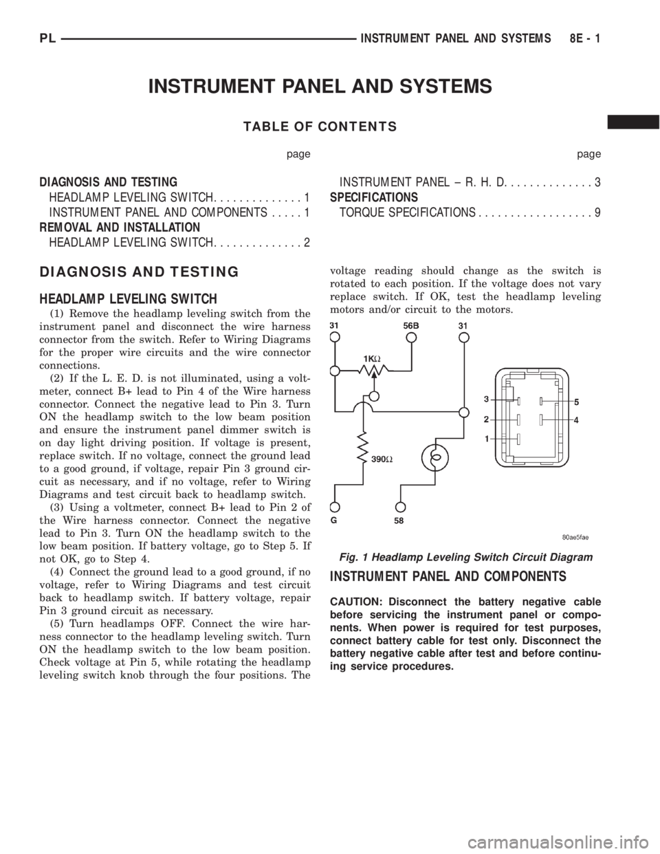
(2) If the L. E. D. is not illuminated, using a volt-
meter, connect B+ lead to Pin 4 of the Wire harness
connector. Connect the negative lead to Pin 3. Turn
ON the headlamp switch to the low beam position
and ensure the instrument panel dimmer switch is
on day light driving position. If voltage is present,
replace switch. If no voltage, connect the ground lead
to a good ground, if voltage, repair Pin 3 ground cir-
cuit as necessary, and if no voltage, refer to Wiring
Diagrams and test circuit back to headlamp switch.
(3) Using a voltmeter, connect B+ lead to Pin 2 of
the Wire harness connector. Connect the negative
lead to Pin 3. Turn ON the headlamp switch to the
low beam position. If battery voltage, go to Step 5. If
not OK, go to Step 4.
(4) Connect the ground lead to a good ground, if no
voltage, refer to Wiring Diagrams and test circuit
back to headlamp switch. If battery voltage, repair
Pin 3 ground circuit as necessary.
(5) Turn headlamps OFF. Connect the wire har-
ness connector to the headlamp leveling switch. Turn
ON the headlamp switch to the low beam position.
Check voltage at Pin 5, while rotating the headlamp
leveling switch knob through the four positions. Thevoltage reading should change as the switch is
rotated to each position. If the voltage does not vary
replace switch. If OK, test the headlamp leveling
motors and/or circuit to the motors.
INSTRUMENT PANEL AND COMPONENTS
CAUTION: Disconnect the battery negative cable
before servicing the instrument panel or compo-
nents. When power is required for test purposes,
connect battery cable for test only. Disconnect the
battery negative cable after test and before continu-
ing service procedures.
Fig. 1 Headlamp Leveling Switch Circuit Diagram
PLINSTRUMENT PANEL AND SYSTEMS 8E - 1
Page 270 of 1285
AUDIO SYSTEM
TABLE OF CONTENTS
page page
GENERAL INFORMATION
INTRODUCTION..........................1
DESCRIPTION AND OPERATION
INTERFERENCE ELIMINATION...............1
DIAGNOSIS AND TESTING
AUDIO DIAGNOSTIC TEST PROCEDURES......1
TESTING................................1
BENCH TEST FOR ANTENNA MALFUNCTION...7REMOVAL AND INSTALLATION
CD CHANGER............................7
FRONT DOOR SPEAKER....................8
INSTRUMENT PANEL SPEAKER(S)...........8
MAST and ANTENNA ASSEMBLY.............8
RADIO..................................9
REAR SHELF SPEAKER(S).................10
GENERAL INFORMATION
INTRODUCTION
Operating instructions for the factory installed
audio systems can be found in the Owner's Manual
provided with the vehicle.
The vehicles are equipped with an Interior (Igni-
tion Off Draw) fuse in the Power Distribution Center
located in the engine compartment. After the Interior
(IOD) fuse or battery has been disconnected the clock
will require resetting. The radio station presets have
a nonvolatile memory and will retain the preset sta-
tions after a battery disconnect.
The available radio options are:
²AM/FM Stereo Cassette w/Clock
²AM/FM/CD
²AM/FM Cassette w/CD Changer Controls and
Display
²CD/4 Disc Changer - In-Dash (used w/Radio CD
Changer Controls)
DESCRIPTION AND OPERATION
INTERFERENCE ELIMINATION
The radio utilizes a ground wire plugged on to a
blade terminal and is bolted to the radio chassis.
Both connector and terminal should be securely
attached. The engine has two separate ground straps
to suppress ignition noise which may interfere with
radio reception.
²Left engine mount clip on strap
²Engine to shock tower reinforcement
Inductive type spark plug cables in the high ten-
sion circuit of the ignition system complete the inter-
ference suppression. Faulty or deteriorated spark
plug wires should be replaced.
DIAGNOSIS AND TESTING
AUDIO DIAGNOSTIC TEST PROCEDURES
CAUTION: The CD player will only operate between
approximate temperatures of -23ÉC and +65ÉC (-10ÉF
and +145ÉF).
Whenever a radio malfunction occurs;
(1) First check FUSES:
(a) Power Distribution Center (PDC), Interior
lamp fuse, M1 - Radio Memory Feed
(b) Fuse Block:
(I) Fuse 12, Illumination in the fuse block
(II) Fuse 16, Ignition feed in the fuse block
NOTE: The vehicles are shipped with the INTERIOR
LAMP fuse disconnected.
(2) Verify, the radio wire harness are properly con-
nected before starting normal diagnosis and repair
procedures. Refer to Audio Diagnostic Charts and/or
Group 8W, Wiring Diagrams, Radio Section.
TESTING
The antenna has a short cable which connects into
the instrument panel harness. The connection is
made on the right side of the instrument panel.
Antenna performance may be tested by substitut-
ing a known good antenna. It is also possible to
check short or open circuits with an ohmmeter or
continuity light once the antenna cable is discon-
nected from the radio as follows:
(1) Continuity should be present between the
antenna mast and radio end pin of antenna cable
plug (Fig. 1).
(2) No continuity should be observed or a very
high resistance of several megohms between the
ground shell of the connector and radio end pin.
PLAUDIO SYSTEM 8F - 1
Page 280 of 1285
HORNS
TABLE OF CONTENTS
page page
DESCRIPTION AND OPERATION
INTRODUCTION..........................1
DIAGNOSIS AND TESTING
HORN..................................2
HORN RELAY............................2
HORN SWITCH...........................2HORN SYSTEM TEST......................2
REMOVAL AND INSTALLATION
HORN..................................4
HORN RELAY............................4
HORN SWITCH...........................5
DESCRIPTION AND OPERATION
INTRODUCTION
WARNING: ON VEHICLES EQUIPPED WITH AIR-
BAG, SEE GROUP 8M, PASSIVE RESTRAINT SYS-
TEMS FOR STEERING WHEEL REMOVAL.
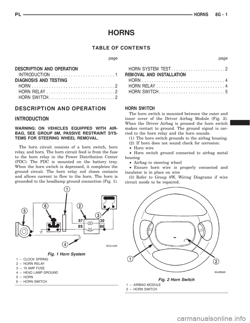
The horn circuit consists of a horn switch, horn
relay, and horn. The horn circuit feed is from the fuse
to the horn relay in the Power Distribution Center
(PDC). The PDC is mounted on the battery tray.
When the horn switch is depressed, it completes the
ground circuit. The horn relay coil closes contacts
and allows current to flow to the horn. The horn is
grounded to the headlamp ground connection (Fig. 1).
HORN SWITCH
The horn switch is mounted between the outer and
inner cover of the Driver Airbag Module (Fig. 2).
When the Driver Airbag is pressed the horn switch
makes contact to ground. The ground signal is car-
ried to the horn relay and the horn sounds.
(1) The horn switch grounds to the airbag housing.
(2) If horn does not sound check for corrosion:
²Horn wire
²Horn switch ground connected to airbag metal
housing
²Airbag to steering wheel
²Ensure horn wire is properly connected and
insulator is in place on wire
(3) Refer to Group 8W, Wiring Diagrams if wire
circuit needs to be repaired.
Fig. 1 Horn System
1 ± CLOCK SPRING
2 ± HORN RELAY
3 ± 15 AMP FUSE
4 ± HEAD LAMP GROUND
5 ± HORN
6 ± HORN SWITCH
Fig. 2 Horn Switch
1 ± AIRBAG MODULE
2 ± HORN SWITCH
PLHORNS 8G - 1
Page 281 of 1285
DIAGNOSIS AND TESTING
HORN
(1) Disconnect wire connector at horn.
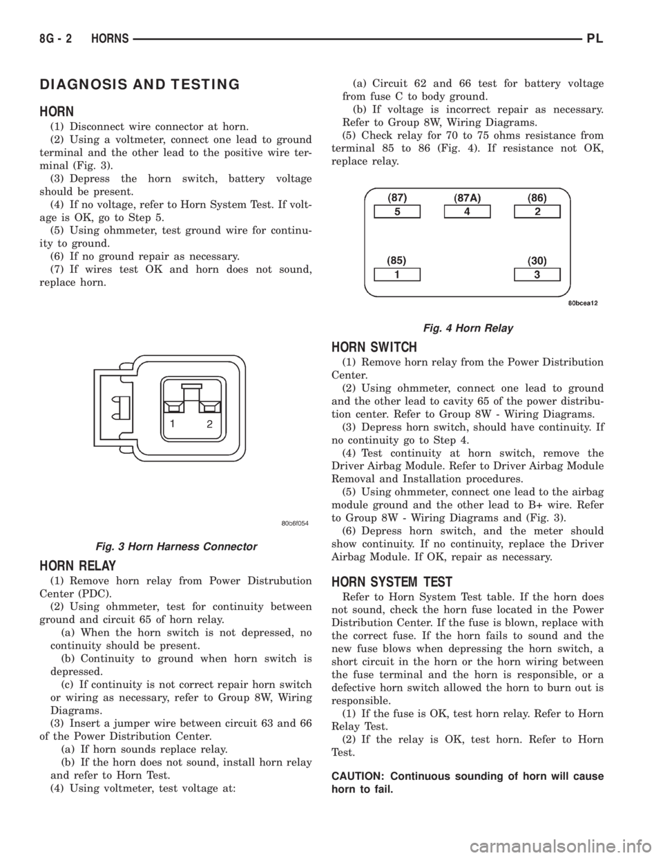
(2) Using a voltmeter, connect one lead to ground
terminal and the other lead to the positive wire ter-
minal (Fig. 3).
(3) Depress the horn switch, battery voltage
should be present.
(4) If no voltage, refer to Horn System Test. If volt-
age is OK, go to Step 5.
(5) Using ohmmeter, test ground wire for continu-
ity to ground.
(6) If no ground repair as necessary.
(7) If wires test OK and horn does not sound,
replace horn.
HORN RELAY
(1) Remove horn relay from Power Distrubution
Center (PDC).
(2) Using ohmmeter, test for continuity between
ground and circuit 65 of horn relay.
(a) When the horn switch is not depressed, no
continuity should be present.
(b) Continuity to ground when horn switch is
depressed.
(c) If continuity is not correct repair horn switch
or wiring as necessary, refer to Group 8W, Wiring
Diagrams.
(3) Insert a jumper wire between circuit 63 and 66
of the Power Distribution Center.
(a) If horn sounds replace relay.
(b) If the horn does not sound, install horn relay
and refer to Horn Test.
(4) Using voltmeter, test voltage at:(a) Circuit 62 and 66 test for battery voltage
from fuse C to body ground.
(b) If voltage is incorrect repair as necessary.
Refer to Group 8W, Wiring Diagrams.
(5) Check relay for 70 to 75 ohms resistance from
terminal 85 to 86 (Fig. 4). If resistance not OK,
replace relay.
HORN SWITCH
(1) Remove horn relay from the Power Distribution
Center.
(2) Using ohmmeter, connect one lead to ground
and the other lead to cavity 65 of the power distribu-
tion center. Refer to Group 8W - Wiring Diagrams.
(3) Depress horn switch, should have continuity. If
no continuity go to Step 4.
(4) Test continuity at horn switch, remove the
Driver Airbag Module. Refer to Driver Airbag Module
Removal and Installation procedures.
(5) Using ohmmeter, connect one lead to the airbag
module ground and the other lead to B+ wire. Refer
to Group 8W - Wiring Diagrams and (Fig. 3).
(6) Depress horn switch, and the meter should
show continuity. If no continuity, replace the Driver
Airbag Module. If OK, repair as necessary.
HORN SYSTEM TEST
Refer to Horn System Test table. If the horn does
not sound, check the horn fuse located in the Power
Distribution Center. If the fuse is blown, replace with
the correct fuse. If the horn fails to sound and the
new fuse blows when depressing the horn switch, a
short circuit in the horn or the horn wiring between
the fuse terminal and the horn is responsible, or a
defective horn switch allowed the horn to burn out is
responsible.
(1) If the fuse is OK, test horn relay. Refer to Horn
Relay Test.
(2) If the relay is OK, test horn. Refer to Horn
Test.
CAUTION: Continuous sounding of horn will cause
horn to fail.
Fig. 3 Horn Harness Connector
Fig. 4 Horn Relay
8G - 2 HORNSPL
Page 282 of 1285
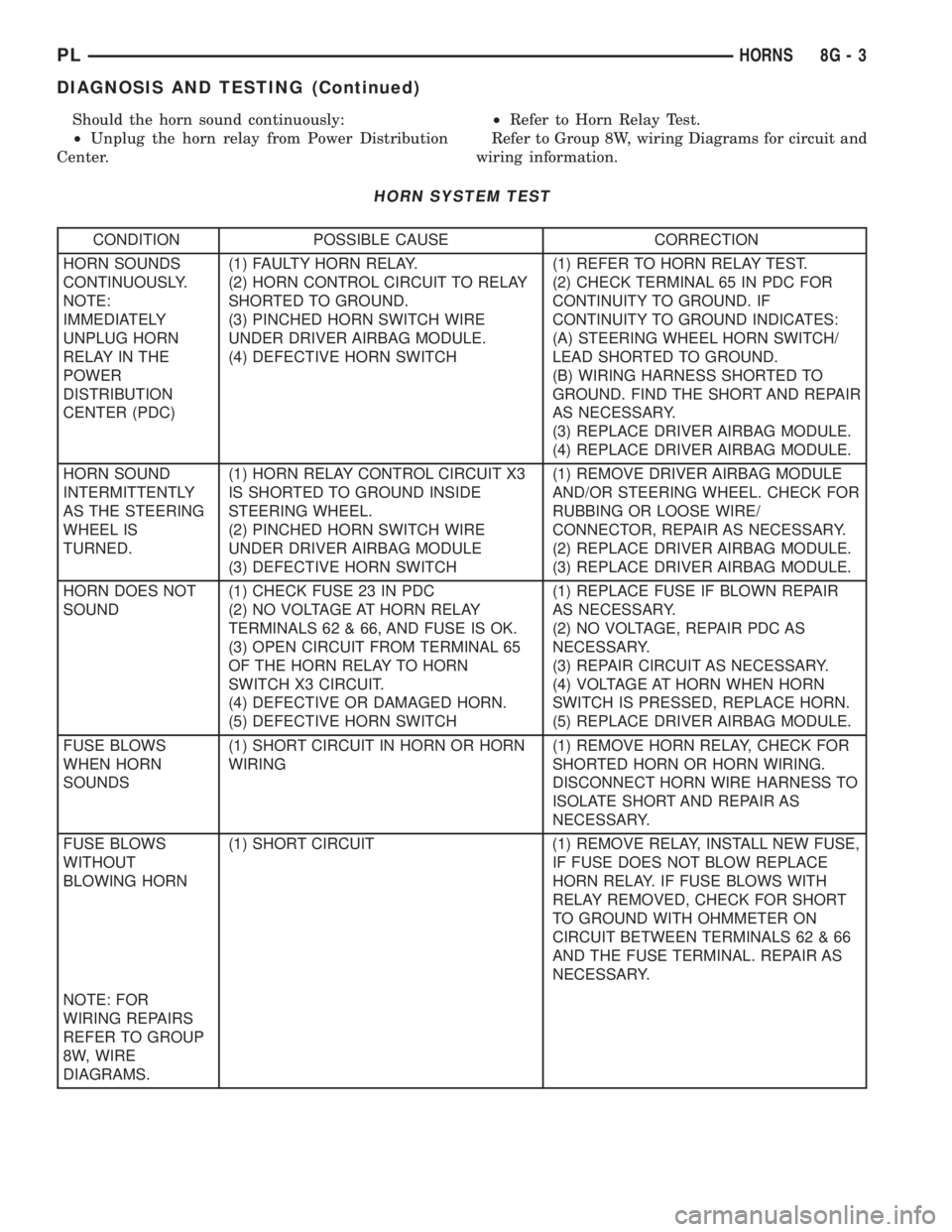
Should the horn sound continuously:
²Unplug the horn relay from Power Distribution
Center.²Refer to Horn Relay Test.
Refer to Group 8W, wiring Diagrams for circuit and
wiring information.
HORN SYSTEM TEST
CONDITION POSSIBLE CAUSE CORRECTION
HORN SOUNDS
CONTINUOUSLY.
NOTE:
IMMEDIATELY
UNPLUG HORN
RELAY IN THE
POWER
DISTRIBUTION
CENTER (PDC)(1) FAULTY HORN RELAY.
(2) HORN CONTROL CIRCUIT TO RELAY
SHORTED TO GROUND.
(3) PINCHED HORN SWITCH WIRE
UNDER DRIVER AIRBAG MODULE.
(4) DEFECTIVE HORN SWITCH(1) REFER TO HORN RELAY TEST.
(2) CHECK TERMINAL 65 IN PDC FOR
CONTINUITY TO GROUND. IF
CONTINUITY TO GROUND INDICATES:
(A) STEERING WHEEL HORN SWITCH/
LEAD SHORTED TO GROUND.
(B) WIRING HARNESS SHORTED TO
GROUND. FIND THE SHORT AND REPAIR
AS NECESSARY.
(3) REPLACE DRIVER AIRBAG MODULE.
(4) REPLACE DRIVER AIRBAG MODULE.
HORN SOUND
INTERMITTENTLY
AS THE STEERING
WHEEL IS
TURNED.(1) HORN RELAY CONTROL CIRCUIT X3
IS SHORTED TO GROUND INSIDE
STEERING WHEEL.
(2) PINCHED HORN SWITCH WIRE
UNDER DRIVER AIRBAG MODULE
(3) DEFECTIVE HORN SWITCH(1) REMOVE DRIVER AIRBAG MODULE
AND/OR STEERING WHEEL. CHECK FOR
RUBBING OR LOOSE WIRE/
CONNECTOR, REPAIR AS NECESSARY.
(2) REPLACE DRIVER AIRBAG MODULE.
(3) REPLACE DRIVER AIRBAG MODULE.
HORN DOES NOT
SOUND(1) CHECK FUSE 23 IN PDC
(2) NO VOLTAGE AT HORN RELAY
TERMINALS 62 & 66, AND FUSE IS OK.
(3) OPEN CIRCUIT FROM TERMINAL 65
OF THE HORN RELAY TO HORN
SWITCH X3 CIRCUIT.
(4) DEFECTIVE OR DAMAGED HORN.
(5) DEFECTIVE HORN SWITCH(1) REPLACE FUSE IF BLOWN REPAIR
AS NECESSARY.
(2) NO VOLTAGE, REPAIR PDC AS
NECESSARY.
(3) REPAIR CIRCUIT AS NECESSARY.
(4) VOLTAGE AT HORN WHEN HORN
SWITCH IS PRESSED, REPLACE HORN.
(5) REPLACE DRIVER AIRBAG MODULE.
FUSE BLOWS
WHEN HORN
SOUNDS(1) SHORT CIRCUIT IN HORN OR HORN
WIRING(1) REMOVE HORN RELAY, CHECK FOR
SHORTED HORN OR HORN WIRING.
DISCONNECT HORN WIRE HARNESS TO
ISOLATE SHORT AND REPAIR AS
NECESSARY.
FUSE BLOWS
WITHOUT
BLOWING HORN(1) SHORT CIRCUIT (1) REMOVE RELAY, INSTALL NEW FUSE,
IF FUSE DOES NOT BLOW REPLACE
HORN RELAY. IF FUSE BLOWS WITH
RELAY REMOVED, CHECK FOR SHORT
TO GROUND WITH OHMMETER ON
CIRCUIT BETWEEN TERMINALS 62 & 66
AND THE FUSE TERMINAL. REPAIR AS
NECESSARY.
NOTE: FOR
WIRING REPAIRS
REFER TO GROUP
8W, WIRE
DIAGRAMS.
PLHORNS 8G - 3
DIAGNOSIS AND TESTING (Continued)
Page 299 of 1285
DIAGNOSIS AND TESTING
WINDSHIELD WIPER CONDITIONS
WARNING: ON VEHICLES EQUIPPED WITH AIR-
BAGS, REFER TO GROUP 8M, PASSIVE
RESTRAINT SYSTEMS FOR STEERING WHEEL
REMOVAL AND INSTALLATION.
The following is a list of general wiper motor sys-
tem problems, the tests that are to be performed to
locate the faulty part, and the corrective action to be
taken.
Whatever the problem, disconnect motor wire har-
ness and clean the terminals, then connect motor
wire harness and test.
Refer to Group 8W Wiring Diagrams for circuit
information and connector call-outs.
MOTOR WILL NOT OPERATE IN SOME OR ALL
SWITCH POSITIONS
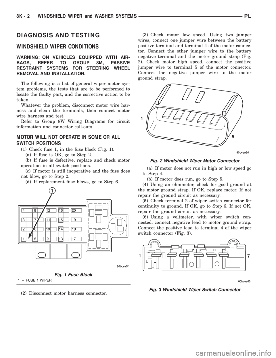
(1) Check fuse 1, in the fuse block (Fig. 1).
(a) If fuse is OK, go to Step 2.
(b) If fuse is defective, replace and check motor
operation in all switch positions.
(c) If motor is still inoperative and the fuse does
not blow, go to Step 2.
(d) If replacement fuse blows, go to Step 6.
(2) Disconnect motor harness connector.(3) Check motor low speed. Using two jumper
wires, connect one jumper wire between the battery
positive terminal and terminal 4 of the motor connec-
tor. Connect the other jumper wire to the battery
negative terminal and the motor ground strap (Fig.
2). Check motor high speed, connect the positive
jumper wire to terminal 5 of the motor connector.
Connect the negative jumper wire to the motor
ground strap.
(a) If motor does not run in high or low speed go
to Step 4.
(b) If motor does run, go to Step 5.
(4) Using an ohmmeter, check for good ground at
the motor ground strap. If OK, replace motor. If not
repair the ground circuit as necessary.
(5) Check terminal 2 of wiper switch connector for
continuity to ground. If OK, go to Step 6. If not OK,
repair the ground circuit as necessary.
(6) Using a voltmeter, with wiper switch con-
nected, connect negative lead to motor ground strap.
Connect the positive lead to terminal 4 of the wiper
switch connector (Fig. 3).
Fig. 1 Fuse Block
1 ± FUSE 1 WIPER
Fig. 2 Windshield Wiper Motor Connector
Fig. 3 Windshield Wiper Switch Connector
8K - 2 WINDSHIELD WIPER and WASHER SYSTEMSPL