2000 DODGE NEON diagram
[x] Cancel search: diagramPage 402 of 1285
²Connectors are fully seated
²Spread terminals, or terminal push out
²Terminals in the wiring assembly are fully
seated into the connector/component and locked in
position
²Dirt or corrosion on the terminals. Any amount
of corrosion or dirt could cause an intermittent prob-
lem
²Damaged connector/component casing exposing
the item to dirt and moisture
²Wire insulation that has rubbed through causing
a short to ground
²Some or all of the wiring strands broken inside
of the insulation covering
²Wiring broken inside of the insulation.
TROUBLESHOOTING TESTS
Before beginning any tests on a vehicles electrical
system use the Wiring Diagrams and study the cir-
cuit. Also refer to the Troubleshooting Wiring Prob-
lems in this section.
TESTING FOR VOLTAGE POTENTIAL
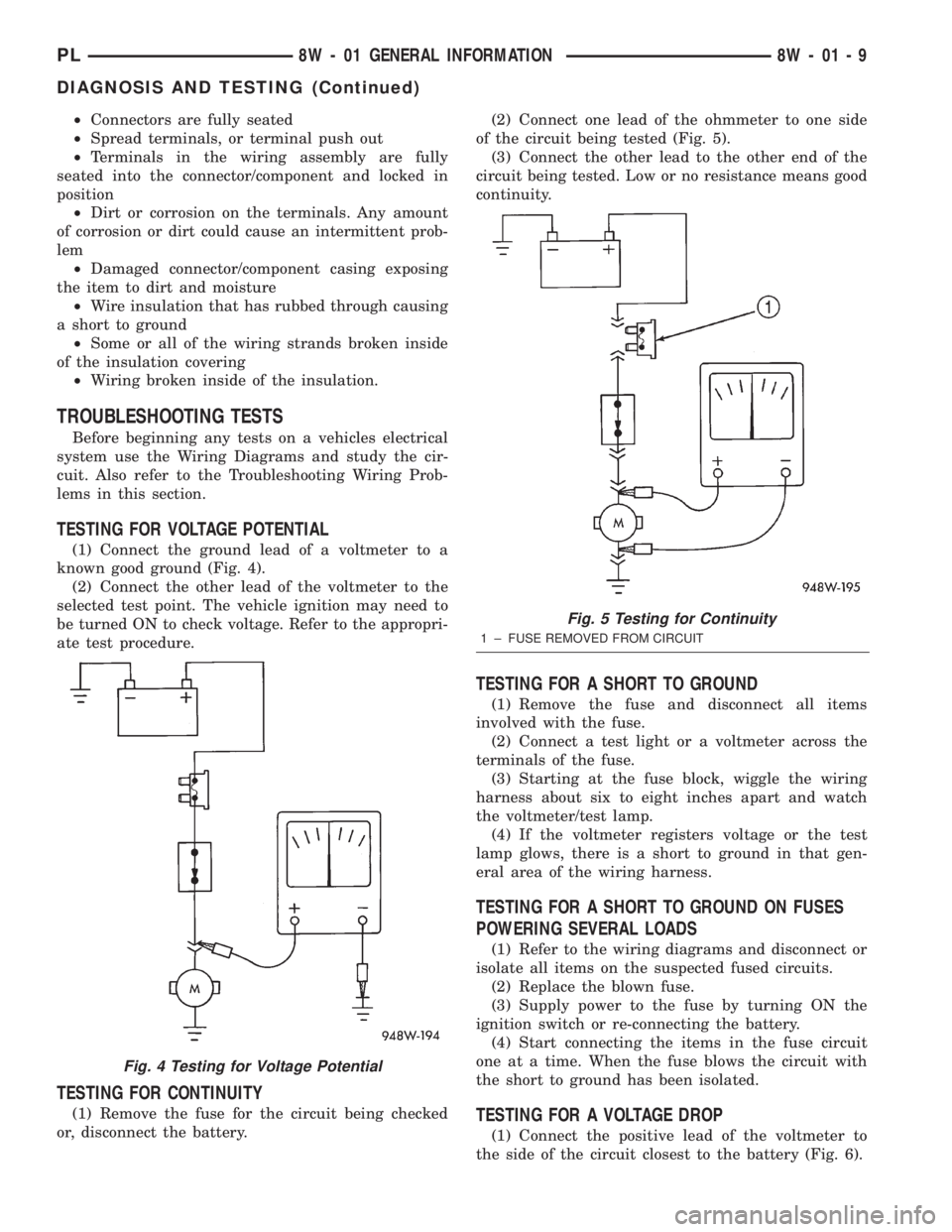
(1) Connect the ground lead of a voltmeter to a
known good ground (Fig. 4).
(2) Connect the other lead of the voltmeter to the
selected test point. The vehicle ignition may need to
be turned ON to check voltage. Refer to the appropri-
ate test procedure.
TESTING FOR CONTINUITY
(1) Remove the fuse for the circuit being checked
or, disconnect the battery.(2) Connect one lead of the ohmmeter to one side
of the circuit being tested (Fig. 5).
(3) Connect the other lead to the other end of the
circuit being tested. Low or no resistance means good
continuity.
TESTING FOR A SHORT TO GROUND
(1) Remove the fuse and disconnect all items
involved with the fuse.
(2) Connect a test light or a voltmeter across the
terminals of the fuse.
(3) Starting at the fuse block, wiggle the wiring
harness about six to eight inches apart and watch
the voltmeter/test lamp.
(4) If the voltmeter registers voltage or the test
lamp glows, there is a short to ground in that gen-
eral area of the wiring harness.
TESTING FOR A SHORT TO GROUND ON FUSES
POWERING SEVERAL LOADS
(1) Refer to the wiring diagrams and disconnect or
isolate all items on the suspected fused circuits.
(2) Replace the blown fuse.
(3) Supply power to the fuse by turning ON the
ignition switch or re-connecting the battery.
(4) Start connecting the items in the fuse circuit
one at a time. When the fuse blows the circuit with
the short to ground has been isolated.
TESTING FOR A VOLTAGE DROP
(1) Connect the positive lead of the voltmeter to
the side of the circuit closest to the battery (Fig. 6).
Fig. 4 Testing for Voltage Potential
Fig. 5 Testing for Continuity
1 ± FUSE REMOVED FROM CIRCUIT
PL8W - 01 GENERAL INFORMATION 8W - 01 - 9
DIAGNOSIS AND TESTING (Continued)
Page 403 of 1285
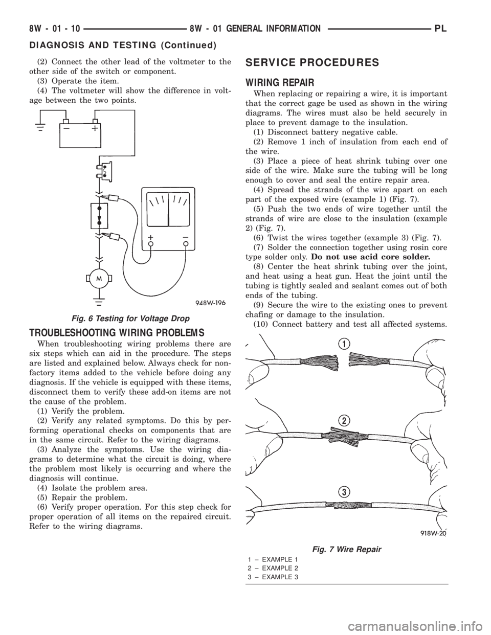
(2) Connect the other lead of the voltmeter to the
other side of the switch or component.
(3) Operate the item.
(4) The voltmeter will show the difference in volt-
age between the two points.
TROUBLESHOOTING WIRING PROBLEMS
When troubleshooting wiring problems there are
six steps which can aid in the procedure. The steps
are listed and explained below. Always check for non-
factory items added to the vehicle before doing any
diagnosis. If the vehicle is equipped with these items,
disconnect them to verify these add-on items are not
the cause of the problem.
(1) Verify the problem.
(2) Verify any related symptoms. Do this by per-
forming operational checks on components that are
in the same circuit. Refer to the wiring diagrams.
(3) Analyze the symptoms. Use the wiring dia-
grams to determine what the circuit is doing, where
the problem most likely is occurring and where the
diagnosis will continue.
(4) Isolate the problem area.
(5) Repair the problem.
(6) Verify proper operation. For this step check for
proper operation of all items on the repaired circuit.
Refer to the wiring diagrams.
SERVICE PROCEDURES
WIRING REPAIR
When replacing or repairing a wire, it is important
that the correct gage be used as shown in the wiring
diagrams. The wires must also be held securely in
place to prevent damage to the insulation.
(1) Disconnect battery negative cable.
(2) Remove 1 inch of insulation from each end of
the wire.
(3) Place a piece of heat shrink tubing over one
side of the wire. Make sure the tubing will be long
enough to cover and seal the entire repair area.
(4) Spread the strands of the wire apart on each
part of the exposed wire (example 1) (Fig. 7).
(5) Push the two ends of wire together until the
strands of wire are close to the insulation (example
2) (Fig. 7).
(6) Twist the wires together (example 3) (Fig. 7).
(7) Solder the connection together using rosin core
type solder only.Do not use acid core solder.
(8) Center the heat shrink tubing over the joint,
and heat using a heat gun. Heat the joint until the
tubing is tightly sealed and sealant comes out of both
ends of the tubing.
(9) Secure the wire to the existing ones to prevent
chafing or damage to the insulation.
(10) Connect battery and test all affected systems.
Fig. 6 Testing for Voltage Drop
Fig. 7 Wire Repair
1 ± EXAMPLE 1
2 ± EXAMPLE 2
3 ± EXAMPLE 3
8W - 01 - 10 8W - 01 GENERAL INFORMATIONPL
DIAGNOSIS AND TESTING (Continued)
Page 406 of 1285
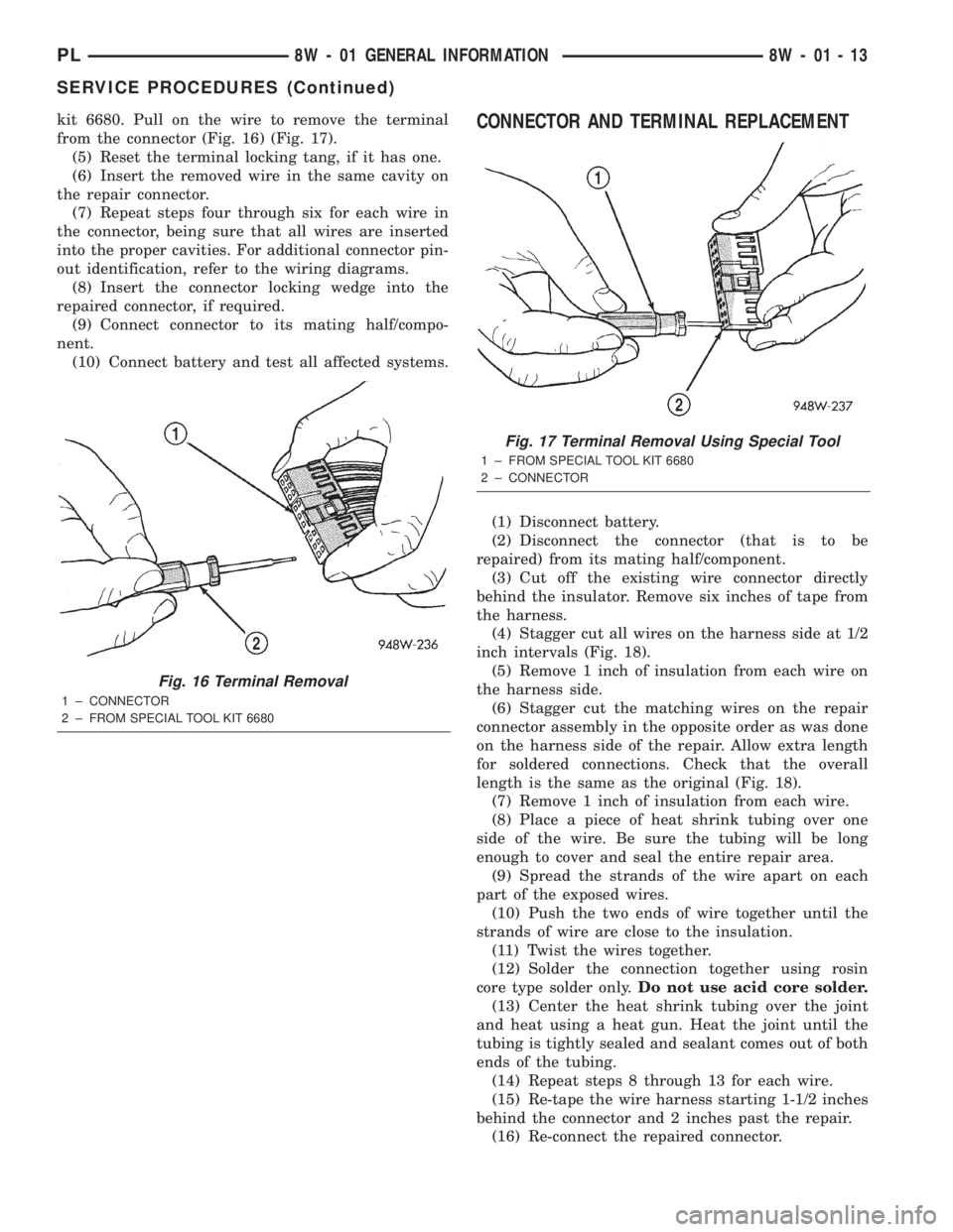
kit 6680. Pull on the wire to remove the terminal
from the connector (Fig. 16) (Fig. 17).
(5) Reset the terminal locking tang, if it has one.
(6) Insert the removed wire in the same cavity on
the repair connector.
(7) Repeat steps four through six for each wire in
the connector, being sure that all wires are inserted
into the proper cavities. For additional connector pin-
out identification, refer to the wiring diagrams.
(8) Insert the connector locking wedge into the
repaired connector, if required.
(9) Connect connector to its mating half/compo-
nent.
(10) Connect battery and test all affected systems.CONNECTOR AND TERMINAL REPLACEMENT
(1) Disconnect battery.
(2) Disconnect the connector (that is to be
repaired) from its mating half/component.
(3) Cut off the existing wire connector directly
behind the insulator. Remove six inches of tape from
the harness.
(4) Stagger cut all wires on the harness side at 1/2
inch intervals (Fig. 18).
(5) Remove 1 inch of insulation from each wire on
the harness side.
(6) Stagger cut the matching wires on the repair
connector assembly in the opposite order as was done
on the harness side of the repair. Allow extra length
for soldered connections. Check that the overall
length is the same as the original (Fig. 18).
(7) Remove 1 inch of insulation from each wire.
(8) Place a piece of heat shrink tubing over one
side of the wire. Be sure the tubing will be long
enough to cover and seal the entire repair area.
(9) Spread the strands of the wire apart on each
part of the exposed wires.
(10) Push the two ends of wire together until the
strands of wire are close to the insulation.
(11) Twist the wires together.
(12) Solder the connection together using rosin
core type solder only.Do not use acid core solder.
(13) Center the heat shrink tubing over the joint
and heat using a heat gun. Heat the joint until the
tubing is tightly sealed and sealant comes out of both
ends of the tubing.
(14) Repeat steps 8 through 13 for each wire.
(15) Re-tape the wire harness starting 1-1/2 inches
behind the connector and 2 inches past the repair.
(16) Re-connect the repaired connector.
Fig. 16 Terminal Removal
1 ± CONNECTOR
2 ± FROM SPECIAL TOOL KIT 6680
Fig. 17 Terminal Removal Using Special Tool
1 ± FROM SPECIAL TOOL KIT 6680
2 ± CONNECTOR
PL8W - 01 GENERAL INFORMATION 8W - 01 - 13
SERVICE PROCEDURES (Continued)
Page 408 of 1285
(11) Push the two ends of wire together until the
strands of wire are close to the insulation.
(12) Twist the wires together.
(13) Solder the connection together using rosin
core type solder only.Do not use acid core solder.
(14) Center the heat shrink tubing over the joint
and heat using a heat gun. Heat the joint until the
tubing is tightly sealed and sealant comes out of both
ends of the tubing.
(15) Insert the repaired wire into the connector.
(16) Install the connector locking wedge, if
required, and reconnect the connector to its mating
half/component.
(17) Re-tape the wire harness starting 1-1/2 inches
behind the connector and 2 inches past the repair.
(18) Connect battery, and test all affected systems.
DIODE REPLACEMENT
(1) Disconnect the battery.
(2) Locate the diode in the harness, and remove
the protective covering.
(3) Remove the diode from the harness, pay atten-
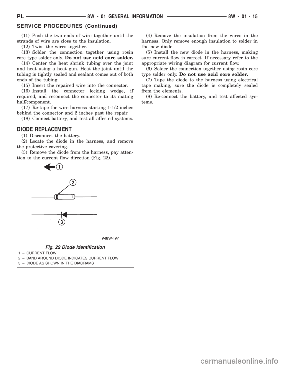
tion to the current flow direction (Fig. 22).(4) Remove the insulation from the wires in the
harness. Only remove enough insulation to solder in
the new diode.
(5) Install the new diode in the harness, making
sure current flow is correct. If necessary refer to the
appropriate wiring diagram for current flow.
(6) Solder the connection together using rosin core
type solder only.Do not use acid core solder.
(7) Tape the diode to the harness using electrical
tape making, sure the diode is completely sealed
from the elements.
(8) Re-connect the battery, and test affected sys-
tems.
Fig. 22 Diode Identification
1 ± CURRENT FLOW
2 ± BAND AROUND DIODE INDICATES CURRENT FLOW
3 ± DIODE AS SHOWN IN THE DIAGRAMS
PL8W - 01 GENERAL INFORMATION 8W - 01 - 15
SERVICE PROCEDURES (Continued)
Page 658 of 1285
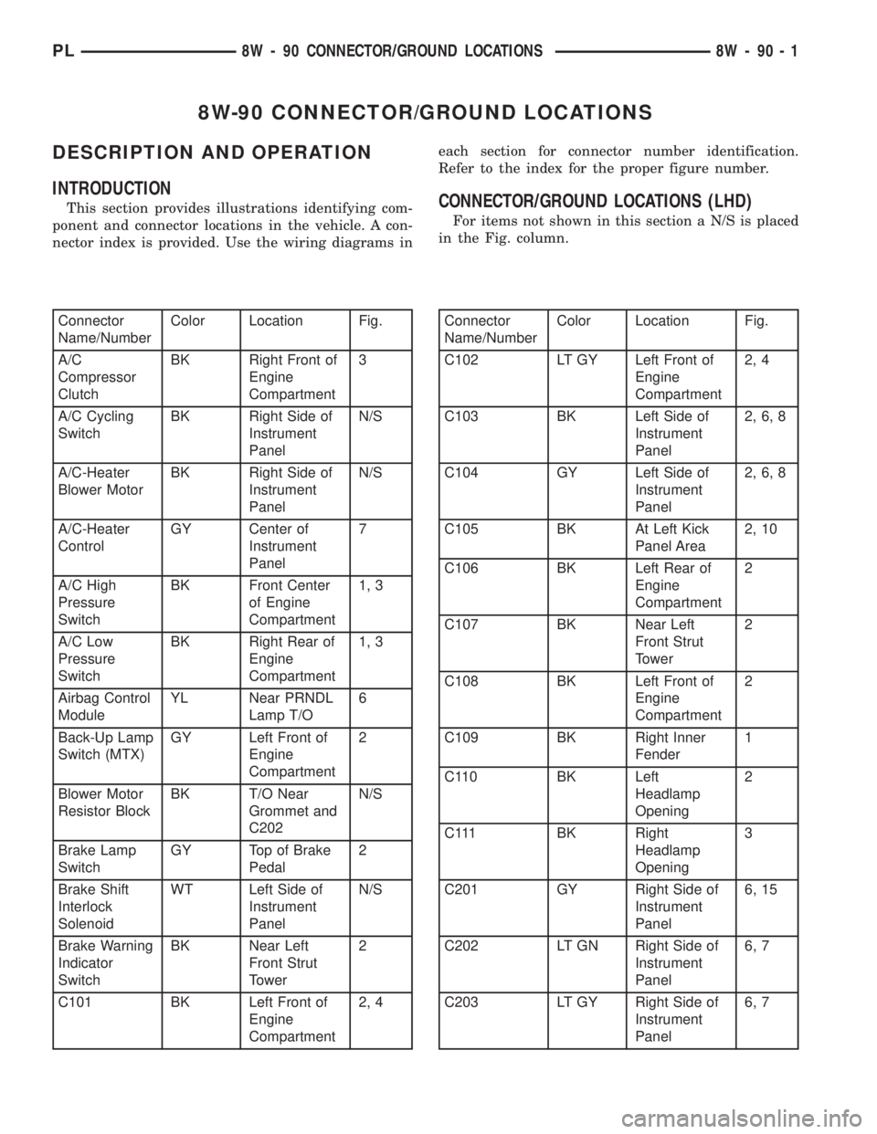
8W-90 CONNECTOR/GROUND LOCATIONS
DESCRIPTION AND OPERATION
INTRODUCTION
This section provides illustrations identifying com-
ponent and connector locations in the vehicle. A con-
nector index is provided. Use the wiring diagrams ineach section for connector number identification.
Refer to the index for the proper figure number.CONNECTOR/GROUND LOCATIONS (LHD)
For items not shown in this section a N/S is placed
in the Fig. column.
Connector
Name/NumberColor Location Fig.
A/C
Compressor
ClutchBK Right Front of
Engine
Compartment3
A/C Cycling
SwitchBK Right Side of
Instrument
PanelN/S
A/C-Heater
Blower MotorBK Right Side of
Instrument
PanelN/S
A/C-Heater
ControlGY Center of
Instrument
Panel7
A/C High
Pressure
SwitchBK Front Center
of Engine
Compartment1, 3
A/C Low
Pressure
SwitchBK Right Rear of
Engine
Compartment1, 3
Airbag Control
ModuleYL Near PRNDL
Lamp T/O6
Back-Up Lamp
Switch (MTX)GY Left Front of
Engine
Compartment2
Blower Motor
Resistor BlockBK T/O Near
Grommet and
C202N/S
Brake Lamp
SwitchGY Top of Brake
Pedal2
Brake Shift
Interlock
SolenoidWT Left Side of
Instrument
PanelN/S
Brake Warning
Indicator
SwitchBK Near Left
Front Strut
Tower2
C101 BK Left Front of
Engine
Compartment2, 4Connector
Name/NumberColor Location Fig.
C102 LT GY Left Front of
Engine
Compartment2, 4
C103 BK Left Side of
Instrument
Panel2, 6, 8
C104 GY Left Side of
Instrument
Panel2, 6, 8
C105 BK At Left Kick
Panel Area2, 10
C106 BK Left Rear of
Engine
Compartment2
C107 BK Near Left
Front Strut
Tower2
C108 BK Left Front of
Engine
Compartment2
C109 BK Right Inner
Fender1
C110 BK Left
Headlamp
Opening2
C111 BK Right
Headlamp
Opening3
C201 GY Right Side of
Instrument
Panel6, 15
C202 LT GN Right Side of
Instrument
Panel6, 7
C203 LT GY Right Side of
Instrument
Panel6, 7
PL8W - 90 CONNECTOR/GROUND LOCATIONS 8W - 90 - 1
Page 698 of 1285
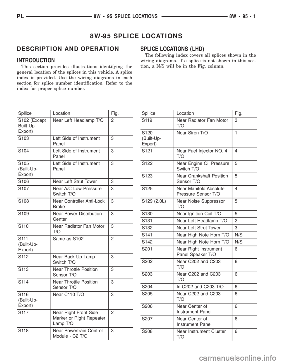
8W-95 SPLICE LOCATIONS
DESCRIPTION AND OPERATION
INTRODUCTION
This section provides illustrations identifying the
general location of the splices in this vehicle. A splice
index is provided. Use the wiring diagrams in each
section for splice number identification. Refer to the
index for proper splice number.
SPLICE LOCATIONS (LHD)
The following index covers all splices shown in the
wiring diagrams. If a splice is not shown in this sec-
tion, a N/S will be in the Fig. column.
Spllice Location Fig.
S102 (Except
Built-Up-
Export)Near Left Headlamp T/O 2
S103 Left Side of Instrument
Panel3
S104 Left Side of Instrument
Panel3
S105
(Built-Up-
Export)Left Side of Instrument
Panel3
S106 Near Left Strut Tower 3
S107 Near A/C Low Pressure
Switch T/O3
S108 Near Controller Anti-Lock
Brake3
S109 Near Power Distribution
Center3
S110 Near Radiator Fan Motor
T/O3
S 111
(Built-Up-
Export)Same as S102 2
S112 Near Back-Up Lamp
Switch T/O3
S113 Near Throttle Position
Sensor T/O3
S114 Near Throttle Position
Sensor T/O3
S116
(Built-Up-
Export)Near C110 T/O 3
S117 Near Right Front Side
Marker or Right Repeater
Lamp T/O2
S118 Near Powertrain Control
Module - C2 T/O3Spllice Location Fig.
S119 Near Radiator Fan Motor
T/O3
S120
(Built-Up-
Export)Near Siren T/O 1
S121 Near Fuel Injector NO. 4
T/O4
S122 Near Engine Oil Pressure
Switch T/O5
S123 Near Crankshaft Position
Sensor T/O5
S125 Near Manifold Absolute
Pressure Sensor T/O4
S129 (2.0L) Near Noise Suppressor
T/O5
S130 Near Ignition Coil T/O 5
S131 Near Left Headlamp T/O 2
S132 Near Left Strut Tower 3
S141 Near High Note Horn T/O N/S
S142 Near High Note Horn T/O N/S
S201 Near Right Instrument
Panel Speaker T/O6
S202 Near C202 and C203
T/O6
S203 Near C202 and C203
T/O6
S204 In C202 and C203 T/O 6
S205 Near C202 and C203
T/O6
S206 Near Center of
Instrument Panel6
S207 Near Center of
Instrument Panel6
S208 Near Instrument Cluster
T/O6
PL8W - 95 SPLICE LOCATIONS 8W - 95 - 1
Page 710 of 1285
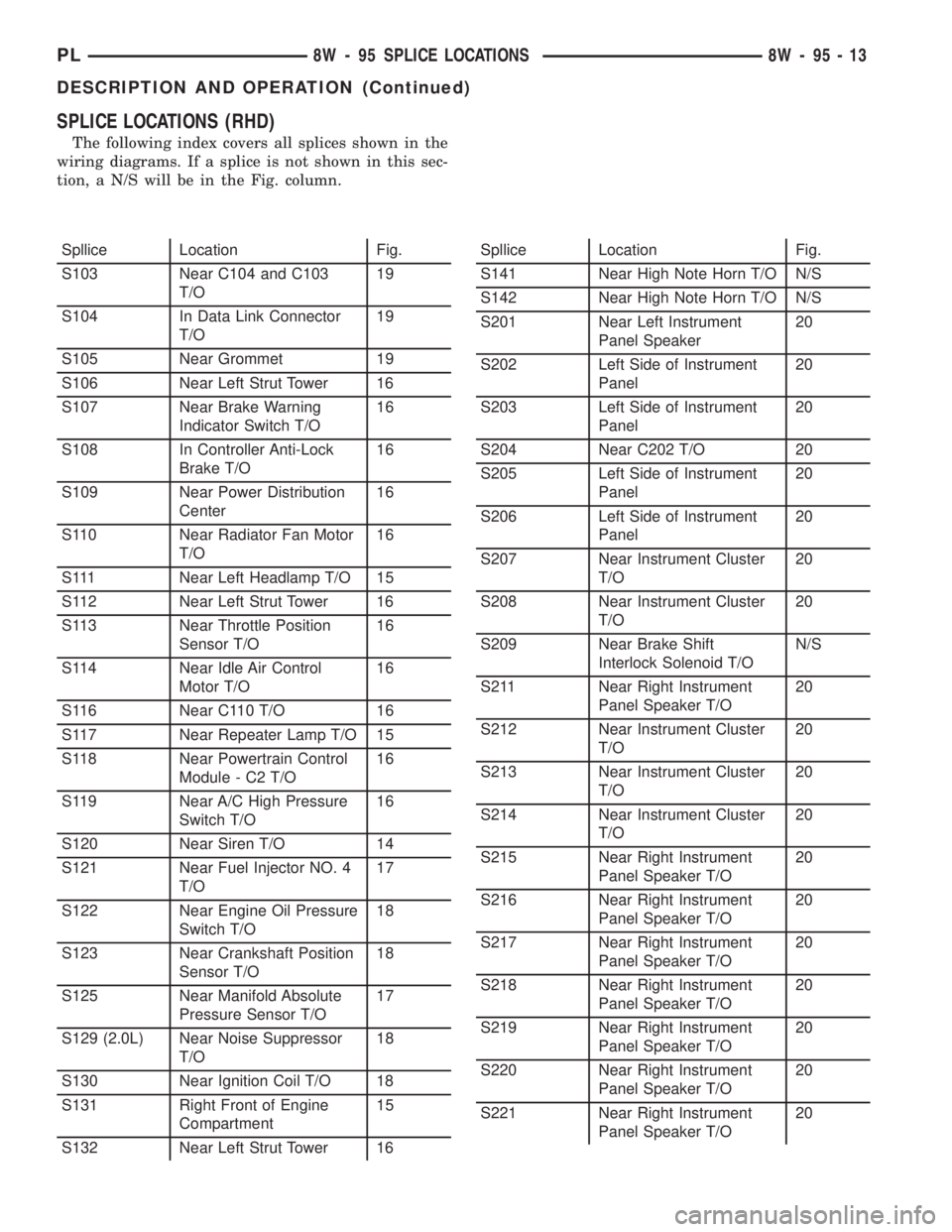
SPLICE LOCATIONS (RHD)
The following index covers all splices shown in the
wiring diagrams. If a splice is not shown in this sec-
tion, a N/S will be in the Fig. column.
Spllice Location Fig.
S103 Near C104 and C103
T/O19
S104 In Data Link Connector
T/O19
S105 Near Grommet 19
S106 Near Left Strut Tower 16
S107 Near Brake Warning
Indicator Switch T/O16
S108 In Controller Anti-Lock
Brake T/O16
S109 Near Power Distribution
Center16
S110 Near Radiator Fan Motor
T/O16
S111 Near Left Headlamp T/O 15
S112 Near Left Strut Tower 16
S113 Near Throttle Position
Sensor T/O16
S114 Near Idle Air Control
Motor T/O16
S116 Near C110 T/O 16
S117 Near Repeater Lamp T/O 15
S118 Near Powertrain Control
Module - C2 T/O16
S119 Near A/C High Pressure
Switch T/O16
S120 Near Siren T/O 14
S121 Near Fuel Injector NO. 4
T/O17
S122 Near Engine Oil Pressure
Switch T/O18
S123 Near Crankshaft Position
Sensor T/O18
S125 Near Manifold Absolute
Pressure Sensor T/O17
S129 (2.0L) Near Noise Suppressor
T/O18
S130 Near Ignition Coil T/O 18
S131 Right Front of Engine
Compartment15
S132 Near Left Strut Tower 16Spllice Location Fig.
S141 Near High Note Horn T/O N/S
S142 Near High Note Horn T/O N/S
S201 Near Left Instrument
Panel Speaker20
S202 Left Side of Instrument
Panel20
S203 Left Side of Instrument
Panel20
S204 Near C202 T/O 20
S205 Left Side of Instrument
Panel20
S206 Left Side of Instrument
Panel20
S207 Near Instrument Cluster
T/O20
S208 Near Instrument Cluster
T/O20
S209 Near Brake Shift
Interlock Solenoid T/ON/S
S211 Near Right Instrument
Panel Speaker T/O20
S212 Near Instrument Cluster
T/O20
S213 Near Instrument Cluster
T/O20
S214 Near Instrument Cluster
T/O20
S215 Near Right Instrument
Panel Speaker T/O20
S216 Near Right Instrument
Panel Speaker T/O20
S217 Near Right Instrument
Panel Speaker T/O20
S218 Near Right Instrument
Panel Speaker T/O20
S219 Near Right Instrument
Panel Speaker T/O20
S220 Near Right Instrument
Panel Speaker T/O20
S221 Near Right Instrument
Panel Speaker T/O20
PL8W - 95 SPLICE LOCATIONS 8W - 95 - 13
DESCRIPTION AND OPERATION (Continued)
Page 859 of 1285
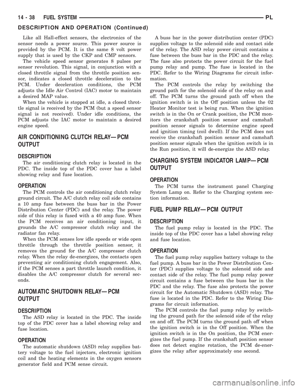
Like all Hall-effect sensors, the electronics of the
sensor needs a power source. This power source is
provided by the PCM. It is the same 8 volt power
supply that is used by the CKP and CMP sensors.
The vehicle speed sensor generates 8 pulses per
sensor revolution. This signal, in conjunction with a
closed throttle signal from the throttle position sen-
sor, indicates a closed throttle deceleration to the
PCM. Under deceleration conditions, the PCM
adjusts the Idle Air Control (IAC) motor to maintain
a desired MAP value.
When the vehicle is stopped at idle, a closed throt-
tle signal is received by the PCM (but a speed sensor
signal is not received). Under idle conditions, the
PCM adjusts the IAC motor to maintain a desired
engine speed.
AIR CONDITIONING CLUTCH RELAYÐPCM
OUTPUT
DESCRIPTION
The air conditioning clutch relay is located in the
PDC. The inside top of the PDC cover has a label
showing relay and fuse location.
OPERATION
The PCM controls the air conditioning clutch relay
ground circuit. The A/C clutch relay coil side contains
a 10 amp fuse between the buss bar in the Power
Distribution Center (PDC) and the relay. The power
side of this relay is fused with a 40 amp fuse. When
the PCM receives an air conditioning input, it
grounds the A/C compressor clutch relay and the
radiator fan relay.
When the PCM senses low idle speeds or wide open
throttle through the throttle position sensor, it
removes the ground for the A/C compressor clutch
relay. When the relay de-energizes, the contacts open
preventing air conditioning clutch engagement. Also,
if the PCM senses a part throttle launch condition, it
disables the A/C compressor clutch for several sec-
onds.
AUTOMATIC SHUTDOWN RELAYÐPCM
OUTPUT
DESCRIPTION
The ASD relay is located in the PDC. The inside
top of the PDC cover has a label showing relay and
fuse location.
OPERATION
The automatic shutdown (ASD) relay supplies bat-
tery voltage to the fuel injectors, electronic ignition
coil and the heating elements in the oxygen sensors
generator field and PCM sense circuit.A buss bar in the power distribution center (PDC)
supplies voltage to the solenoid side and contact side
of the relay. The ASD relay power circuit contains a
fuse between the buss bar in the PDC and the relay.
The fuse also protects the power circuit for the fuel
pump relay and pump. The fuse is located in the
PDC. Refer to the Wiring Diagrams for circuit infor-
mation.
The PCM controls the relay by switching the
ground path for the solenoid side of the relay on and
off. The PCM turns the ground path off when the
ignition switch is in the Off position unless the 02
Heater Monitor test is being run. When the ignition
switch is in the On or Crank position, the PCM mon-
itors the crankshaft position sensor and camshaft
position sensor signals to determine engine speed
and ignition timing (coil dwell). If the PCM does not
receive the crankshaft position sensor and camshaft
position sensor signals when the ignition switch is in
the Run position, it will de-energize the ASD relay.
CHARGING SYSTEM INDICATOR LAMPÐPCM
OUTPUT
OPERATION
The PCM turns the instrument panel Charging
System Lamp on. Refer to the Charging system sec-
tion information.
FUEL PUMP RELAYÐPCM OUTPUT
DESCRIPTION
The fuel pump relay is located in the PDC. The
inside top of the PDC cover has a label showing relay
and fuse location.
OPERATION
The fuel pump relay supplies battery voltage to the
fuel pump. A buss bar in the Power Distribution Cen-
ter (PDC) supplies voltage to the solenoid side and
contact side of the relay. The fuel pump relay power
circuit contains a fuse between the buss bar in the
PDC and the relay. The fuse also protects the power
circuit for the Automatic Shutdown (ASD) relay. The
fuse is located in the PDC. Refer to the Wiring Dia-
grams for circuit information.
The PCM controls the fuel pump relay by switch-
ing the ground path for the solenoid side of the relay
on and off. The PCM turns the ground path off when
the ignition switch is in the Off position. When the
ignition switch is in the On position, the PCM ener-
gizes the fuel pump. If the crankshaft position sensor
does not detect engine rotation, the PCM de-ener-
gizes the relay after approximately one second.
14 - 38 FUEL SYSTEMPL
DESCRIPTION AND OPERATION (Continued)