2000 DODGE NEON oxygen
[x] Cancel search: oxygenPage 750 of 1285
(8) Install lower engine torque strut. Refer to pro-
cedure in this section.
(9) Connect exhaust system to manifold. Refer to
Group 11, Exhaust System for procedure and torque
specifications.
(10) Connect the downstream oxygen sensor.
(11) Install A/C compressor and hoses. Refer to
Group 24, Heater and Air Conditioning for procedure.
(12) Install accessory drive belts. Refer to Group 7,
Cooling System Accessory Drive Section for belt ten-
sion adjustment.
(13) Install inner splash shield.
(14) Install wheels and lower vehicle.
(15) Install power steering pump and reservoir.
Refer to Group 7, Cooling System Accessory Drive
Section for belt tension adjustment.
(16)Manual Transmission:Connect clutch cable,
reverse light electrical connector and shift linkages.
Refer to Group 6, Clutch.
(17)Automatic Transmission:Connect shifter,
kickdown linkage and cooler lines. Refer to Group 21,
Transaxle for procedures.
(18) Connect fuel line and heater hoses.
(19)
Install all ground straps. Connect engine wiring
harness. Refer to Group 8, Electrical for procedure.
(20) Install lower radiator hose, fan module, and
upper radiator hose. Refer to Group 7, Cooling Sys-
tem for procedures
(21) Fill cooling system. Refer to Group 7, Cooling
System for filling procedure.
(22) Install battery tray and battery.
(23) Install air cleaner housing assembly and con-
nect intake duct to intake manifold.(24) Connect all throttle body electrical connectors
and linkage.
(25) Install oil filter. Fill engine crankcase with
proper oil to correct level.
(26) Perform camshaft and crankshaft timing
relearn procedure as follows:
²Connect the DRB scan tool to the data link
(diagnostic) connector. This connector is located in
the passenger compartment; at the lower edge of
instrument panel; near the steering column.
²Turn the ignition switch on and access the ªmis-
cellaneousº screen.
²Select ªre-learn cam/crankº option and follow
directions on DRB screen.
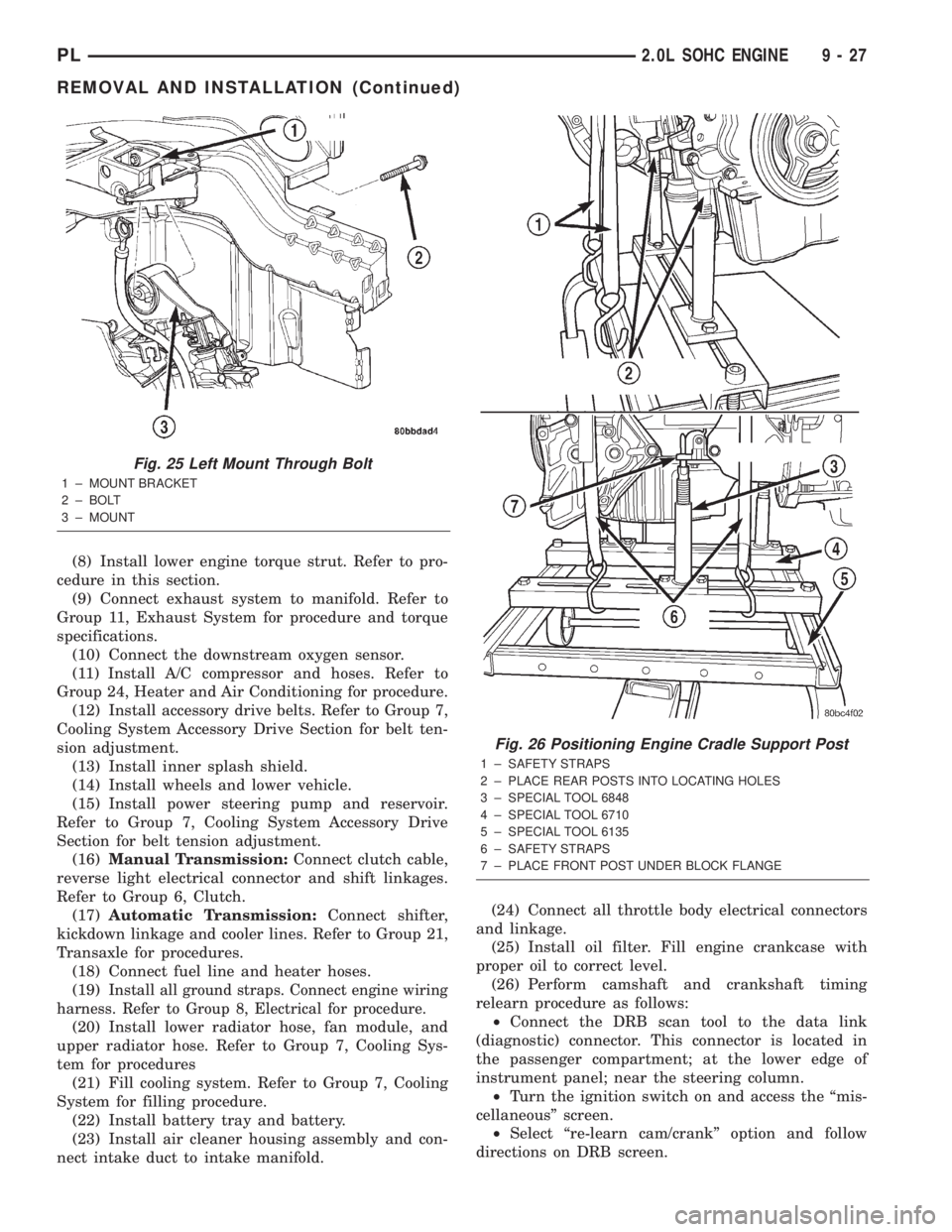
Fig. 25 Left Mount Through Bolt
1 ± MOUNT BRACKET
2 ± BOLT
3 ± MOUNT
Fig. 26 Positioning Engine Cradle Support Post
1 ± SAFETY STRAPS
2 ± PLACE REAR POSTS INTO LOCATING HOLES
3 ± SPECIAL TOOL 6848
4 ± SPECIAL TOOL 6710
5 ± SPECIAL TOOL 6135
6 ± SAFETY STRAPS
7 ± PLACE FRONT POST UNDER BLOCK FLANGE
PL2.0L SOHC ENGINE 9 - 27
REMOVAL AND INSTALLATION (Continued)
Page 753 of 1285
CAUTION: When using the ASD Fuel System Test,
the Auto Shutdown (ASD) relay will remain ener-
gized for 7 minutes or until the ignition switch is
turned to the OFF position, or Stop All Test is
selected.
EXHAUST MANIFOLD
REMOVAL
(1) Disconnect negative cable from battery.
(2) Raise vehicle on hoist.
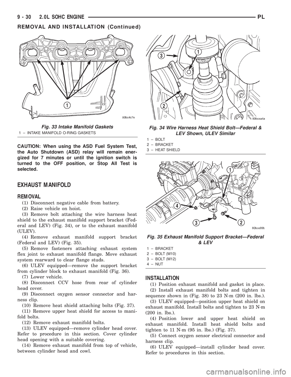
(3) Remove bolt attaching the wire harness heat
shield to the exhaust manifold support bracket (Fed-
eral and LEV) (Fig. 34), or to the exhaust manifold
(ULEV).
(4) Remove exhaust manifold support bracket
(Federal and LEV) (Fig. 35).
(5) Remove fasteners attaching exhaust system
flex joint to exhaust manifold flange. Move exhaust
system rearward to clear flange studs.
(6) ULEV equippedÐremove the support bracket
from cylinder block to exhaust manifold (Fig. 36).
(7) Lower vehicle.
(8) Disconnect CCV hose from rear of cylinder
head cover.
(9) Disconnect oxygen sensor connector and har-
ness clip.
(10) Remove heat shield attaching bolts (Fig. 37).
(11) Remove upper heat shield for access to mani-
fold bolts.
(12) Remove exhaust manifold bolts.
(13) ULEV equippedÐremove cylinder head cover.
Refer to procedure in this section. Cover cylinder
head opening with a suitable covering.
(14) Remove exhaust manifold from top of vehicle,
between cylinder head and cowl.
INSTALLATION
(1) Position exhaust manifold and gasket in place.
(2) Install exhaust manifold bolts and tighten in
sequence shown in (Fig. 38) to 23 N´m (200 in. lbs.).
(3) ULEV equippedÐposition upper heat shield on
exhaust manifold. Install bolts and tighten to 23 N´m
(200 in. lbs.).
(4) Position lower and upper heat shield on
exhaust manifold. Install heat shield bolts and
tighten to 11 N´m (95 in. lbs.) (Fig. 37).
(5) Connect oxygen sensor electrical connector and
harness clip.
(6) ULEV equippedÐinstall cylinder head cover.
Refer to procedures in this section.
Fig. 33 Intake Manifold Gaskets
1 ± INTAKE MANIFOLD O-RING GASKETS
Fig. 34 Wire Harness Heat Shield BoltÐFederal &
LEV Shown, ULEV Similar
1 ± BOLT
2 ± BRACKET
3 ± HEAT SHIELD
Fig. 35 Exhaust Manifold Support BracketÐFederal
& LEV
1 ± BRACKET
2 ± BOLT (M10)
3 ± BOLT (M12)
4 ± NUT
9 - 30 2.0L SOHC ENGINEPL
REMOVAL AND INSTALLATION (Continued)
Page 799 of 1285
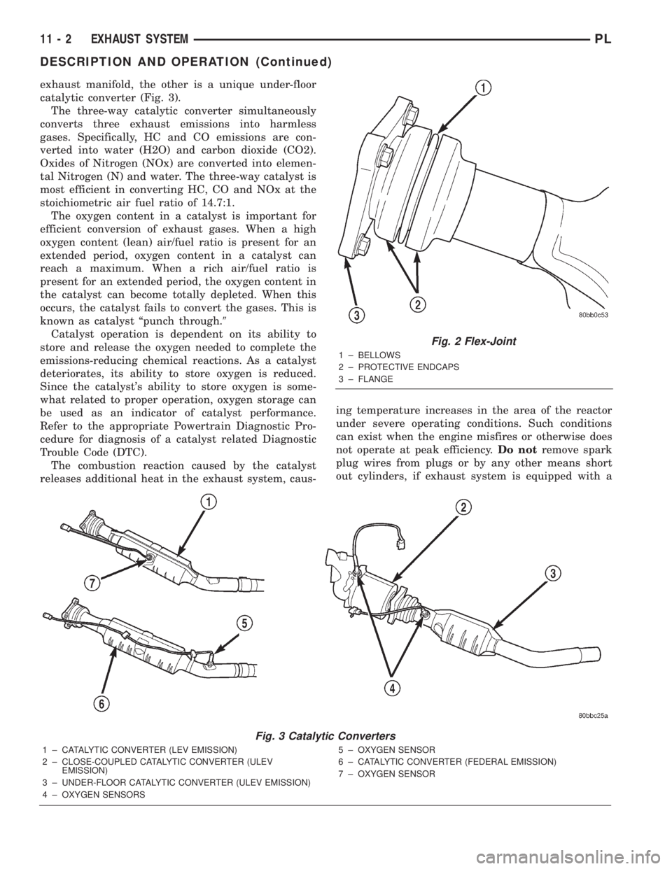
exhaust manifold, the other is a unique under-floor
catalytic converter (Fig. 3).
The three-way catalytic converter simultaneously
converts three exhaust emissions into harmless
gases. Specifically, HC and CO emissions are con-
verted into water (H2O) and carbon dioxide (CO2).
Oxides of Nitrogen (NOx) are converted into elemen-
tal Nitrogen (N) and water. The three-way catalyst is
most efficient in converting HC, CO and NOx at the
stoichiometric air fuel ratio of 14.7:1.
The oxygen content in a catalyst is important for
efficient conversion of exhaust gases. When a high
oxygen content (lean) air/fuel ratio is present for an
extended period, oxygen content in a catalyst can
reach a maximum. When a rich air/fuel ratio is
present for an extended period, the oxygen content in
the catalyst can become totally depleted. When this
occurs, the catalyst fails to convert the gases. This is
known as catalyst ªpunch through.9
Catalyst operation is dependent on its ability to
store and release the oxygen needed to complete the
emissions-reducing chemical reactions. As a catalyst
deteriorates, its ability to store oxygen is reduced.
Since the catalyst's ability to store oxygen is some-
what related to proper operation, oxygen storage can
be used as an indicator of catalyst performance.
Refer to the appropriate Powertrain Diagnostic Pro-
cedure for diagnosis of a catalyst related Diagnostic
Trouble Code (DTC).
The combustion reaction caused by the catalyst
releases additional heat in the exhaust system, caus-ing temperature increases in the area of the reactor
under severe operating conditions. Such conditions
can exist when the engine misfires or otherwise does
not operate at peak efficiency.Do notremove spark
plug wires from plugs or by any other means short
out cylinders, if exhaust system is equipped with a
Fig. 2 Flex-Joint
1 ± BELLOWS
2 ± PROTECTIVE ENDCAPS
3 ± FLANGE
Fig. 3 Catalytic Converters
1 ± CATALYTIC CONVERTER (LEV EMISSION)
2 ± CLOSE-COUPLED CATALYTIC CONVERTER (ULEV
EMISSION)
3 ± UNDER-FLOOR CATALYTIC CONVERTER (ULEV EMISSION)
4 ± OXYGEN SENSORS5 ± OXYGEN SENSOR
6 ± CATALYTIC CONVERTER (FEDERAL EMISSION)
7 ± OXYGEN SENSOR
11 - 2 EXHAUST SYSTEMPL
DESCRIPTION AND OPERATION (Continued)
Page 804 of 1285
CATALYTIC CONVERTER
REMOVAL
WARNING: THE NORMAL OPERATING TEMPERA-
TURE OF THE EXHAUST SYSTEM IS VERY HIGH.
THEREFORE, NEVER ATTEMPT TO SERVICE ANY
PART OF THE EXHAUST SYSTEM UNTIL IT IS
COOLED. SPECIAL CARE SHOULD BE TAKEN
WHEN WORKING NEAR THE CATALYTIC CON-
VERTER. THE TEMPERATURE OF THE CONVERTER
RISES TO A HIGH LEVEL AFTER A SHORT PERIOD
OF ENGINE OPERATION TIME.
NOTE: Vehicles equipped with the ULEV emission
package are equipped with an additional catalytic
converter that is integral to the exhaust manifold.
Refer to Exhaust Manifold in Group 9, Engine for
procedure.
(1) Remove muffler and exhaust pipe. Refer to pro-
cedure in this section.
(2) Disconnect downstream oxygen sensor electri-
cal connector.
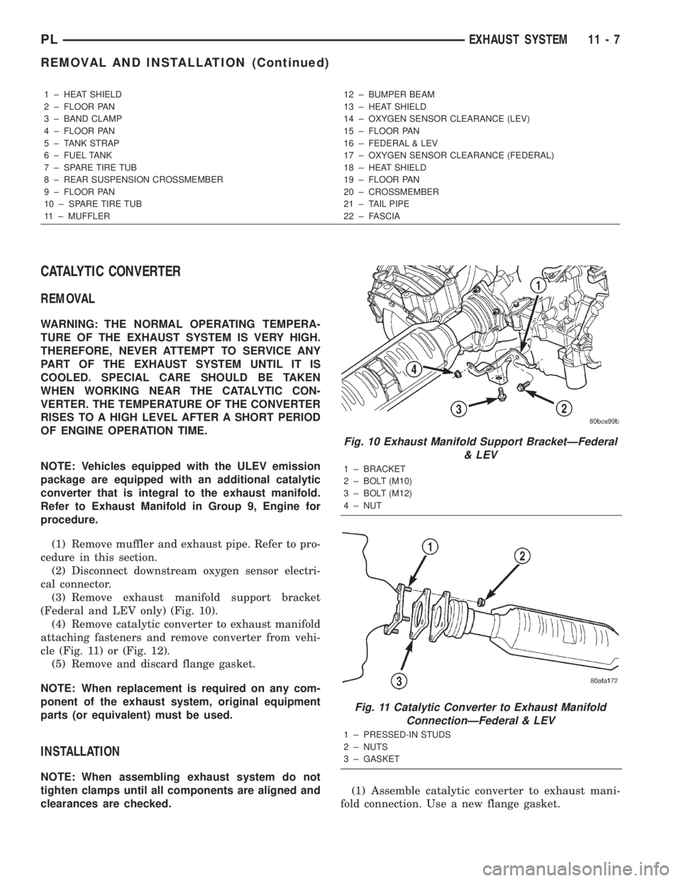
(3) Remove exhaust manifold support bracket
(Federal and LEV only) (Fig. 10).
(4) Remove catalytic converter to exhaust manifold
attaching fasteners and remove converter from vehi-
cle (Fig. 11) or (Fig. 12).
(5) Remove and discard flange gasket.
NOTE: When replacement is required on any com-
ponent of the exhaust system, original equipment
parts (or equivalent) must be used.
INSTALLATION
NOTE: When assembling exhaust system do not
tighten clamps until all components are aligned and
clearances are checked.(1) Assemble catalytic converter to exhaust mani-
fold connection. Use a new flange gasket.
1 ± HEAT SHIELD
2 ± FLOOR PAN
3 ± BAND CLAMP
4 ± FLOOR PAN
5 ± TANK STRAP
6 ± FUEL TANK
7 ± SPARE TIRE TUB
8 ± REAR SUSPENSION CROSSMEMBER
9 ± FLOOR PAN
10 ± SPARE TIRE TUB
11 ± MUFFLER12 ± BUMPER BEAM
13 ± HEAT SHIELD
14 ± OXYGEN SENSOR CLEARANCE (LEV)
15 ± FLOOR PAN
16 ± FEDERAL & LEV
17 ± OXYGEN SENSOR CLEARANCE (FEDERAL)
18 ± HEAT SHIELD
19 ± FLOOR PAN
20 ± CROSSMEMBER
21 ± TAIL PIPE
22 ± FASCIA
Fig. 10 Exhaust Manifold Support BracketÐFederal
& LEV
1 ± BRACKET
2 ± BOLT (M10)
3 ± BOLT (M12)
4 ± NUT
Fig. 11 Catalytic Converter to Exhaust Manifold
ConnectionÐFederal & LEV
1 ± PRESSED-IN STUDS
2 ± NUTS
3 ± GASKET
PLEXHAUST SYSTEM 11 - 7
REMOVAL AND INSTALLATION (Continued)
Page 805 of 1285
(2) Install exhaust manifold support bracket (Fed-
eral and LEV only). Tighten M10 bolt to 54 N´m (40
ft. lbs.), M12 bolt to 95 N´m (70 ft. lbs.), and nut to
28 N´m (250 in. lbs.).
(3) Install bolt attaching manifold support bracket
to the heat shield (Federal and LEV only). Tighten
bolt to 28 N´m (250 in. lbs.).
(4) Assemble muffler and exhaust pipe to catalytic
converter. Install muffler and pipe support isolators
to the underbody.
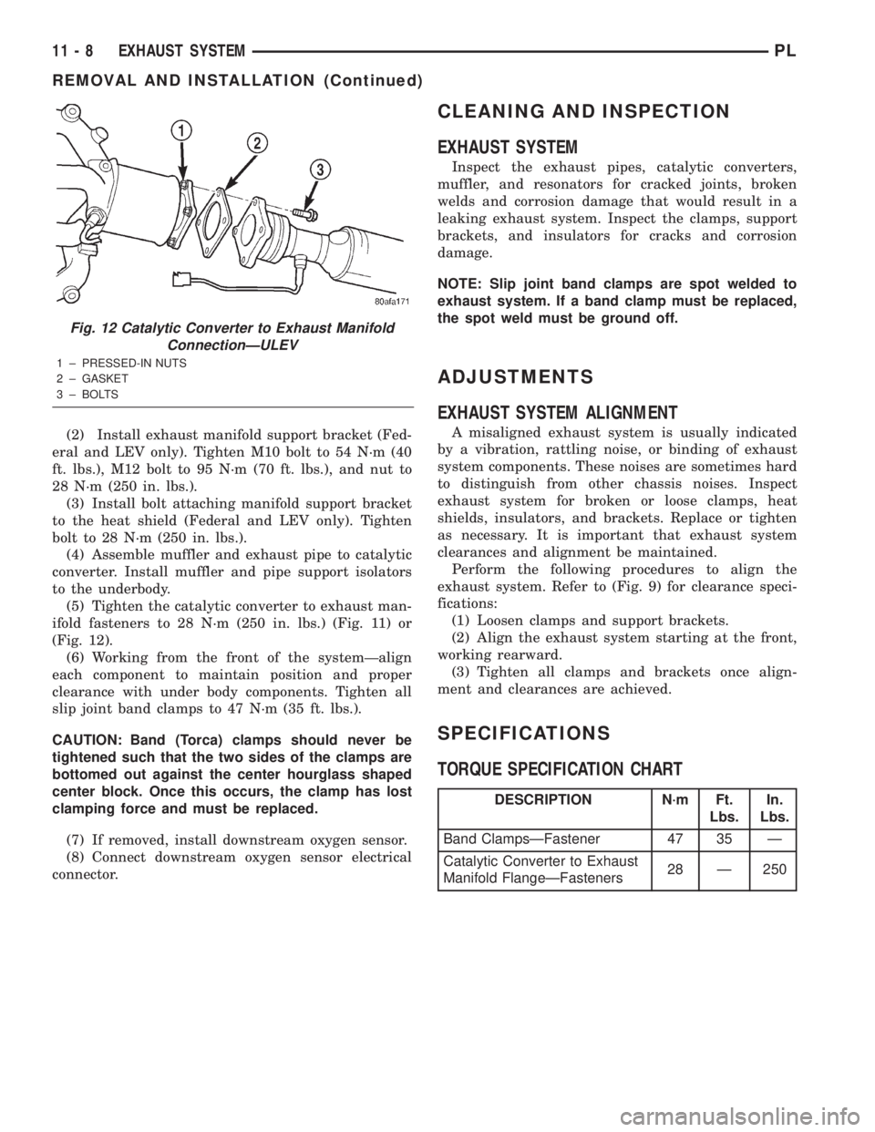
(5) Tighten the catalytic converter to exhaust man-
ifold fasteners to 28 N´m (250 in. lbs.) (Fig. 11) or
(Fig. 12).
(6) Working from the front of the systemÐalign
each component to maintain position and proper
clearance with under body components. Tighten all
slip joint band clamps to 47 N´m (35 ft. lbs.).
CAUTION: Band (Torca) clamps should never be
tightened such that the two sides of the clamps are
bottomed out against the center hourglass shaped
center block. Once this occurs, the clamp has lost
clamping force and must be replaced.
(7) If removed, install downstream oxygen sensor.
(8) Connect downstream oxygen sensor electrical
connector.
CLEANING AND INSPECTION
EXHAUST SYSTEM
Inspect the exhaust pipes, catalytic converters,
muffler, and resonators for cracked joints, broken
welds and corrosion damage that would result in a
leaking exhaust system. Inspect the clamps, support
brackets, and insulators for cracks and corrosion
damage.
NOTE: Slip joint band clamps are spot welded to
exhaust system. If a band clamp must be replaced,
the spot weld must be ground off.
ADJUSTMENTS
EXHAUST SYSTEM ALIGNMENT
A misaligned exhaust system is usually indicated
by a vibration, rattling noise, or binding of exhaust
system components. These noises are sometimes hard
to distinguish from other chassis noises. Inspect
exhaust system for broken or loose clamps, heat
shields, insulators, and brackets. Replace or tighten
as necessary. It is important that exhaust system
clearances and alignment be maintained.
Perform the following procedures to align the
exhaust system. Refer to (Fig. 9) for clearance speci-
fications:
(1) Loosen clamps and support brackets.
(2) Align the exhaust system starting at the front,
working rearward.
(3) Tighten all clamps and brackets once align-
ment and clearances are achieved.
SPECIFICATIONS
TORQUE SPECIFICATION CHART
Fig. 12 Catalytic Converter to Exhaust Manifold
ConnectionÐULEV
1 ± PRESSED-IN NUTS
2 ± GASKET
3 ± BOLTS
DESCRIPTION N´m Ft.
Lbs.In.
Lbs.
Band ClampsÐFastener 47 35 Ð
Catalytic Converter to Exhaust
Manifold FlangeÐFasteners28 Ð 250
11 - 8 EXHAUST SYSTEMPL
REMOVAL AND INSTALLATION (Continued)
Page 822 of 1285
FUEL SYSTEM
TABLE OF CONTENTS
page page
FUEL DELIVERY SYSTEM.................... 1FUEL INJECTION SYSTEM.................. 21
FUEL DELIVERY SYSTEM
TABLE OF CONTENTS
page page
DESCRIPTION AND OPERATION
FUEL REQUIREMENTS.....................1
GASOLINE/OXYGENATE BLENDS.............2
FUEL DELIVERY SYSTEM...................3
FUEL PUMP MODULE......................3
ELECTRIC FUEL PUMP.....................4
FUEL GAUGE SENDING UNIT................4
FUEL FILTER/FUEL PRESSURE REGULATOR....4
FUEL TANK..............................4
FUEL RAIL...............................4
FUEL INJECTORS.........................5
PRESSURE-VACUUM FILLER CAP............5
ONBOARD REFUELING VAPOR RECOVERY....6
CONTROL VALVE/PRESSURE RELIEF.........6
QUICK-CONNECT FITTINGS.................6
ROLLOVER VALVES.......................7
FUEL TUBES/LINES/HOSES AND CLAMPS......8
SERVICE PROCEDURES
FUEL SYSTEM PRESSURE RELEASE
PROCEDURE...........................8INJECTOR CONNECTOR....................8
DRAINING FUEL TANK.....................9
HOSES AND CLAMPS......................9
QUICK-CONNECT FITTINGS.................9
REMOVAL AND INSTALLATION
AUTOMATIC SHUTDOWN RELAY............12
FUEL PUMP RELAY.......................12
FUEL PUMP MODULE.....................12
FUEL FILTER / PRESSURE REGULATOR......13
FUEL PUMP INLET STRAINER..............14
FUEL LEVEL SENSOR.....................14
FUEL INJECTORS........................15
FUEL TANK.............................16
FUEL FILLER NECK.......................17
ACCELERATOR PEDAL....................18
THROTTLE CABLE.......................19
SPECIFICATIONS
TORQUE...............................20
DESCRIPTION AND OPERATION
FUEL REQUIREMENTS
OPERATION
Your engine is designed to meet all emissions reg-
ulations and provide excellent fuel economy and per-
formance when using high quality unleaded gasoline
having an octane rating of 87. The use of premium
gasoline is not recommended. The use of premium
gasoline will provide no benefit over high quality reg-
ular gasoline, and in some circumstances may result
in poorer performance.
Light spark knock at low engine speeds is not
harmful to your engine. However, continued heavyspark knock at high speeds can cause damage and
immediate service is required. Engine damage result-
ing from operation with a heavy spark knock may
not be covered by the new vehicle warranty.
Poor quality gasoline can cause problems such as
hard starting, stalling and hesitations. If you experi-
ence these symptoms, try another brand of gasoline
before considering service for the vehicle.
The American Automobile Manufacturers Associa-
tion, AAMA, has issued gasoline specifications to
define the minimum fuel properties necessary to
deliver enhanced performance and durability for your
vehicle. DaimlerChrysler Corporation recommends
the use of gasoline that meet the AAMA specifica-
tions if they are available.
PLFUEL SYSTEM 14 - 1
Page 823 of 1285
REFORMULATED GASOLINE
Many areas of the country require the use of
cleaner burning gasoline referred to as ªreformulat-
edº gasoline. Reformulated gasoline contain oxygen-
ates, and are specifically blended to reduce vehicle
emissions and improve air quality.
DaimlerChrysler Corporation strongly supports the
use of reformulated gasoline. Properly blended refor-
mulated gasoline will provide excellent performance
and durability for the engine and fuel system compo-
nents.
GASOLINE/OXYGENATE BLENDS
Some fuel suppliers blend unleaded gasoline with
oxygenates such as 10% ethanol, MTBE, and ETBE.
Oxygenates are required in some areas of the country
during the winter months to reduce carbon monoxide
emissions. Fuels blended with these oxygenates may
be used in your vehicle.
CAUTION: DO NOT use gasoline containing METH-
ANOL. Gasoline containing methanol may damage
critical fuel system components.
MMT
MMT is a manganese-containing metallic additive
that is blended into some gasoline to increase octane.
Gasoline blended with MMT provide no performance
advantage beyond gasoline of the same octane num-
ber without MMT. Gasoline blended with MMT
reduce spark plug life and reduce emission system
performance in some vehicles. DaimlerChrysler rec-
ommends that gasoline without MMT be used in your
vehicle. The MMT content of gasoline may not be
indicated on the gasoline pump; therefore, you should
ask your gasoline retailer whether or not his/her gas-
oline contains MMT.
It is even more important to look for gasoline with-
out MMT in Canada because MMT can be used at
levels higher than allowed in the United States.
MMT is prohibited in Federal and California refor-
mulated gasoline.
SULFUR IN GASOLINE
If you live in the northeast United States, your
vehicle may have been designed to meet California
low emission standards with clean-burning, low-sul-
fur, California gasoline. Gasoline sold outside of Cal-
ifornia is permitted to have higher sulfur levels
which may affect the performance of the vehicle's cat-
alytic converter. This may cause the Check Engine or
Service Engine Soon light to illuminate.
Illumination of either light while operating on high
sulfur gasoline does not necessarily mean your emis-
sion control system is malfunctioning. DaimlerChrysler
recommends that you try a different brand of unleadedgasoline having lower sulfur to determine if the prob-
lem is fuel related prior to returning your vehicle to an
authorized dealer for service.
CAUTION: If the Check Engine or Service Engine
Soon light is flashing, immediate service is
required; see on-board diagnostics system section.
MATERIALS ADDED TO FUEL
All gasoline sold in the United States and Canada
are required to contain effective detergent additives.
Use of additional detergents or other additives is not
needed under normal conditions.
FUEL SYSTEM CAUTIONS
CAUTION: Follow these guidelines to maintain your
vehicle's performance:
²The use of leaded gas is prohibited by Federal
law. Using leaded gasoline can impair engine perfor-
mance, damage the emission control system, and
could result in loss of warranty coverage.
²An out-of-tune engine, or certain fuel or ignition
malfunctions, can cause the catalytic converter to
overheat. If you notice a pungent burning odor or
some light smoke, your engine may be out of tune or
malfunctioning and may require immediate service.
Contact your dealer for service assistance.
²When pulling a heavy load or driving a fully
loaded vehicle when the humidity is low and the tem-
perature is high, use a premium unleaded fuel to
help prevent spark knock. If spark knock persists,
lighten the load, or engine piston damage may result.
²The use of fuel additives which are now being
sold as octane enhancers is not recommended. Most
of these products contain high concentrations of
methanol. Fuel system damage or vehicle perfor-
mance problems resulting from the use of such fuels
or additives is not the responsibility of
DaimlerChrysler Corporation and may not be covered
under the new vehicle warranty.
NOTE: Intentional tampering with emissions control
systems can result in civil penalties being assessed
against you.
GASOLINE/OXYGENATE BLENDS
OPERATION
Some fuel suppliers blend unleaded gasoline with
materials that contain oxygen such as alcohol, MTBE
(Methyl Tertiary Butyl Ether) and ETBE (Ethyl Ter-
tiary Butyl Ether). Oxygenates are required in some
areas of the country during winter months to reduce
14 - 2 FUEL SYSTEMPL
DESCRIPTION AND OPERATION (Continued)
Page 824 of 1285
carbon monoxide emissions. The type and amount of
oxygenate used in the blend is important.
The following are generally used in gasoline
blends:
Ethanol- (Ethyl or Grain Alcohol) properly
blended, is used as a mixture of 10 percent ethanol
and 90 percent gasoline. Gasoline blended with etha-
nol may be used in your vehicle.
MTBE/ETBE- Gasoline and MTBE (Methyl Ter-
tiary Butyl Ether) blends are a mixture of unleaded
gasoline and up to 15 percent MTBE. Gasoline and
ETBE (Ethyl Tertiary Butyl Ether) are blends of gas-
oline and up to 17 percent ETBE. Gasoline blended
with MTBE or ETBE may be used in your vehicle.
Methanol- Methanol (Methyl or Wood Alcohol) is
used in a variety of concentrations blended with
unleaded gasoline. You may encounter fuels contain-
ing 3 percent or more methanol along with other
alcohols called cosolvents.
DO NOT USE GASOLINE CONTAINING
METHANOL.
Use of methanol/gasoline blends may result in
starting and driveability problems and damage criti-
cal fuel system components.
Problems that are the result of using methanol/
gasoline blends are not the responsibility of
DaimlerChrysler Corporation and may not be covered
by the vehicle warranty.
Reformulated Gasoline
Many areas of the country are requiring the use of
cleaner-burning fuel referred to asReformulated
Gasoline. Reformulated gasoline are specially
blended to reduce vehicle emissions and improve air
quality.
DaimlerChrysler Corporation strongly supports the
use of reformulated gasoline whenever available.
Although your vehicle was designed to provide opti-
mum performance and lowest emissions operating on
high quality unleaded gasoline, it will perform
equally well and produce even lower emissions when
operating on reformulated gasoline.
Materials Added to Fuel
Indiscriminate use of fuel system cleaning agents
should be avoided. Many of these materials intended
for gum and varnish removal may contain active sol-
vents of similar ingredients that can be harmful to
fuel system gasket and diaphragm materials.
FUEL DELIVERY SYSTEM
OPERATION
The fuel delivery system consists of: the electric
fuel pump, fuel filter/fuel pressure regulator, fuel
tubes/lines/hoses, fuel rail, fuel injectors, fuel tank,
accelerator pedal and throttle cable.A fuel return system is used on all models (all
engines). Fuel is returned through the fuel pump
module and back into the fuel tank through the fuel
filter/fuel pressure regulator. A separate fuel return
line from the engine to the tank is no longer used
with any engine.
The fuel tank assembly consists of: the fuel tank,
filler tube, fuel gauge sending unit/electric fuel pump
module, a rollover valve(s) and a pressure-vacuum
filler cap.
Also to be considered part of the fuel system is the
evaporation control system or Onboard Refueling
Vapor recovery (ORVR). This is designed to reduce
the emission of fuel vapors into the atmosphere. The
description and function of the Evaporative Control
System is found in the Emission Control Systems
section.
FUEL PUMP MODULE
DESCRIPTION
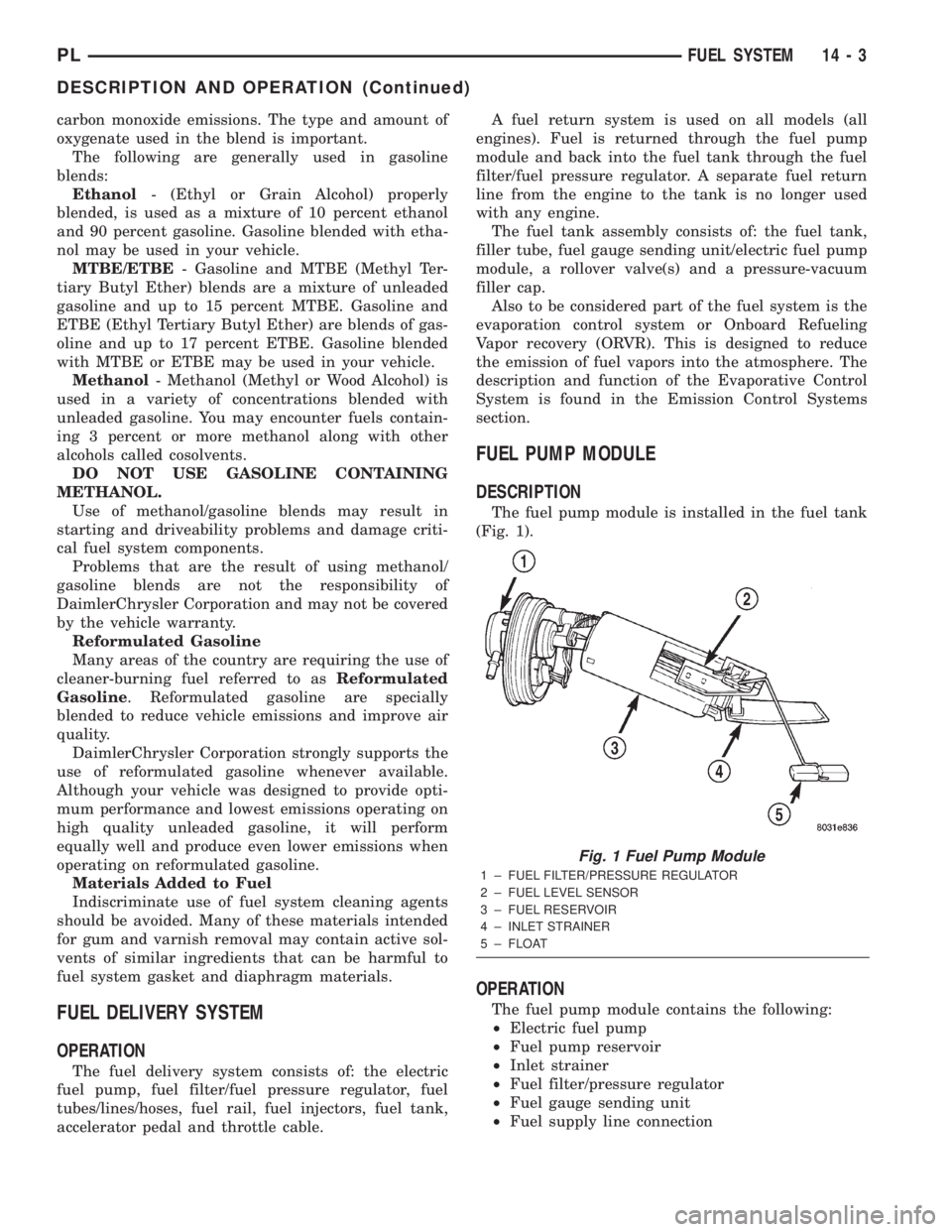
The fuel pump module is installed in the fuel tank
(Fig. 1).
OPERATION
The fuel pump module contains the following:
²Electric fuel pump
²Fuel pump reservoir
²Inlet strainer
²Fuel filter/pressure regulator
²Fuel gauge sending unit
²Fuel supply line connection
Fig. 1 Fuel Pump Module
1 ± FUEL FILTER/PRESSURE REGULATOR
2 ± FUEL LEVEL SENSOR
3 ± FUEL RESERVOIR
4 ± INLET STRAINER
5 ± FLOAT
PLFUEL SYSTEM 14 - 3
DESCRIPTION AND OPERATION (Continued)