2000 DODGE NEON oxygen
[x] Cancel search: oxygenPage 611 of 1285
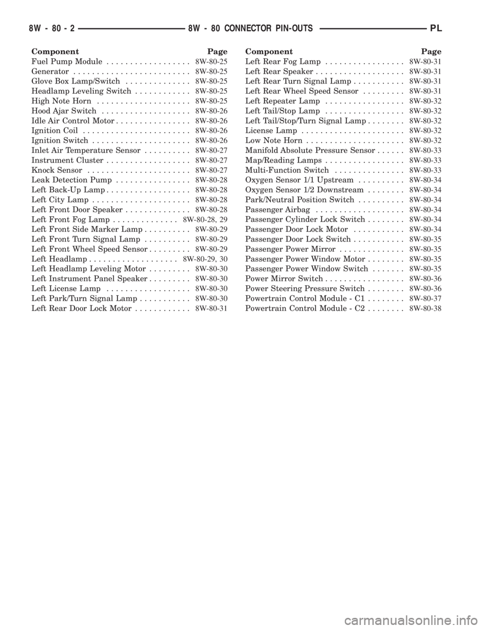
Component Page
Fuel Pump Module..................8W-80-25
Generator.........................8W-80-25
Glove Box Lamp/Switch..............8W-80-25
Headlamp Leveling Switch............8W-80-25
High Note Horn....................8W-80-25
Hood Ajar Switch...................8W-80-26
Idle Air Control Motor................8W-80-26
Ignition Coil.......................8W-80-26
Ignition Switch.....................8W-80-26
Inlet Air Temperature Sensor..........8W-80-27
Instrument Cluster..................8W-80-27
Knock Sensor......................8W-80-27
Leak Detection Pump................8W-80-28
Left Back-Up Lamp..................8W-80-28
Left City Lamp.....................8W-80-28
Left Front Door Speaker..............8W-80-28
Left Front Fog Lamp..............8W-80-28, 29
Left Front Side Marker Lamp..........8W-80-29
Left Front Turn Signal Lamp..........8W-80-29
Left Front Wheel Speed Sensor.........8W-80-29
Left Headlamp...................8W-80-29, 30
Left Headlamp Leveling Motor.........8W-80-30
Left Instrument Panel Speaker.........8W-80-30
Left License Lamp..................8W-80-30
Left Park/Turn Signal Lamp...........8W-80-30
Left Rear Door Lock Motor............8W-80-31Component Page
Left Rear Fog Lamp.................8W-80-31
Left Rear Speaker...................8W-80-31
Left Rear Turn Signal Lamp...........8W-80-31
Left Rear Wheel Speed Sensor.........8W-80-31
Left Repeater Lamp.................8W-80-32
Left Tail/Stop Lamp.................8W-80-32
Left Tail/Stop/Turn Signal Lamp........8W-80-32
License Lamp......................8W-80-32
Low Note Horn.....................8W-80-32
Manifold Absolute Pressure Sensor......8W-80-33
Map/Reading Lamps.................8W-80-33
Multi-Function Switch...............8W-80-33
Oxygen Sensor 1/1 Upstream..........8W-80-34
Oxygen Sensor 1/2 Downstream........8W-80-34
Park/Neutral Position Switch..........8W-80-34
Passenger Airbag...................8W-80-34
Passenger Cylinder Lock Switch........8W-80-34
Passenger Door Lock Motor...........8W-80-34
Passenger Door Lock Switch...........8W-80-35
Passenger Power Mirror..............8W-80-35
Passenger Power Window Motor........8W-80-35
Passenger Power Window Switch.......8W-80-35
Power Mirror Switch.................8W-80-36
Power Steering Pressure Switch........8W-80-36
Powertrain Control Module - C1........8W-80-37
Powertrain Control Module - C2........8W-80-38
8W - 80 - 2 8W - 80 CONNECTOR PIN-OUTSPL
Page 643 of 1285

P36 18PK/VT DOOR UNLOCK DRIVER
P33 18OR/BK DOOR LOCK DRIVER
4 2 GRAY
OXYGEN SENSOR 1/1 SIGNAL 20BK/DG K41 4OXYGEN SENSOR GROUND K127 18BK/OR 3
HEATED OXYGEN SENSOR RELAY CONTROL K79 18OR/RD 2
AUTOMATIC SHUT DOWN RELAY OUTPUT 18DG/OR A142 1
FUNCTION CIRCUIT CAV
CAV CIRCUIT FUNCTION
1
A142 18DG/ORAUTOMATIC SHUT DOWN RELAY OUTPUT
2Z1 18BKGROUND
3K127 18BK/OROXYGEN SENSOR GROUND
4K141 20TN/WT
OXYGEN SENSOR 1/2 SIGNAL
2
41
3
1/2 DOWNSTREAMOXYGEN SENSOR
(2.0L)
FUSED IGNITION SWITCH OUTPUT (RUN) 18WT F20 3PARK/NEUTRAL POSITION SWITCH SENSE 18BR/YL T41 2BACK-UP LAMP FEED 18VT/BK L1 1FUNCTION CIRCUIT CAV
POSITION SWITCHPARK/NEUTRAL
BLACK
3 1
PASSENGER
DOOR LOCK
MOTOR OXYGEN SENSOR
1/1 UPSTREAM
BLACK
34
2 1
4
3
2
-
- 1
FUNCTION CIRCUIT CAV
--
LOCK SWITCH PASSENGER CYLINDER
GROUND Z14 18BK 2PASSENGER DOOR SWITCH MUX P96 18LG 1
FUNCTION CIRCUIT CAV
GRAY 3 1
AIRBAG PASSENGER
YELLOW
1 4
PASSENGER AIRBAG LINE 2 18BK/YL R42 4PASSENGER AIRBAG LINE 1 18DG/YL R44 3
- - 2
- - 1
FUNCTION CIRCUIT CAV
BLACK
(ATX)
8W - 80 - 34 8W-80 CONNECTOR PIN-OUTSPL
008W-10PLI08034
Page 646 of 1285

HEATED OXYGEN SENSOR RELAY CONTROL FUEL INJECTOR NO. 2 DRIVER FUEL INJECTOR NO. 4 DRIVER
37MAP SENSOR SIGNAL 20DG/RD K1 36MODULE - C1CONTROL POWERTRAIN
25
26 K2 20TN/BK
27
28 - -
29 - -
30 K41 20BK/DG OXYGEN SENSOR 1/1 SIGNAL
31
32 K24 20GY/BK CRANKSHAFT POSITION SENSOR SIGNAL
33 K44 20TN/YL CAMSHAFT POSITION SENSOR SIGNAL
34
35 K22 20OR/DB THROTTLE POSITION SENSOR SIGNAL
38 C20 18BR/OR A/C SWITCH SENSE
39 - -
40
BLACK
10 120 1130 2140 31
KNOCK SENSOR SIGNAL 20DB/LG K42 24CLUTCH SWITCH K119 18LG/BK 23- - 22- - 21FUSED IGNITION SWITCH OUTPUT (ST-RUN) 18DB/WT F12
20- - 19K79 18OR/RD 1818TN K12 1718LB/BR K14 16- - 15- - 14FUEL INJECTOR NO. 1 DRIVER 18WT/DB K11 13 12 11GROUND 18BK/TN Z12 10- - 9GENERATOR FIELD DRIVER (+) K20 18DG 8FUEL INJECTOR NO. 3 DRIVER 18YL/WT K13 7AUTOMATIC SHUT DOWN RELAY OUTPUT 18DG/OR A142 6SPEED CONTROL POWER SUPPLY 20YL/RD V32 5 4IGNITION COIL NO. 2 DRIVER 18DB/TN K17 3 2- - 1FUNCTION CIRCUIT CAV
ENGINE COOLANT TEMPERATURE SENSOR SIGNAL --
--
K19 18BK/GY IGNITION COIL NO. 1 DRIVER
ENGINE OIL PRESSURE SWITCH SENSE G6 20GY
K127 18BK/OR
OXYGEN SENSOR GROUND
20TN K90 ENGINE STARTER MOTOR RELAY CONTROL
--
--
SPEED CONTROL- - --
PL8W-80 CONNECTOR PIN-OUTS 8W - 80 - 37
PLI08037008W-10
Page 647 of 1285

POWERTRAIN
CONTROL
MODULE - C2
61 K6 18VT/WT 5V SUPPLY
62 K29 20WT/PK BRAKE LAMP SWITCH SENSE
63 - -
64 C28 18DB/OR A/C COMPRESSOR CLUTCH RELAY CONTROL
65 D21 20PK SCI TRANSMIT
66 G7 20WT/OR VEHICLE SPEED SENSOR SIGNAL
67 K51 18DB/YL AUTOMATIC SHUT DOWN RELAY CONTROL
68 K52 20PK/BK PROPORTIONAL EVAP/PURGE SOLENOID CONTROL
69 - -
70
71
72 K107 18YL LEAK DETECTION PUMP SWITCH SENSE
73
74 K31 18BR FUEL PUMP RELAY CONTROL
75 D20 20LG SCI RECIEVE
76 CLUTCH INTERLOCK SWITCH SENSE
77 K106 18WT/DG LEAK DETECTION PUMP SOLENOID CONTROL
78
79K54 18OR/BK TORQUE CONVERTOR CLUTCH SOLENOID CONTROL
80 V35 20LG/RD SPEED CONTROL VENT SOLENOID CONTROL
BLACK
71 8061 7051 6041 50
- - 60 59
20VT K59 58
IDLE AIR CONTROL NO. 1 DRIVER 20GY/RD K39 57
SPEED CONTROL VACUUM SOLENOID CONTROL 20TN/RD V36 56
55
- - 54
- - 53
INLET AIR TEMPERATURE SENSOR SIGNAL 20VT/LG G31 52
OXYGEN SENSOR 1/2 SIGNAL 20TN/WT K141 51
GROUND 20BK/TN Z12 50
20YL/BK K60 49
IDLE AIR CONTROL NO. 3 DRIVER 20BR/WT K40 48
GROUND 18BK/WT Z11 47
FUSED B(+) 18RD/WT A14 46
POWER STEERING PRESSURE SWITCH SENSE 20WT K10 45
8V SUPPLY 20OR K7 44
SENSOR GROUND 20BK/LB K4 43
- - 42
SPEED CONTROL SWITCH SIGNAL 20RD/LG V37 41
FUNCTION CIRCUIT CAV
IDLE AIR CONTROL NO. 2 DRIVER
IDLE AIR CONTROL NO. 4 DRIVER C27 18DB/PK RADIATOR FAN RELAY CONTROL
D25 20VT/YL
PCI BUS
K108 20DB EVAPORATIVE EMISSION SOLENOID SENSE
G9 18GY/BK RED BRAKE WARNING INDICATOR DRIVER
--
-- 76 T41 18BR/YL PARK/NEUTRAL POSITION SWITCH SENSE
20YL/RD T141
SPEED CONTROLEXCEPT BUILT-UP-EXPORT
MTX
ATX
8W - 80 - 38 8W-80 CONNECTOR PIN-OUTSPL
J008W-10PLI08038
Page 661 of 1285
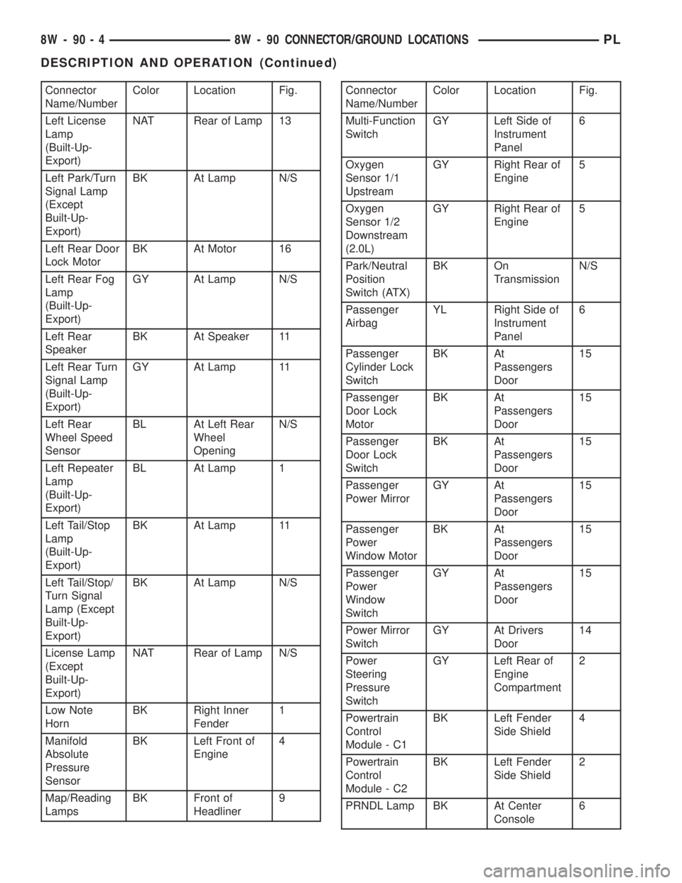
Connector
Name/NumberColor Location Fig.
Left License
Lamp
(Built-Up-
Export)NAT Rear of Lamp 13
Left Park/Turn
Signal Lamp
(Except
Built-Up-
Export)BK At Lamp N/S
Left Rear Door
Lock MotorBK At Motor 16
Left Rear Fog
Lamp
(Built-Up-
Export)GY At Lamp N/S
Left Rear
SpeakerBK At Speaker 11
Left Rear Turn
Signal Lamp
(Built-Up-
Export)GY At Lamp 11
Left Rear
Wheel Speed
SensorBL At Left Rear
Wheel
OpeningN/S
Left Repeater
Lamp
(Built-Up-
Export)BL At Lamp 1
Left Tail/Stop
Lamp
(Built-Up-
Export)BK At Lamp 11
Left Tail/Stop/
Turn Signal
Lamp (Except
Built-Up-
Export)BK At Lamp N/S
License Lamp
(Except
Built-Up-
Export)NAT Rear of Lamp N/S
Low Note
HornBK Right Inner
Fender1
Manifold
Absolute
Pressure
SensorBK Left Front of
Engine4
Map/Reading
LampsBK Front of
Headliner9Connector
Name/NumberColor Location Fig.
Multi-Function
SwitchGY Left Side of
Instrument
Panel6
Oxygen
Sensor 1/1
UpstreamGY Right Rear of
Engine5
Oxygen
Sensor 1/2
Downstream
(2.0L)GY Right Rear of
Engine5
Park/Neutral
Position
Switch (ATX)BK On
TransmissionN/S
Passenger
AirbagYL Right Side of
Instrument
Panel6
Passenger
Cylinder Lock
SwitchBK At
Passengers
Door15
Passenger
Door Lock
MotorBK At
Passengers
Door15
Passenger
Door Lock
SwitchBK At
Passengers
Door15
Passenger
Power MirrorGY At
Passengers
Door15
Passenger
Power
Window MotorBK At
Passengers
Door15
Passenger
Power
Window
SwitchGY At
Passengers
Door15
Power Mirror
SwitchGY At Drivers
Door14
Power
Steering
Pressure
SwitchGY Left Rear of
Engine
Compartment2
Powertrain
Control
Module - C1BK Left Fender
Side Shield4
Powertrain
Control
Module - C2BK Left Fender
Side Shield2
PRNDL Lamp BK At Center
Console6
8W - 90 - 4 8W - 90 CONNECTOR/GROUND LOCATIONSPL
DESCRIPTION AND OPERATION (Continued)
Page 680 of 1285
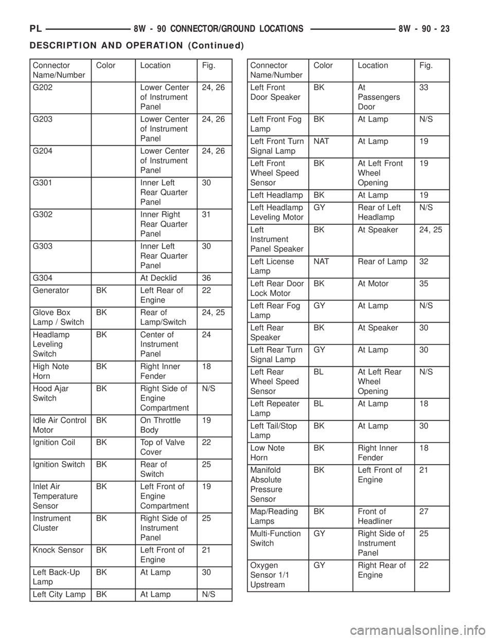
Connector
Name/NumberColor Location Fig.
G202 Lower Center
of Instrument
Panel24, 26
G203 Lower Center
of Instrument
Panel24, 26
G204 Lower Center
of Instrument
Panel24, 26
G301 Inner Left
Rear Quarter
Panel30
G302 Inner Right
Rear Quarter
Panel31
G303 Inner Left
Rear Quarter
Panel30
G304 At Decklid 36
Generator BK Left Rear of
Engine22
Glove Box
Lamp / SwitchBK Rear of
Lamp/Switch24, 25
Headlamp
Leveling
SwitchBK Center of
Instrument
Panel24
High Note
HornBK Right Inner
Fender18
Hood Ajar
SwitchBK Right Side of
Engine
CompartmentN/S
Idle Air Control
MotorBK On Throttle
Body19
Ignition Coil BK Top of Valve
Cover22
Ignition Switch BK Rear of
Switch25
Inlet Air
Temperature
SensorBK Left Front of
Engine
Compartment19
Instrument
ClusterBK Right Side of
Instrument
Panel25
Knock Sensor BK Left Front of
Engine21
Left Back-Up
LampBK At Lamp 30
Left City Lamp BK At Lamp N/SConnector
Name/NumberColor Location Fig.
Left Front
Door SpeakerBK At
Passengers
Door33
Left Front Fog
LampBK At Lamp N/S
Left Front Turn
Signal LampNAT At Lamp 19
Left Front
Wheel Speed
SensorBK At Left Front
Wheel
Opening19
Left Headlamp BK At Lamp 19
Left Headlamp
Leveling MotorGY Rear of Left
HeadlampN/S
Left
Instrument
Panel SpeakerBK At Speaker 24, 25
Left License
LampNAT Rear of Lamp 32
Left Rear Door
Lock MotorBK At Motor 35
Left Rear Fog
LampGY At Lamp N/S
Left Rear
SpeakerBK At Speaker 30
Left Rear Turn
Signal LampGY At Lamp 30
Left Rear
Wheel Speed
SensorBL At Left Rear
Wheel
OpeningN/S
Left Repeater
LampBL At Lamp 18
Left Tail/Stop
LampBK At Lamp 30
Low Note
HornBK Right Inner
Fender18
Manifold
Absolute
Pressure
SensorBK Left Front of
Engine21
Map/Reading
LampsBK Front of
Headliner27
Multi-Function
SwitchGY Right Side of
Instrument
Panel25
Oxygen
Sensor 1/1
UpstreamGY Right Rear of
Engine22
PL8W - 90 CONNECTOR/GROUND LOCATIONS 8W - 90 - 23
DESCRIPTION AND OPERATION (Continued)
Page 681 of 1285
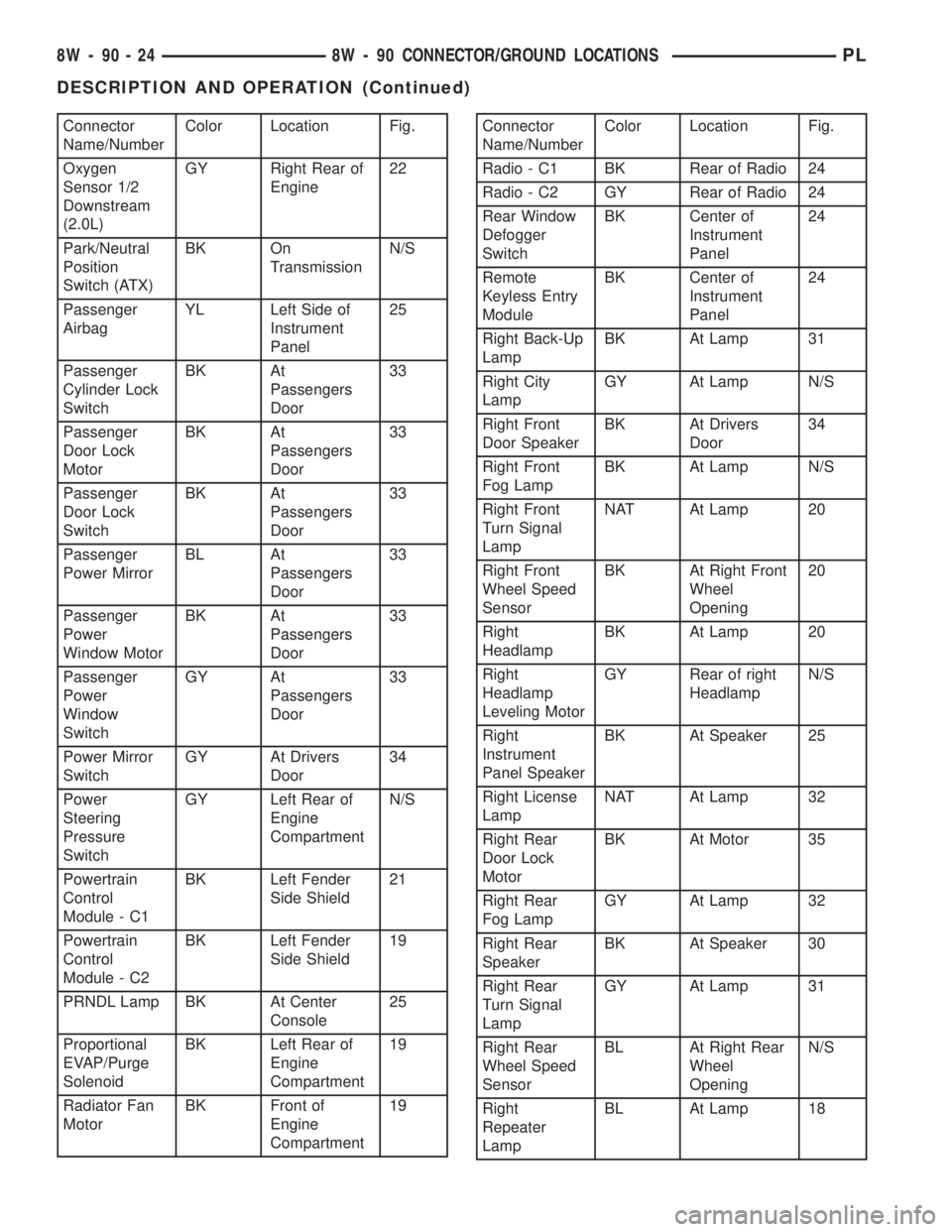
Connector
Name/NumberColor Location Fig.
Oxygen
Sensor 1/2
Downstream
(2.0L)GY Right Rear of
Engine22
Park/Neutral
Position
Switch (ATX)BK On
TransmissionN/S
Passenger
AirbagYL Left Side of
Instrument
Panel25
Passenger
Cylinder Lock
SwitchBK At
Passengers
Door33
Passenger
Door Lock
MotorBK At
Passengers
Door33
Passenger
Door Lock
SwitchBK At
Passengers
Door33
Passenger
Power MirrorBL At
Passengers
Door33
Passenger
Power
Window MotorBK At
Passengers
Door33
Passenger
Power
Window
SwitchGY At
Passengers
Door33
Power Mirror
SwitchGY At Drivers
Door34
Power
Steering
Pressure
SwitchGY Left Rear of
Engine
CompartmentN/S
Powertrain
Control
Module - C1BK Left Fender
Side Shield21
Powertrain
Control
Module - C2BK Left Fender
Side Shield19
PRNDL Lamp BK At Center
Console25
Proportional
EVAP/Purge
SolenoidBK Left Rear of
Engine
Compartment19
Radiator Fan
MotorBK Front of
Engine
Compartment19Connector
Name/NumberColor Location Fig.
Radio - C1 BK Rear of Radio 24
Radio - C2 GY Rear of Radio 24
Rear Window
Defogger
SwitchBK Center of
Instrument
Panel24
Remote
Keyless Entry
ModuleBK Center of
Instrument
Panel24
Right Back-Up
LampBK At Lamp 31
Right City
LampGY At Lamp N/S
Right Front
Door SpeakerBK At Drivers
Door34
Right Front
Fog LampBK At Lamp N/S
Right Front
Turn Signal
LampNAT At Lamp 20
Right Front
Wheel Speed
SensorBK At Right Front
Wheel
Opening20
Right
HeadlampBK At Lamp 20
Right
Headlamp
Leveling MotorGY Rear of right
HeadlampN/S
Right
Instrument
Panel SpeakerBK At Speaker 25
Right License
LampNAT At Lamp 32
Right Rear
Door Lock
MotorBK At Motor 35
Right Rear
Fog LampGY At Lamp 32
Right Rear
SpeakerBK At Speaker 30
Right Rear
Turn Signal
LampGY At Lamp 31
Right Rear
Wheel Speed
SensorBL At Right Rear
Wheel
OpeningN/S
Right
Repeater
LampBL At Lamp 18
8W - 90 - 24 8W - 90 CONNECTOR/GROUND LOCATIONSPL
DESCRIPTION AND OPERATION (Continued)
Page 749 of 1285
(4) Discharge air conditioning system, if equipped.
Refer to Group 24, Heating and Air Conditioning for
procedure.
(5) Disconnect the following: air intake duct at
intake manifold, throttle cables, electrical connectors
from throttle body and air cleaner housing.
(6) Remove air cleaner housing assembly.
(7) Remove upper radiator hose and fan module.
Refer to Group 7, Cooling System for procedure.
(8) Remove lower radiator hose.
(9) Disconnect automatic transmission cooler lines
and plug, if equipped.
(10) Disconnect shift linkage, electrical connectors,
and clutch cable, if equipped with manual transaxle.
(11) Disconnect engine wiring harness.
(12) Disconnect positive cable from Power Distri-
bution Center (PDC) and ground wire from vehicle
body.
(13) Disconnect ground wire from the vehicle body-
to-engine at the right side strut tower.
(14) Disconnect heater hoses.
(15) Disconnect vacuum hose from brake booster.
(16) Disconnect coolant reserve/recovery hose.
(17) Remove accessory drive belts. Refer to Group
7, Cooling System for procedure.
(18) Remove power steering pump and reservoir
and set them aside.
(19) Hoist vehicle and remove right inner splash
shield.
(20) Drain engine oil.
(21) Remove front wheels.
(22) Remove axle shafts. Refer to Group 3, Differ-
ential and Driveline for procedure.
(23) Disconnect exhaust system from manifold.
(24) Disconnect the downstream oxygen sensor
connector.
(25) Remove lower engine torque strut.
(26) Remove structural collar. Refer to procedure
in this section.
(27) Lower vehicle and remove A/C compressor.
(28) Raise vehicle enough to allow engine dolly
and cradle, Special Tools 6135 and 6710 to be
installed under vehicle.
(29) Loosen engine support posts to allow move-
ment for positioning onto engine locating holes and
flange on the engine bedplate. Lower vehicle and
position cradle until the engine is resting on support
posts (Fig. 26). Tighten mounts to cradle frame. This
will keep support posts from moving when removing
or installing engine and transmission.
(30) Install safety straps around the engine to cra-
dle (Fig. 26). Tighten straps and lock them into posi-
tion.
WARNING: Safety straps MUST be used.(31) Raise vehicle enough to see if straps are tight
enough to hold cradle assembly to engine.
(32) Lower vehicle so weight of the engine and
transmission ONLY is on the cradle assembly.
(33) Remove the upper engine torque strut.
(34) Remove right and left engine and transaxle
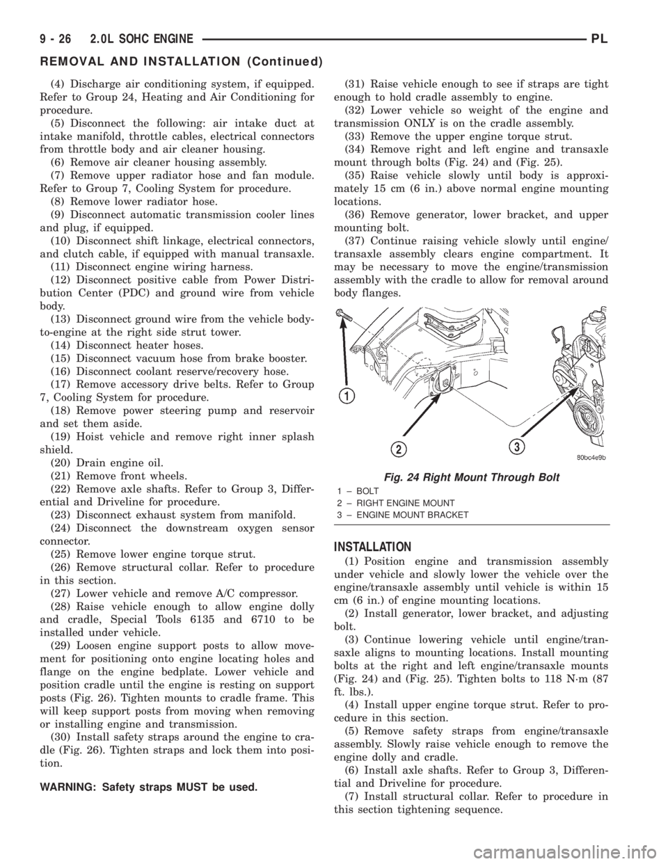
mount through bolts (Fig. 24) and (Fig. 25).
(35) Raise vehicle slowly until body is approxi-
mately 15 cm (6 in.) above normal engine mounting
locations.
(36) Remove generator, lower bracket, and upper
mounting bolt.
(37) Continue raising vehicle slowly until engine/
transaxle assembly clears engine compartment. It
may be necessary to move the engine/transmission
assembly with the cradle to allow for removal around
body flanges.
INSTALLATION
(1) Position engine and transmission assembly
under vehicle and slowly lower the vehicle over the
engine/transaxle assembly until vehicle is within 15
cm (6 in.) of engine mounting locations.
(2) Install generator, lower bracket, and adjusting
bolt.
(3) Continue lowering vehicle until engine/tran-
saxle aligns to mounting locations. Install mounting
bolts at the right and left engine/transaxle mounts
(Fig. 24) and (Fig. 25). Tighten bolts to 118 N´m (87
ft. lbs.).
(4) Install upper engine torque strut. Refer to pro-
cedure in this section.
(5) Remove safety straps from engine/transaxle
assembly. Slowly raise vehicle enough to remove the
engine dolly and cradle.
(6) Install axle shafts. Refer to Group 3, Differen-
tial and Driveline for procedure.
(7) Install structural collar. Refer to procedure in
this section tightening sequence.
Fig. 24 Right Mount Through Bolt
1 ± BOLT
2 ± RIGHT ENGINE MOUNT
3 ± ENGINE MOUNT BRACKET
9 - 26 2.0L SOHC ENGINEPL
REMOVAL AND INSTALLATION (Continued)