2000 DODGE NEON oxygen
[x] Cancel search: oxygenPage 854 of 1285
grammed (fixed) values and inputs from other sen-
sors.
DOWNSTREAM OXYGEN SENSOR 1/2
The Downstream O2 Sensor has two functions.
One function is measuring catalyst efficiency. This is
an OBD II requirement. The oxygen content of theexhaust gasses has significantly less fluctuation than
at the inlet if the converter is working properly. The
PCM compares upstream and Downstream O2 Sen-
sor switch rates under specific operating conditions
to determine if the catalyst is functioning properly.
The other function is a downstream fuel control
which was introduced in 1996. The upstream O2 goal
varies within the window of operation of the O2 Sen-
sor. In the past the goal was a preprogrammed fixed
value based upon where it believed the catalyst oper-
ated most efficiently.
While the Upstream O2 Sensor input is used to
maintain the 14.7:1 air/fuel ratio, variations in
engines, exhaust systems and catalytic converters
may cause this ratio to not be the most ideal for a
particular catalyst and engine. To help maintain the
catalyst operating at maximum efficiency, the PCM
will fine tune the air/fuel ratio entering the catalyst
based upon the oxygen content leaving the catalyst.
This is accomplished by modifying the Upstream O2
Sensor voltage goal.
If the exhaust leaving the catalyst has too much
oxygen (lean ) the PCM increases the upstream O2
goal which increases fuel in the mixture causing less
oxygen to be left over. Conversely, if the oxygen con-
tent leaving the catalyst has is too little oxygen (rich)
the PCM decreases the upstream O2 goal down
which removes fuel from the mixture causing more
oxygen to be left over. This function only occurs dur-
ing downstream closed loop mode operation.
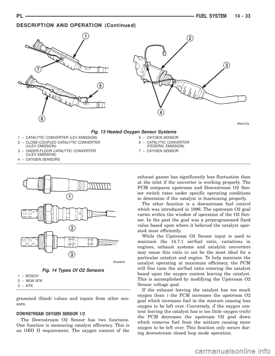
Fig. 13 Heated Oxygen Sensor Systems
1 ± CATALYTIC CONVERTER (LEV EMISSION)
2 ± CLOSE-COUPLED CATALYTIC CONVERTER
(ULEV EMISSION)
3 ± UNDER-FLOOR CATALYTIC CONVERTER
(ULEV EMISSION)
4 ± OXYGEN SENSORS5 ± OXYGEN SENSOR
6 ± CATALYTIC CONVERTER
(FEDERAL EMISSION)
7 ± OXYGEN SENSOR
Fig. 14 Types Of O2 Sensors
1 ± BOSCH
2 ± NEW NTK
3 ± NTK
PLFUEL SYSTEM 14 - 33
DESCRIPTION AND OPERATION (Continued)
Page 859 of 1285
Like all Hall-effect sensors, the electronics of the
sensor needs a power source. This power source is
provided by the PCM. It is the same 8 volt power
supply that is used by the CKP and CMP sensors.
The vehicle speed sensor generates 8 pulses per
sensor revolution. This signal, in conjunction with a
closed throttle signal from the throttle position sen-
sor, indicates a closed throttle deceleration to the
PCM. Under deceleration conditions, the PCM
adjusts the Idle Air Control (IAC) motor to maintain
a desired MAP value.
When the vehicle is stopped at idle, a closed throt-
tle signal is received by the PCM (but a speed sensor
signal is not received). Under idle conditions, the
PCM adjusts the IAC motor to maintain a desired
engine speed.
AIR CONDITIONING CLUTCH RELAYÐPCM
OUTPUT
DESCRIPTION
The air conditioning clutch relay is located in the
PDC. The inside top of the PDC cover has a label
showing relay and fuse location.
OPERATION
The PCM controls the air conditioning clutch relay
ground circuit. The A/C clutch relay coil side contains
a 10 amp fuse between the buss bar in the Power
Distribution Center (PDC) and the relay. The power
side of this relay is fused with a 40 amp fuse. When
the PCM receives an air conditioning input, it
grounds the A/C compressor clutch relay and the
radiator fan relay.
When the PCM senses low idle speeds or wide open
throttle through the throttle position sensor, it
removes the ground for the A/C compressor clutch
relay. When the relay de-energizes, the contacts open
preventing air conditioning clutch engagement. Also,
if the PCM senses a part throttle launch condition, it
disables the A/C compressor clutch for several sec-
onds.
AUTOMATIC SHUTDOWN RELAYÐPCM
OUTPUT
DESCRIPTION
The ASD relay is located in the PDC. The inside
top of the PDC cover has a label showing relay and
fuse location.
OPERATION
The automatic shutdown (ASD) relay supplies bat-
tery voltage to the fuel injectors, electronic ignition
coil and the heating elements in the oxygen sensors
generator field and PCM sense circuit.A buss bar in the power distribution center (PDC)
supplies voltage to the solenoid side and contact side
of the relay. The ASD relay power circuit contains a
fuse between the buss bar in the PDC and the relay.
The fuse also protects the power circuit for the fuel
pump relay and pump. The fuse is located in the
PDC. Refer to the Wiring Diagrams for circuit infor-
mation.
The PCM controls the relay by switching the
ground path for the solenoid side of the relay on and
off. The PCM turns the ground path off when the
ignition switch is in the Off position unless the 02
Heater Monitor test is being run. When the ignition
switch is in the On or Crank position, the PCM mon-
itors the crankshaft position sensor and camshaft
position sensor signals to determine engine speed
and ignition timing (coil dwell). If the PCM does not
receive the crankshaft position sensor and camshaft
position sensor signals when the ignition switch is in
the Run position, it will de-energize the ASD relay.
CHARGING SYSTEM INDICATOR LAMPÐPCM
OUTPUT
OPERATION
The PCM turns the instrument panel Charging
System Lamp on. Refer to the Charging system sec-
tion information.
FUEL PUMP RELAYÐPCM OUTPUT
DESCRIPTION
The fuel pump relay is located in the PDC. The
inside top of the PDC cover has a label showing relay
and fuse location.
OPERATION
The fuel pump relay supplies battery voltage to the
fuel pump. A buss bar in the Power Distribution Cen-
ter (PDC) supplies voltage to the solenoid side and
contact side of the relay. The fuel pump relay power
circuit contains a fuse between the buss bar in the
PDC and the relay. The fuse also protects the power
circuit for the Automatic Shutdown (ASD) relay. The
fuse is located in the PDC. Refer to the Wiring Dia-
grams for circuit information.
The PCM controls the fuel pump relay by switch-
ing the ground path for the solenoid side of the relay
on and off. The PCM turns the ground path off when
the ignition switch is in the Off position. When the
ignition switch is in the On position, the PCM ener-
gizes the fuel pump. If the crankshaft position sensor
does not detect engine rotation, the PCM de-ener-
gizes the relay after approximately one second.
14 - 38 FUEL SYSTEMPL
DESCRIPTION AND OPERATION (Continued)
Page 866 of 1285
(5) Remove the nut from the upper bracket mount.
(6) Raise vehicle and support on hoist.
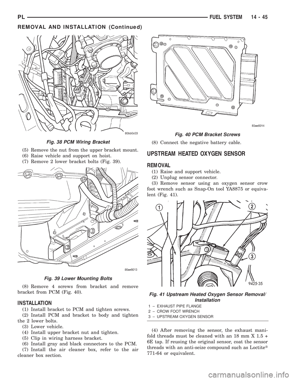
(7) Remove 2 lower bracket bolts (Fig. 39).
(8) Remove 4 screws from bracket and remove
bracket from PCM (Fig. 40).
INSTALLATION
(1) Install bracket to PCM and tighten screws.
(2) Install PCM and bracket to body and tighten
the 2 lower bolts.
(3) Lower vehicle.
(4) Install upper bracket nut and tighten.
(5) Clip in wiring harness bracket.
(6) Install gray and black connectors to the PCM.
(7) Install the air cleaner box, refer to the air
cleaner box section.(8) Connect the negative battery cable.
UPSTREAM HEATED OXYGEN SENSOR
REMOVAL
(1) Raise and support vehicle.
(2) Unplug sensor connector.
(3) Remove sensor using an oxygen sensor crow
foot wrench such as Snap-On tool YA8875 or equiva-
lent (Fig. 41).
(4) After removing the sensor, the exhaust mani-
fold threads must be cleaned with an 18 mm X 1.5 +
6E tap. If reusing the original sensor, coat the sensor
threads with an anti-seize compound such as Loctitet
771-64 or equivalent.
Fig. 38 PCM Wiring Bracket
Fig. 39 Lower Mounting Bolts
Fig. 40 PCM Bracket Screws
Fig. 41 Upstream Heated Oxygen Sensor Removal/
Installation
1 ± EXHAUST PIPE FLANGE
2 ± CROW FOOT WRENCH
3 ± UPSTREAM OXYGEN SENSOR
PLFUEL SYSTEM 14 - 45
REMOVAL AND INSTALLATION (Continued)
Page 867 of 1285
INSTALLATION
New sensors have compound on the threads and do
not require an additional coating.
(1) Install sensor using an oxygen sensor crow foot
wrench such as Snap-On tool YA8875 or equivalent
(Fig. 41). Tighten the sensor to 28 N´m (20 ft. lbs.)
torque.
(2) Plug sensor connector.
(3) Lower vehicle.
DOWNSTREAM HEATED OXYGEN SENSOR 1/2
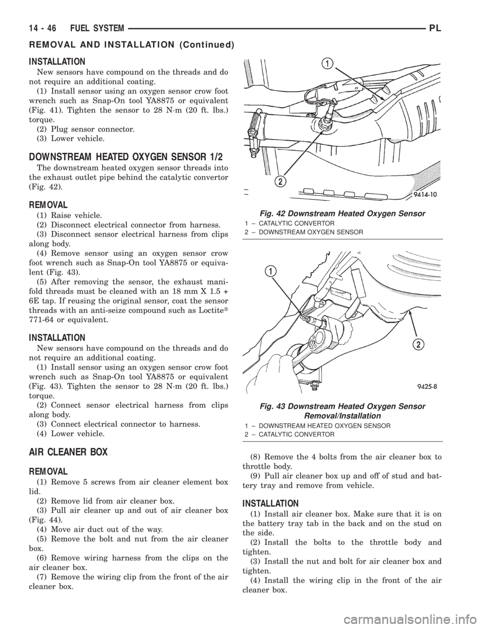
The downstream heated oxygen sensor threads into
the exhaust outlet pipe behind the catalytic convertor
(Fig. 42).
REMOVAL
(1) Raise vehicle.
(2) Disconnect electrical connector from harness.
(3) Disconnect sensor electrical harness from clips
along body.
(4) Remove sensor using an oxygen sensor crow
foot wrench such as Snap-On tool YA8875 or equiva-
lent (Fig. 43).
(5) After removing the sensor, the exhaust mani-
fold threads must be cleaned with an 18 mm X 1.5 +
6E tap. If reusing the original sensor, coat the sensor
threads with an anti-seize compound such as Loctitet
771-64 or equivalent.
INSTALLATION
New sensors have compound on the threads and do
not require an additional coating.
(1) Install sensor using an oxygen sensor crow foot
wrench such as Snap-On tool YA8875 or equivalent
(Fig. 43). Tighten the sensor to 28 N´m (20 ft. lbs.)
torque.
(2) Connect sensor electrical harness from clips
along body.
(3) Connect electrical connector to harness.
(4) Lower vehicle.
AIR CLEANER BOX
REMOVAL
(1) Remove 5 screws from air cleaner element box
lid.
(2) Remove lid from air cleaner box.
(3) Pull air cleaner up and out of air cleaner box
(Fig. 44).
(4) Move air duct out of the way.
(5) Remove the bolt and nut from the air cleaner
box.
(6) Remove wiring harness from the clips on the
air cleaner box.
(7) Remove the wiring clip from the front of the air
cleaner box.(8) Remove the 4 bolts from the air cleaner box to
throttle body.
(9) Pull air cleaner box up and off of stud and bat-
tery tray and remove from vehicle.
INSTALLATION
(1) Install air cleaner box. Make sure that it is on
the battery tray tab in the back and on the stud on
the side.
(2) Install the bolts to the throttle body and
tighten.
(3) Install the nut and bolt for air cleaner box and
tighten.
(4) Install the wiring clip in the front of the air
cleaner box.
Fig. 42 Downstream Heated Oxygen Sensor
1 ± CATALYTIC CONVERTOR
2 ± DOWNSTREAM OXYGEN SENSOR
Fig. 43 Downstream Heated Oxygen Sensor
Removal/Installation
1 ± DOWNSTREAM HEATED OXYGEN SENSOR
2 ± CATALYTIC CONVERTOR
14 - 46 FUEL SYSTEMPL
REMOVAL AND INSTALLATION (Continued)
Page 870 of 1285
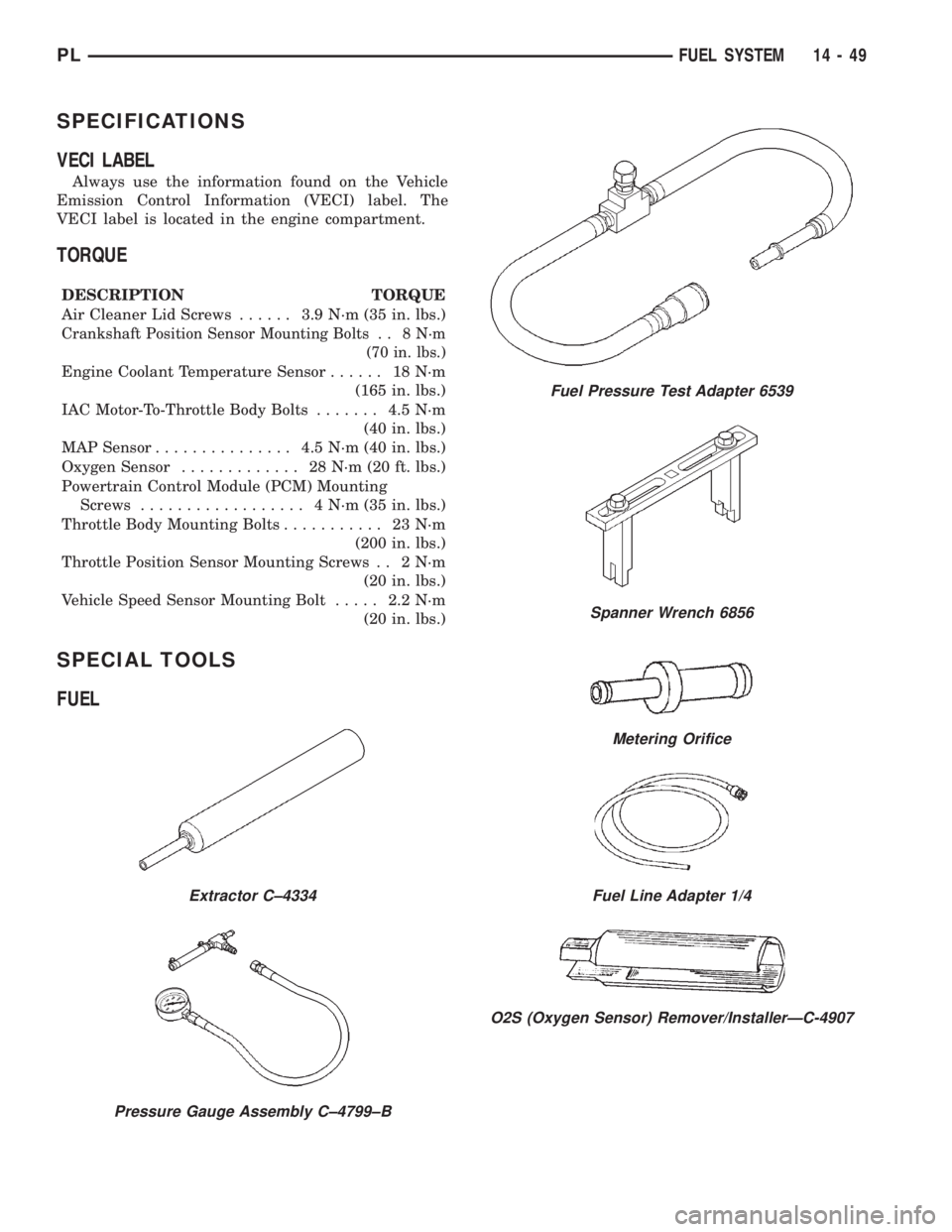
SPECIFICATIONS
VECI LABEL
Always use the information found on the Vehicle
Emission Control Information (VECI) label. The
VECI label is located in the engine compartment.
TORQUE
DESCRIPTION TORQUE
Air Cleaner Lid Screws...... 3.9N´m(35in.lbs.)
Crankshaft Position Sensor Mounting Bolts . . 8 N´m
(70 in. lbs.)
Engine Coolant Temperature Sensor...... 18N´m
(165 in. lbs.)
IAC Motor-To-Throttle Body Bolts....... 4.5N´m
(40 in. lbs.)
MAP Sensor............... 4.5N´m(40in.lbs.)
Oxygen Sensor............. 28N´m(20ft.lbs.)
Powertrain Control Module (PCM) Mounting
Screws.................. 4N´m(35in.lbs.)
Throttle Body Mounting Bolts........... 23N´m
(200 in. lbs.)
Throttle Position Sensor Mounting Screws . . 2 N´m
(20 in. lbs.)
Vehicle Speed Sensor Mounting Bolt..... 2.2N´m
(20 in. lbs.)
SPECIAL TOOLS
FUEL
Extractor C±4334
Pressure Gauge Assembly C±4799±B
Fuel Pressure Test Adapter 6539
Spanner Wrench 6856
Metering Orifice
Fuel Line Adapter 1/4
O2S (Oxygen Sensor) Remover/InstallerÐC-4907
PLFUEL SYSTEM 14 - 49
Page 1088 of 1285
EMISSION CONTROL SYSTEMS
TABLE OF CONTENTS
page page
ON-BOARD DIAGNOSTICS................... 1 EVAPORATIVE EMISSION CONTROLS......... 25
ON-BOARD DIAGNOSTICS
TABLE OF CONTENTS
page page
DESCRIPTION AND OPERATION
SYSTEM DESCRIPTION....................1
TASK MANAGER..........................2
MALFUNCTION INDICATOR LAMP (MIL)........5
DRB III STATE DISPLAY TEST MODE..........5
DRB III CIRCUIT ACTUATION TEST MODE......5
DIAGNOSTIC TROUBLE CODES..............5
DIAGNOSTIC TROUBLE CODE
DESCRIPTIONS.........................6MONITORED SYSTEMS....................15
TRIP DEFINITION........................19
MONITORED COMPONENT.................19
NON-MONITORED CIRCUITS...............23
HIGH AND LOW LIMITS....................24
LOAD VALUE............................24
DESCRIPTION AND OPERATION
SYSTEM DESCRIPTION
DESCRIPTION
OBD II requires that vehicles falling under OBD II
guidelines utilize the following system monitors:
²Comprehensive Component Monitor (inputs/out-
puts for powertrain management that affect emis-
sions, but do not have a specific major monitor)
²Fuel Control Monitor (fuel compensation
required to maintain stoichiometric ratio rich/lean)
²Misfire Monitor (change in crankshaft speed)
²Oxygen Sensor Heater Monitor (response and
performance of oxygen sensors)
²Catalyst Monitor (Performance and efficiency of
catalyst)
²Evaporative Emissions Monitor (performance of
and leaks from EVAP system)
²Exhaust Gas Recirculation Monitor (flow perfor-
mance of EGR system)
The software was rewritten to enable the PCM to
carry out the responsibilities to meet these required
guidelines. The PCM now contains a Task Manager.
OPERATION
The Powertrain Control Module (PCM) monitors
many different circuits in the fuel injection, ignition,
emission and engine systems. If the PCM senses a
problem with a monitored circuit often enough to
indicate an actual problem, it stores a Diagnostic
Trouble Code (DTC) in the PCM's memory. If the
code applies to a non-emissions related component or
system, and the problem is repaired or ceases to
exist, the PCM cancels the code after 40 warmup
cycles. Diagnostic trouble codes that affect vehicle
emissions illuminate the Malfunction Indicator Lamp
(MIL). Refer to Malfunction Indicator Lamp in this
section.
Certain criteria must be met before the PCM
stores a DTC in memory. The criteria may be a spe-
cific range of engine RPM, engine temperature,
and/or input voltage to the PCM.
The PCM might not store a DTC for a monitored
circuit even though a malfunction has occurred. This
may happen because one of the DTC criteria for the
circuit has not been met.For example, assume the
diagnostic trouble code criteria requires the PCM to
monitor the circuit only when the engine operates
between 750 and 2000 RPM. Suppose the sensor's
output circuit shorts to ground when engine operates
above 2400 RPM (resulting in 0 volt input to the
PLEMISSION CONTROL SYSTEMS 25 - 1
Page 1089 of 1285
PCM). Because the condition happens at an engine
speed above the maximum threshold (2000 rpm), the
PCM will not store a DTC.
There are several operating conditions for which
the PCM monitors and sets DTC's. Refer to Moni-
tored Systems, Components, and Non-Monitored Cir-
cuits in this section.
NOTE: Various diagnostic procedures may actually
cause a diagnostic monitor to set a DTC. For
instance, pulling a spark plug wire to perform a
spark test may set the misfire code. When a repair
is completed and verified, use the DRB III scan tool
to erase all DTC's and extinguish the MIL.
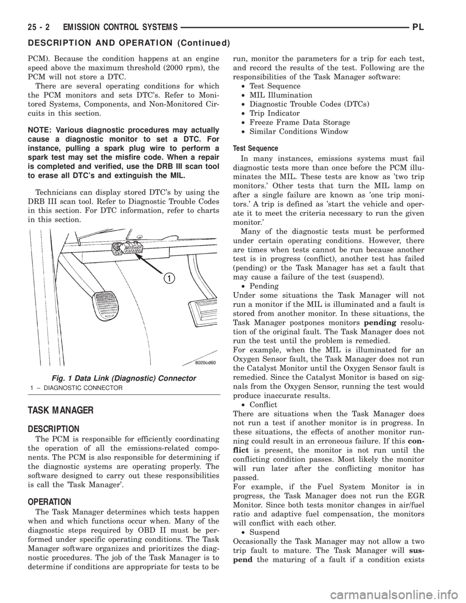
Technicians can display stored DTC's by using the
DRB III scan tool. Refer to Diagnostic Trouble Codes
in this section. For DTC information, refer to charts
in this section.
TASK MANAGER
DESCRIPTION
The PCM is responsible for efficiently coordinating
the operation of all the emissions-related compo-
nents. The PCM is also responsible for determining if
the diagnostic systems are operating properly. The
software designed to carry out these responsibilities
is call the 'Task Manager'.
OPERATION
The Task Manager determines which tests happen
when and which functions occur when. Many of the
diagnostic steps required by OBD II must be per-
formed under specific operating conditions. The Task
Manager software organizes and prioritizes the diag-
nostic procedures. The job of the Task Manager is to
determine if conditions are appropriate for tests to berun, monitor the parameters for a trip for each test,
and record the results of the test. Following are the
responsibilities of the Task Manager software:
²Test Sequence
²MIL Illumination
²Diagnostic Trouble Codes (DTCs)
²Trip Indicator
²Freeze Frame Data Storage
²Similar Conditions Window
Test Sequence
In many instances, emissions systems must fail
diagnostic tests more than once before the PCM illu-
minates the MIL. These tests are know as 'two trip
monitors.' Other tests that turn the MIL lamp on
after a single failure are known as 'one trip moni-
tors.' A trip is defined as 'start the vehicle and oper-
ate it to meet the criteria necessary to run the given
monitor.'
Many of the diagnostic tests must be performed
under certain operating conditions. However, there
are times when tests cannot be run because another
test is in progress (conflict), another test has failed
(pending) or the Task Manager has set a fault that
may cause a failure of the test (suspend).
²Pending
Under some situations the Task Manager will not
run a monitor if the MIL is illuminated and a fault is
stored from another monitor. In these situations, the
Task Manager postpones monitorspendingresolu-
tion of the original fault. The Task Manager does not
run the test until the problem is remedied.
For example, when the MIL is illuminated for an
Oxygen Sensor fault, the Task Manager does not run
the Catalyst Monitor until the Oxygen Sensor fault is
remedied. Since the Catalyst Monitor is based on sig-
nals from the Oxygen Sensor, running the test would
produce inaccurate results.
²Conflict
There are situations when the Task Manager does
not run a test if another monitor is in progress. In
these situations, the effects of another monitor run-
ning could result in an erroneous failure. If thiscon-
flictis present, the monitor is not run until the
conflicting condition passes. Most likely the monitor
will run later after the conflicting monitor has
passed.
For example, if the Fuel System Monitor is in
progress, the Task Manager does not run the EGR
Monitor. Since both tests monitor changes in air/fuel
ratio and adaptive fuel compensation, the monitors
will conflict with each other.
²Suspend
Occasionally the Task Manager may not allow a two
trip fault to mature. The Task Manager willsus-
pendthe maturing of a fault if a condition exists
Fig. 1 Data Link (Diagnostic) Connector
1 ± DIAGNOSTIC CONNECTOR
25 - 2 EMISSION CONTROL SYSTEMSPL
DESCRIPTION AND OPERATION (Continued)
Page 1090 of 1285
that may induce an erroneous failure. This prevents
illuminating the MIL for the wrong fault and allows
more precis diagnosis.
For example, if the PCM is storing a one trip fault
for the Oxygen Sensor and the EGR monitor, the
Task Manager may still run the EGR Monitor but
will suspend the results until the Oxygen Sensor
Monitor either passes or fails. At that point the Task
Manager can determine if the EGR system is actu-
ally failing or if an Oxygen Sensor is failing.
MIL Illumination
The PCM Task Manager carries out the illumina-
tion of the MIL. The Task Manager triggers MIL illu-
mination upon test failure, depending on monitor
failure criteria.
The Task Manager Screen shows both a Requested
MIL state and an Actual MIL state. When the MIL is
illuminated upon completion of a test for a third trip,
the Requested MIL state changes to OFF. However,
the MIL remains illuminated until the next key
cycle. (On some vehicles, the MIL will actually turn
OFF during the third key cycle) During the key cycle
for the third good trip, the Requested MIL state is
OFF, while the Actual MILL state is ON. After the
next key cycle, the MIL is not illuminated and both
MIL states read OFF.
Diagnostic Trouble Codes (DTCs)
With OBD II, different DTC faults have different
priorities according to regulations. As a result, the
priorities determine MIL illumination and DTC era-
sure. DTCs are entered according to individual prior-
ity. DTCs with a higher priority overwrite lower
priority DTCs.
Priorities
²Priority 0 ÐNon-emissions related trouble codes
²Priority 1 Ð One trip failure of a two trip fault
for non-fuel system and non-misfire.
²Priority 2 Ð One trip failure of a two trip fault
for fuel system (rich/lean) or misfire.
²Priority3ÐTwotrip failure for a non-fuel sys-
tem and non-misfire or matured one trip comprehen-
sive component fault.
²Priority4ÐTwotrip failure or matured fault
for fuel system (rich/lean) and misfire or one trip cat-
alyst damaging misfire.
Non-emissions related failures have no priority.
One trip failures of two trip faults have low priority.
Two trip failures or matured faults have higher pri-
ority. One and two trip failures of fuel system and
misfire monitor take precedence over non-fuel system
and non-misfire failures.DTC Self Erasure
With one trip components or systems, the MIL is
illuminated upon test failure and DTCs are stored.
Two trip monitors are components requiring failure
in two consecutive trips for MIL illumination. Upon
failure of the first test, the Task Manager enters a
maturing code. If the component fails the test for a
second time the code matures and a DTC is set.
After three good trips the MIL is extinguished and
the Task Manager automatically switches the trip
counter to a warm-up cycle counter. DTCs are auto-
matically erased following 40 warm-up cycles if the
component does not fail again.
For misfire and fuel system monitors, the compo-
nent must pass the test under a Similar Conditions
Window in order to record a good trip. A Similar Con-
ditions Window is when engine RPM is within6375
RPM and load is within610% of when the fault
occurred.
NOTE: It is important to understand that a compo-
nent does not have to fail under a similar window of
operation to mature. It must pass the test under a
Similar Conditions Window when it failed to record
a Good Trip for DTC erasure for misfire and fuel
system monitors.
DTCs can be erased anytime with a DRB III. Eras-
ing the DTC with the DRB III erases all OBD II
information. The DRB III automatically displays a
warning that erasing the DTC will also erase all
OBD II monitor data. This includes all counter infor-
mation for warm-up cycles, trips and Freeze Frame.
Trip Indicator
TheTripis essential for running monitors and
extinguishing the MIL. In OBD II terms, a trip is a
set of vehicle operating conditions that must be met
for a specific monitor to run. All trips begin with a
key cycle.
Good Trip
The Good Trip counters are as follows:
²Global Good Trip
²Fuel System Good Trip
²Misfire Good Trip
²Alternate Good Trip (appears as a Global Good
Trip on DRB III)
²Comprehensive Components
²Major Monitor
²Warm-Up Cycles
Global Good Trip
To increment a Global Good Trip, the Oxygen sen-
sor and Catalyst efficiency monitors must have run
and passed.
Fuel System Good Trip
To count a good trip (three required) and turn off
the MIL, the following conditions must occur:
PLEMISSION CONTROL SYSTEMS 25 - 3
DESCRIPTION AND OPERATION (Continued)