2000 DODGE NEON ignition
[x] Cancel search: ignitionPage 823 of 1285
REFORMULATED GASOLINE
Many areas of the country require the use of
cleaner burning gasoline referred to as ªreformulat-
edº gasoline. Reformulated gasoline contain oxygen-
ates, and are specifically blended to reduce vehicle
emissions and improve air quality.
DaimlerChrysler Corporation strongly supports the
use of reformulated gasoline. Properly blended refor-
mulated gasoline will provide excellent performance
and durability for the engine and fuel system compo-
nents.
GASOLINE/OXYGENATE BLENDS
Some fuel suppliers blend unleaded gasoline with
oxygenates such as 10% ethanol, MTBE, and ETBE.
Oxygenates are required in some areas of the country
during the winter months to reduce carbon monoxide
emissions. Fuels blended with these oxygenates may
be used in your vehicle.
CAUTION: DO NOT use gasoline containing METH-
ANOL. Gasoline containing methanol may damage
critical fuel system components.
MMT
MMT is a manganese-containing metallic additive
that is blended into some gasoline to increase octane.
Gasoline blended with MMT provide no performance
advantage beyond gasoline of the same octane num-
ber without MMT. Gasoline blended with MMT
reduce spark plug life and reduce emission system
performance in some vehicles. DaimlerChrysler rec-
ommends that gasoline without MMT be used in your
vehicle. The MMT content of gasoline may not be
indicated on the gasoline pump; therefore, you should
ask your gasoline retailer whether or not his/her gas-
oline contains MMT.
It is even more important to look for gasoline with-
out MMT in Canada because MMT can be used at
levels higher than allowed in the United States.
MMT is prohibited in Federal and California refor-
mulated gasoline.
SULFUR IN GASOLINE
If you live in the northeast United States, your
vehicle may have been designed to meet California
low emission standards with clean-burning, low-sul-
fur, California gasoline. Gasoline sold outside of Cal-
ifornia is permitted to have higher sulfur levels
which may affect the performance of the vehicle's cat-
alytic converter. This may cause the Check Engine or
Service Engine Soon light to illuminate.
Illumination of either light while operating on high
sulfur gasoline does not necessarily mean your emis-
sion control system is malfunctioning. DaimlerChrysler
recommends that you try a different brand of unleadedgasoline having lower sulfur to determine if the prob-
lem is fuel related prior to returning your vehicle to an
authorized dealer for service.
CAUTION: If the Check Engine or Service Engine
Soon light is flashing, immediate service is
required; see on-board diagnostics system section.
MATERIALS ADDED TO FUEL
All gasoline sold in the United States and Canada
are required to contain effective detergent additives.
Use of additional detergents or other additives is not
needed under normal conditions.
FUEL SYSTEM CAUTIONS
CAUTION: Follow these guidelines to maintain your
vehicle's performance:
²The use of leaded gas is prohibited by Federal
law. Using leaded gasoline can impair engine perfor-
mance, damage the emission control system, and
could result in loss of warranty coverage.
²An out-of-tune engine, or certain fuel or ignition
malfunctions, can cause the catalytic converter to
overheat. If you notice a pungent burning odor or
some light smoke, your engine may be out of tune or
malfunctioning and may require immediate service.
Contact your dealer for service assistance.
²When pulling a heavy load or driving a fully
loaded vehicle when the humidity is low and the tem-
perature is high, use a premium unleaded fuel to
help prevent spark knock. If spark knock persists,
lighten the load, or engine piston damage may result.
²The use of fuel additives which are now being
sold as octane enhancers is not recommended. Most
of these products contain high concentrations of
methanol. Fuel system damage or vehicle perfor-
mance problems resulting from the use of such fuels
or additives is not the responsibility of
DaimlerChrysler Corporation and may not be covered
under the new vehicle warranty.
NOTE: Intentional tampering with emissions control
systems can result in civil penalties being assessed
against you.
GASOLINE/OXYGENATE BLENDS
OPERATION
Some fuel suppliers blend unleaded gasoline with
materials that contain oxygen such as alcohol, MTBE
(Methyl Tertiary Butyl Ether) and ETBE (Ethyl Ter-
tiary Butyl Ether). Oxygenates are required in some
areas of the country during winter months to reduce
14 - 2 FUEL SYSTEMPL
DESCRIPTION AND OPERATION (Continued)
Page 829 of 1285
FUEL TUBES/LINES/HOSES AND CLAMPS
OPERATION
Also refer to Quick-Connect Fittings.
WARNING: THE FUEL SYSTEM IS UNDER A CON-
STANT PRESSURE (EVEN WITH THE ENGINE OFF).
BEFORE SERVICING ANY FUEL SYSTEM HOSES,
FITTINGS OR LINES, THE FUEL SYSTEM PRES-
SURE MUST BE RELEASED. REFER TO THE FUEL
SYSTEM PRESSURE RELEASE PROCEDURE IN
THIS GROUP.
Inspect all hose connections such as clamps, cou-
plings and fittings to make sure they are secure and
leaks are not present. The component should be
replaced immediately if there is any evidence of deg-
radation that could result in failure.
Never attempt to repair a plastic fuel line/tube.
Replace as necessary.
Avoid contact of any fuel tubes/hoses with other
vehicle components that could cause abrasions or
scuffing. Be sure that the plastic fuel lines/tubes areproperly routed to prevent pinching and to avoid heat
sources.
The lines/tubes/hoses used on fuel injected vehicles
are of a special construction. This is due to the
higher fuel pressures and the possibility of contami-
nated fuel in this system. If it is necessary to replace
these lines/tubes/hoses, only those marked EFM/EFI
may be used.
If equipped:The hose clamps used to secure rub-
ber hoses on fuel injected vehicles are of a special
rolled edge construction. This construction is used to
prevent the edge of the clamp from cutting into the
hose. Only these rolled edge type clamps may be
used in this system. All other types of clamps may
cut into the hoses and cause high-pressure fuel leaks.
Use new original equipment type hose clamps.
Tighten hose clamps to 3 N´m (25 in. lbs.) torque.
SERVICE PROCEDURES
FUEL SYSTEM PRESSURE RELEASE
PROCEDURE
(1) Remove Fuel Pump relay from Power Distribu-
tion Center (PDC). For location of relay, refer to label
on underside of PDC cover.
(2) Start and run engine until it stalls.
(3) Attempt restarting engine until it will no
longer run.
(4) Turn ignition key to OFF position.
CAUTION: Steps 1, 2, 3 and 4 must be performed to
relieve high pressure fuel from within fuel rail. Do
not attempt to use following steps to relieve this
pressure as excessive fuel will be forced into a cyl-
inder chamber.
(5) Place a rag or towel below fuel line quick-con-
nect fitting at fuel rail.
(6) Return fuel pump relay to PDC.
(7) One or more Diagnostic Trouble Codes (DTC's)
may have been stored in PCM memory due to fuel
pump relay removal. The DRB IIItscan tool must be
used to erase a DTC.
INJECTOR CONNECTOR
REMOVAL
(1) Disconnect electrical connectors at the fuel
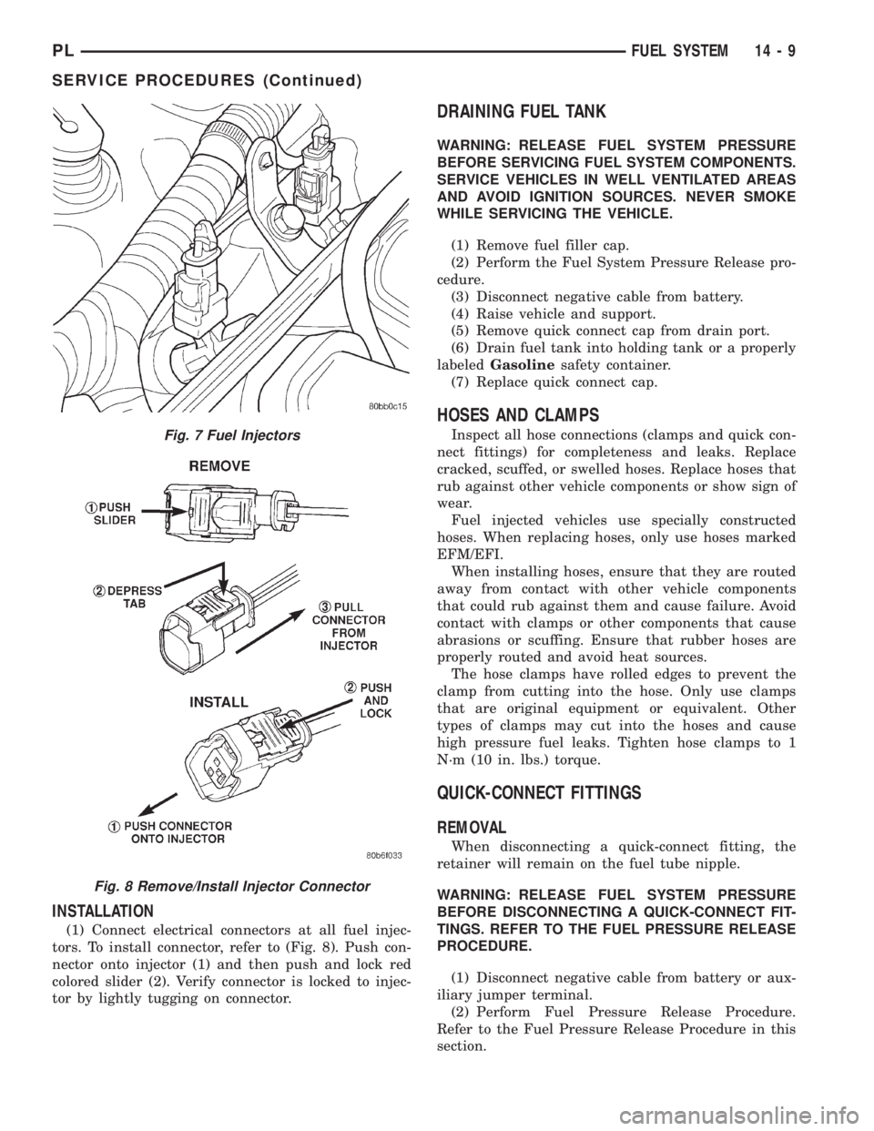
injectors. To remove connector refer to (Fig. 8). Pull
the red colored slider away from injector (1). While
pulling the slider, depress tab (2) and remove connec-
tor (3) from injector. The factory fuel injection wiring
harness is numerically tagged (INJ 1, INJ 2, etc.) for
injector position identification. If harness is not
tagged, make note of wiring location before removal.
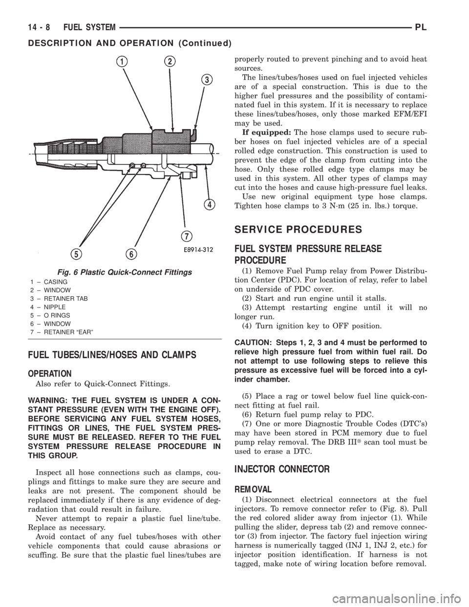
Fig. 6 Plastic Quick-Connect Fittings
1 ± CASING
2 ± WINDOW
3 ± RETAINER TAB
4 ± NIPPLE
5 ± O RINGS
6 ± WINDOW
7 ± RETAINER ªEARº
14 - 8 FUEL SYSTEMPL
DESCRIPTION AND OPERATION (Continued)
Page 830 of 1285
INSTALLATION
(1) Connect electrical connectors at all fuel injec-
tors. To install connector, refer to (Fig. 8). Push con-
nector onto injector (1) and then push and lock red
colored slider (2). Verify connector is locked to injec-
tor by lightly tugging on connector.
DRAINING FUEL TANK
WARNING: RELEASE FUEL SYSTEM PRESSURE
BEFORE SERVICING FUEL SYSTEM COMPONENTS.
SERVICE VEHICLES IN WELL VENTILATED AREAS
AND AVOID IGNITION SOURCES. NEVER SMOKE
WHILE SERVICING THE VEHICLE.
(1) Remove fuel filler cap.
(2) Perform the Fuel System Pressure Release pro-
cedure.
(3) Disconnect negative cable from battery.
(4) Raise vehicle and support.
(5) Remove quick connect cap from drain port.
(6) Drain fuel tank into holding tank or a properly
labeledGasolinesafety container.
(7) Replace quick connect cap.
HOSES AND CLAMPS
Inspect all hose connections (clamps and quick con-
nect fittings) for completeness and leaks. Replace
cracked, scuffed, or swelled hoses. Replace hoses that
rub against other vehicle components or show sign of
wear.
Fuel injected vehicles use specially constructed
hoses. When replacing hoses, only use hoses marked
EFM/EFI.
When installing hoses, ensure that they are routed
away from contact with other vehicle components
that could rub against them and cause failure. Avoid
contact with clamps or other components that cause
abrasions or scuffing. Ensure that rubber hoses are
properly routed and avoid heat sources.
The hose clamps have rolled edges to prevent the
clamp from cutting into the hose. Only use clamps
that are original equipment or equivalent. Other
types of clamps may cut into the hoses and cause
high pressure fuel leaks. Tighten hose clamps to 1
N´m (10 in. lbs.) torque.
QUICK-CONNECT FITTINGS
REMOVAL
When disconnecting a quick-connect fitting, the
retainer will remain on the fuel tube nipple.
WARNING: RELEASE FUEL SYSTEM PRESSURE
BEFORE DISCONNECTING A QUICK-CONNECT FIT-
TINGS. REFER TO THE FUEL PRESSURE RELEASE
PROCEDURE.
(1) Disconnect negative cable from battery or aux-
iliary jumper terminal.
(2) Perform Fuel Pressure Release Procedure.
Refer to the Fuel Pressure Release Procedure in this
section.
Fig. 7 Fuel Injectors
Fig. 8 Remove/Install Injector Connector
PLFUEL SYSTEM 14 - 9
SERVICE PROCEDURES (Continued)
Page 831 of 1285
(3) Squeeze retainer tabs together and pull fuel
tube/quick-connect fitting assembly off of fuel tube
nipple. The retainer will remain on fuel tube.
INSTALLATION
CAUTION: Never install a quick-connect fitting
without the retainer being either on the fuel tube or
already in the quick-connect fitting. In either case,
ensure the retainer locks securely into the quick-
connect fitting by firmly pulling on fuel tube and fit-
ting to ensure it is secured.
(1) Using a clean lint free cloth, clean the fuel tube
nipple and retainer.
(2) Prior to connecting the fitting to the fuel tube,
coat the fuel tube nipple with clean 30 weight engine
oil.
(3) Push the quick-connect fitting over the fuel
tube until theretainer seats and a click is heard.
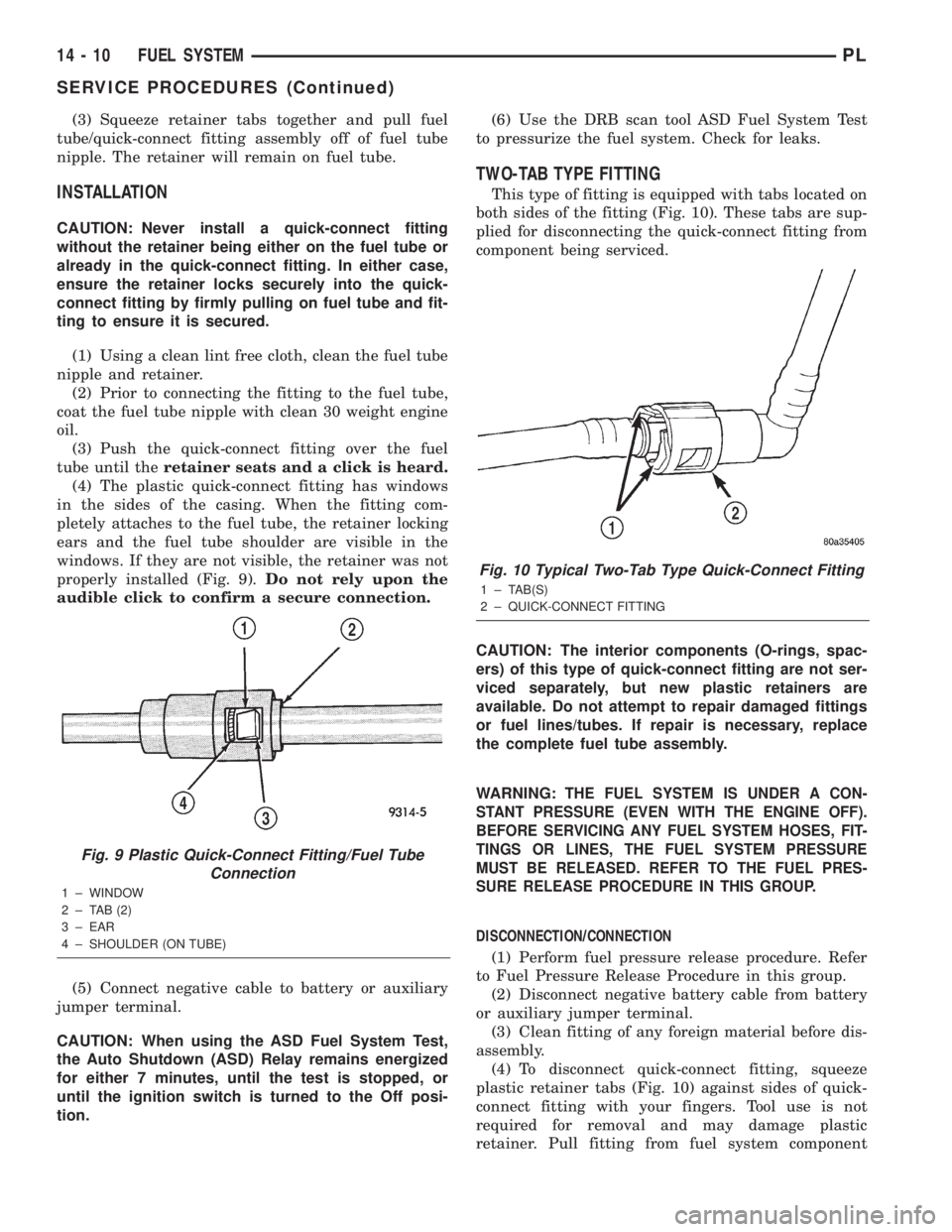
(4) The plastic quick-connect fitting has windows
in the sides of the casing. When the fitting com-
pletely attaches to the fuel tube, the retainer locking
ears and the fuel tube shoulder are visible in the
windows. If they are not visible, the retainer was not
properly installed (Fig. 9).Do not rely upon the
audible click to confirm a secure connection.
(5) Connect negative cable to battery or auxiliary
jumper terminal.
CAUTION: When using the ASD Fuel System Test,
the Auto Shutdown (ASD) Relay remains energized
for either 7 minutes, until the test is stopped, or
until the ignition switch is turned to the Off posi-
tion.(6) Use the DRB scan tool ASD Fuel System Test
to pressurize the fuel system. Check for leaks.
TWO-TAB TYPE FITTING
This type of fitting is equipped with tabs located on
both sides of the fitting (Fig. 10). These tabs are sup-
plied for disconnecting the quick-connect fitting from
component being serviced.
CAUTION: The interior components (O-rings, spac-
ers) of this type of quick-connect fitting are not ser-
viced separately, but new plastic retainers are
available. Do not attempt to repair damaged fittings
or fuel lines/tubes. If repair is necessary, replace
the complete fuel tube assembly.
WARNING:
THE FUEL SYSTEM IS UNDER A CON-
STANT PRESSURE (EVEN WITH THE ENGINE OFF).
BEFORE SERVICING ANY FUEL SYSTEM HOSES, FIT-
TINGS OR LINES, THE FUEL SYSTEM PRESSURE
MUST BE RELEASED. REFER TO THE FUEL PRES-
SURE RELEASE PROCEDURE IN THIS GROUP.
DISCONNECTION/CONNECTION
(1) Perform fuel pressure release procedure. Refer
to Fuel Pressure Release Procedure in this group.
(2) Disconnect negative battery cable from battery
or auxiliary jumper terminal.
(3) Clean fitting of any foreign material before dis-
assembly.
(4) To disconnect quick-connect fitting, squeeze
plastic retainer tabs (Fig. 10) against sides of quick-
connect fitting with your fingers. Tool use is not
required for removal and may damage plastic
retainer. Pull fitting from fuel system component
Fig. 9 Plastic Quick-Connect Fitting/Fuel Tube
Connection
1 ± WINDOW
2 ± TAB (2)
3 ± EAR
4 ± SHOULDER (ON TUBE)
Fig. 10 Typical Two-Tab Type Quick-Connect Fitting
1 ± TAB(S)
2 ± QUICK-CONNECT FITTING
14 - 10 FUEL SYSTEMPL
SERVICE PROCEDURES (Continued)
Page 833 of 1285

REMOVAL AND INSTALLATION
AUTOMATIC SHUTDOWN RELAY
The relay is located in the Power Distribution Cen-
ter (PDC) (Fig. 12). The PDC is located next to the
battery in the engine compartment. For the location
of the relay within the PDC, refer to the PDC cover
for location. Check electrical terminals for corrosion
and repair as necessary.
FUEL PUMP RELAY
The fuel pump relay is located in the PDC. The
inside top of the PDC cover has a label showing relay
and fuse location.
FUEL PUMP MODULE
REMOVAL
WARNING: RELEASE FUEL SYSTEM PRESSURE
BEFORE SERVICING FUEL SYSTEM COMPONENTS.
SERVICE VEHICLES IN WELL VENTILATED AREAS
AND AVOID IGNITION SOURCES. NEVER SMOKE
WHILE SERVICING THE VEHICLE.
(1) Drain the fuel. Refer to Draining Fuel Tank in
the Fuel Tank section of this group.
WARNING: THE FUEL RESERVOIR OF THE FUEL
PUMP MODULE DOES NOT EMPTY OUT WHEN THE
TANK IS DRAINED. THE FUEL IN THE RESERVOIR
WILL SPILL OUT WHEN THE MODULE IS
REMOVED.
(2) Remove fuel tank, refer to the Fuel Tank
removal/installation section.
(3) Lower tank.(4) Use Special Tool 6856 to remove fuel pump
module locknut (Fig. 15).
(5) Remove fuel pump and O-ring seal from tank.
Discard old seal.
INSTALLATION
(1) Wipe seal area of tank clean and place a new
seal in position in the tank opening.
(2) Position fuel pump in the tank. Make sure the
alignment tab on the underside of the fuel pump
module flange sits in the notch on the fuel tank (Fig.
14).
(3) Position the locknut over the fuel pump mod-
ule.
Fig. 12 Power Distribution Center (PDC)
Fig. 13 Fuel Pump Module Removal
1 ± FUEL FILTER/PRESSURE REGULATOR
2 ± FUEL LINE
3 ± LOCKNUT
Fig. 14 Alignment Tab
14 - 12 FUEL SYSTEMPL
Page 837 of 1285

(3) Install retaining clip.
(4) Apply a light coating of clean engine oil to the
O-ring on the nozzle end of each injector.
(5) Insert fuel injector nozzles into openings in
intake manifold. Seat the injectors in place. Tighten
fuel rail mounting screws to 22.5 N´m63 N´m
(200630 in. lbs.).
(6) Attach electrical connectors to fuel injectors,
refer to the fuel injector connector section for electri-
cal connector installation.
(7) Connect fuel supply tube to fuel rail. Refer to
Quick Connect Fittings in the Fuel Delivery Section
of this Group.
FUEL TANK
REMOVAL
(1) Disconnect the negative battery cable (Fig. 28).
(2) Perform fuel system pressure release, refer to
the fuel system pressure release procedure in this
section.
(3) Raise and support vehicle on hoist.
(4) Disconnect vapor line from EVAP canister tube.
(5) Remove EVAP canister (Fig. 29).
(6) Drain fuel tank. Remove the drain port cap and
remove fuel. Drain fuel tank into holding tank or a
properly labeledGasolinesafety container. Reinstall
drain port cap when done draining fuel (Fig. 30).
Fig. 25 Fuel Rail and Injectors
1 ± FUEL SUPPLY LINE
2 ± FUEL LINE QUICK-CONNECTS
3 ± IGNITION COIL
4 ± FUEL RAIL
5 ± FUEL INJECTOR
Fig. 26 Fuel Injector Retainer
1 ± RETAINER
2 ± FUEL RAIL
3 ± FUEL INJECTOR
Fig. 27 Fuel Injector O-Rings
1 ± FUEL INJECTOR
2 ± NOZZLE
3 ± TOP (FUEL ENTRY)
Fig. 28 Battery Cable
14 - 16 FUEL SYSTEMPL
REMOVAL AND INSTALLATION (Continued)
Page 838 of 1285

(7) Disconnect fuel pump module electrical connec-
tor and ground wire (Fig. 31).
(8) Disconnect the fuel tube from Fuel Filter/Reg-
ulator. Refer to Quick Connect Fittings in the Fuel
Delivery section of this group.
(9) Disconnect fuel filler tube and filler vent tube
from filler hose at fuel tank.
(10) Support tank with transmission jack. Loosen
tank mounting straps and lower tank slightly.
(11) Remove tank mounting straps and lower tank.
INSTALLATION
(1) Position fuel tank on transmission jack.
(2) Raise tank into position.
(3) Tighten fuel tank strap nuts to 22.5 N´m (200
in. lbs.) torque. Remove transmission jack. Ensure
straps are not twisted or bent.(4) Connect fuel filler tube tank inlet nipple.
Tighten clamp.
(5) Connect EVAP vent hose.
(6) Attach fuel tubes to pump module and chassis
fuel tube. Refer to Quick Connect Fittings in the Fuel
Delivery section of this Group.
(7) Attach electrical connector and ground wire to
fuel pump module.
(8) Install vapor lines to EVAP canister.
(9) Install EVAP canister.
(10) Lower vehicle.
(11) Fill fuel tank, install filler cap, and connect
battery cable.
CAUTION: When using the ASD Fuel System Test,
the Auto Shutdown (ASD) Relay remains energized
for either 7 minutes, until the test is stopped, or
until the ignition switch is turned to the Off posi-
tion.
(12) Use the DRB scan tool ASD Fuel System Test
to pressurize the fuel system. Check for leaks.
FUEL FILLER NECK
REMOVAL
(1) Loosen fuel filler tube cap.
(2) Remove fuel filler neck screws (Fig. 32).
(3) Raise and support vehicle.
(4) Remove splash shield from wheel well.
(5) Disconnect fuel fill vapor tube.
(6) Disconnect fuel filler tube from fuel tank.
(7) Remove groundstrap from body.
(8) Remove filler neck (Fig. 33).
Fig. 29 EVAP Canister
Fig. 30 Fuel Tank
Fig. 31 Pump Module Electrical Connector
1 ± ELECTRICAL CONNECTOR
2 ± FUEL LINE
PLFUEL SYSTEM 14 - 17
REMOVAL AND INSTALLATION (Continued)
Page 841 of 1285
SPECIFICATIONS
TORQUE
DESCRIPTION TORQUE
Accelerator Pedal to Dash Nuts......... 12N´m
(105 in. lbs.)
Fuel Pump Module Locknut . . . 55 N´m (40 ft. lbs.)
Fuel Tank Strap Bolts.....22.5 N´m (200 in. lbs.)
Fuel Rail Bolts............ 23N´m(195 in. lbs.)
Ignition Coil Mounting Bolts . . 11 N´m (95 in. lbs.)
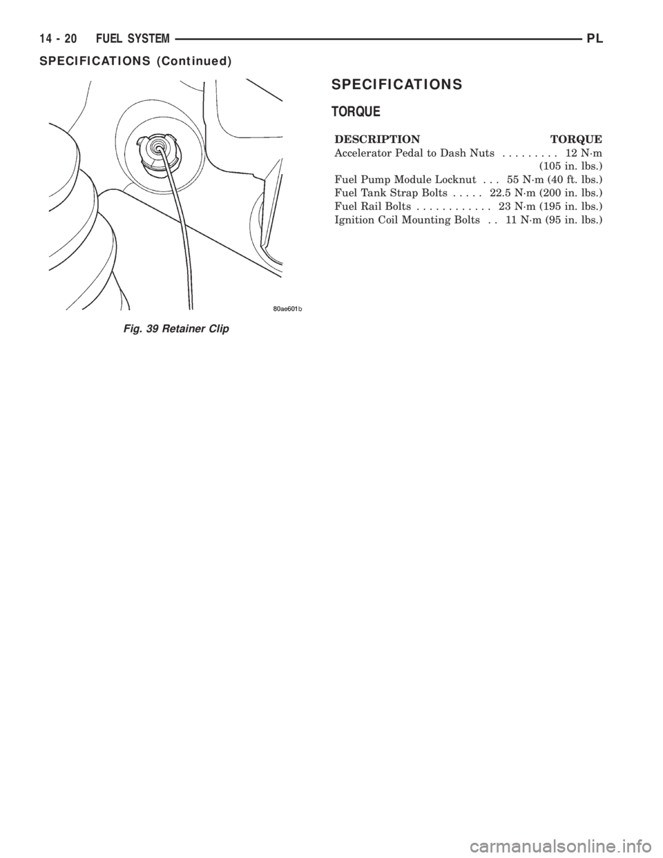
Fig. 39 Retainer Clip
14 - 20 FUEL SYSTEMPL
SPECIFICATIONS (Continued)