2000 DODGE NEON ignition
[x] Cancel search: ignitionPage 990 of 1285
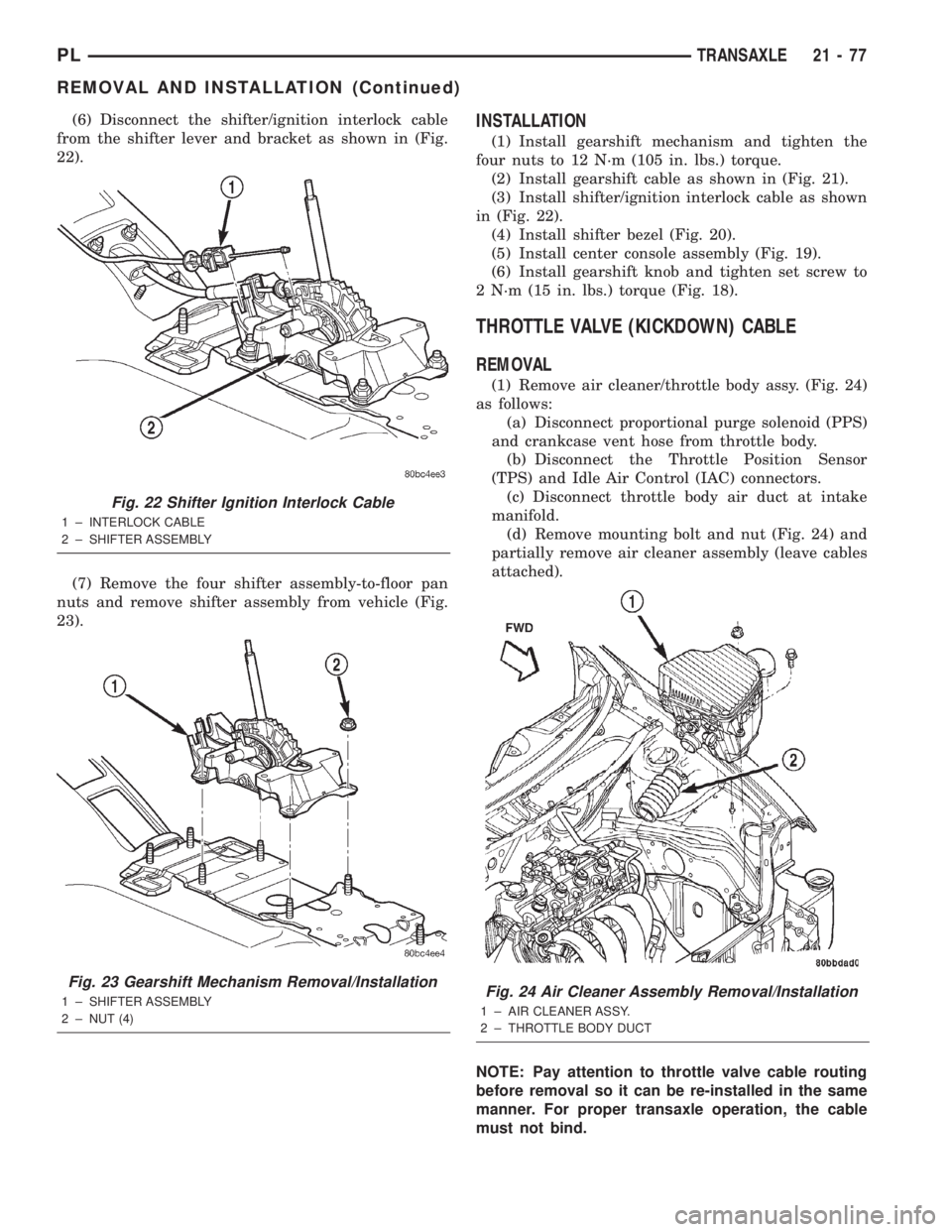
(6) Disconnect the shifter/ignition interlock cable
from the shifter lever and bracket as shown in (Fig.
22).
(7) Remove the four shifter assembly-to-floor pan
nuts and remove shifter assembly from vehicle (Fig.
23).INSTALLATION
(1) Install gearshift mechanism and tighten the
four nuts to 12 N´m (105 in. lbs.) torque.
(2) Install gearshift cable as shown in (Fig. 21).
(3) Install shifter/ignition interlock cable as shown
in (Fig. 22).
(4) Install shifter bezel (Fig. 20).
(5) Install center console assembly (Fig. 19).
(6) Install gearshift knob and tighten set screw to
2 N´m (15 in. lbs.) torque (Fig. 18).
THROTTLE VALVE (KICKDOWN) CABLE
REMOVAL
(1) Remove air cleaner/throttle body assy. (Fig. 24)
as follows:
(a) Disconnect proportional purge solenoid (PPS)
and crankcase vent hose from throttle body.
(b) Disconnect the Throttle Position Sensor
(TPS) and Idle Air Control (IAC) connectors.
(c) Disconnect throttle body air duct at intake
manifold.
(d) Remove mounting bolt and nut (Fig. 24) and
partially remove air cleaner assembly (leave cables
attached).
NOTE: Pay attention to throttle valve cable routing
before removal so it can be re-installed in the same
manner. For proper transaxle operation, the cable
must not bind.
Fig. 22 Shifter Ignition Interlock Cable
1 ± INTERLOCK CABLE
2 ± SHIFTER ASSEMBLY
Fig. 23 Gearshift Mechanism Removal/Installation
1 ± SHIFTER ASSEMBLY
2 ± NUT (4)Fig. 24 Air Cleaner Assembly Removal/Installation
1 ± AIR CLEANER ASSY.
2 ± THROTTLE BODY DUCT
PLTRANSAXLE 21 - 77
REMOVAL AND INSTALLATION (Continued)
Page 993 of 1285
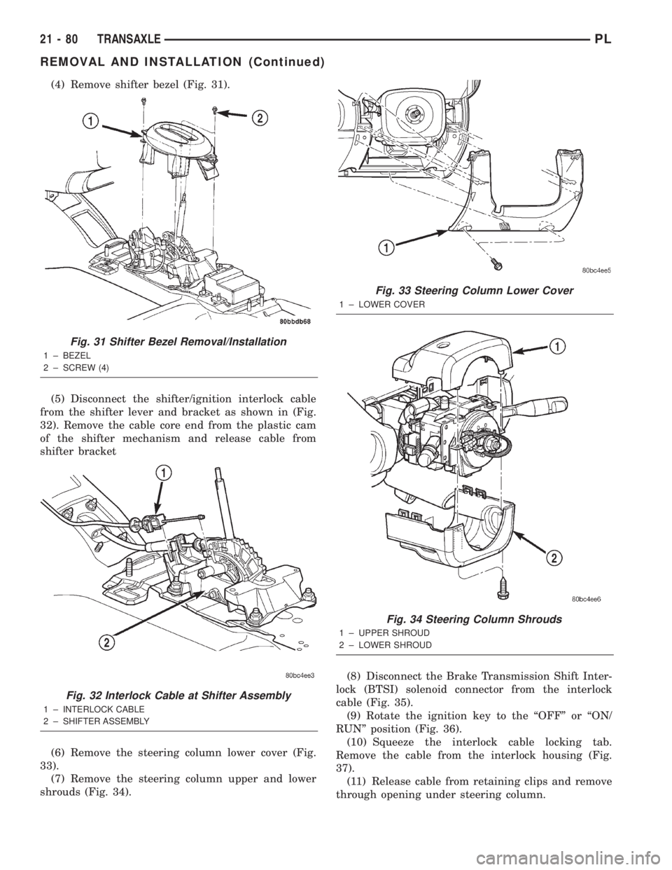
(4) Remove shifter bezel (Fig. 31).
(5) Disconnect the shifter/ignition interlock cable
from the shifter lever and bracket as shown in (Fig.
32). Remove the cable core end from the plastic cam
of the shifter mechanism and release cable from
shifter bracket
(6) Remove the steering column lower cover (Fig.
33).
(7) Remove the steering column upper and lower
shrouds (Fig. 34).(8) Disconnect the Brake Transmission Shift Inter-
lock (BTSI) solenoid connector from the interlock
cable (Fig. 35).
(9) Rotate the ignition key to the ªOFFº or ªON/
RUNº position (Fig. 36).
(10) Squeeze the interlock cable locking tab.
Remove the cable from the interlock housing (Fig.
37).
(11) Release cable from retaining clips and remove
through opening under steering column.
Fig. 31 Shifter Bezel Removal/Installation
1 ± BEZEL
2 ± SCREW (4)
Fig. 32 Interlock Cable at Shifter Assembly
1 ± INTERLOCK CABLE
2 ± SHIFTER ASSEMBLY
Fig. 33 Steering Column Lower Cover
1 ± LOWER COVER
Fig. 34 Steering Column Shrouds
1 ± UPPER SHROUD
2 ± LOWER SHROUD
21 - 80 TRANSAXLEPL
REMOVAL AND INSTALLATION (Continued)
Page 994 of 1285
INSTALLATION
CAUTION: When installing interlock cable assem-
bly, care must be taken not to bend exposed cable
wire and slug at shifter end of cable.(1) Route interlock cable through hole in instru-
ment panel below steering column and around to
gear shifter assembly.
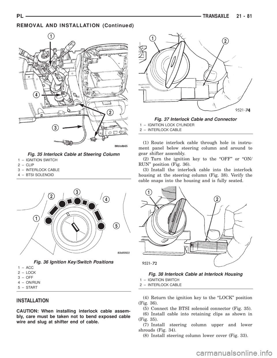
(2) Turn the ignition key to the ªOFFº or ªON/
RUNº position (Fig. 36).
(3) Install the interlock cable into the interlock
housing at the steering column (Fig. 38). Verify the
cable snaps into the housing and is fully seated.
(4) Return the ignition key to the ªLOCKº position
(Fig. 36).
(5) Connect the BTSI solenoid connector (Fig. 35).
(6) Install cable into retaining clips as shown in
(Fig. 35).
(7) Install steering column upper and lower
shrouds (Fig. 34).
(8) Install steering column lower cover (Fig. 33).
Fig. 35 Interlock Cable at Steering Column
1 ± IGNITION SWITCH
2 ± CLIP
3 ± INTERLOCK CABLE
4 ± BTSI SOLENOID
Fig. 36 Ignition Key/Switch Positions
1 ± ACC
2 ± LOCK
3 ± OFF
4 ± ON/RUN
5±START
Fig. 37 Interlock Cable and Connector
1 ± IGNITION LOCK CYLINDER
2 ± INTERLOCK CABLE
Fig. 38 Interlock Cable at Interlock Housing
1 ± IGNITION SWITCH
2 ± INTERLOCK CABLE
PLTRANSAXLE 21 - 81
REMOVAL AND INSTALLATION (Continued)
Page 995 of 1285
(9) Verify that shifter is in gated ªPARKº.
(10) Install the cable core end to the plastic cam of
the shifter mechanism. Snap the shifter/ignition
interlock cable end fitting into the groove in the gear-
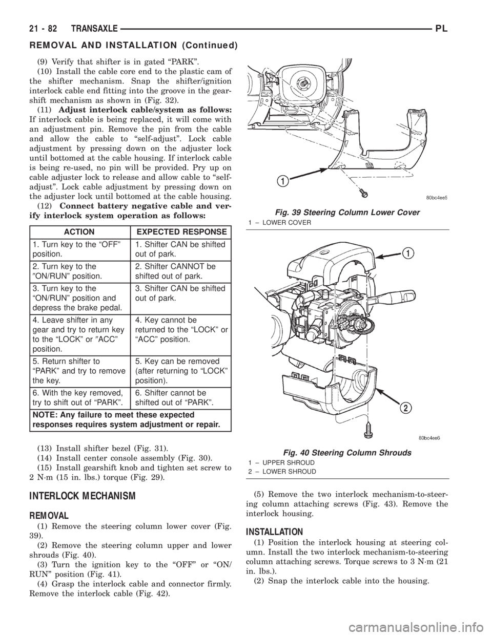
shift mechanism as shown in (Fig. 32).
(11)Adjust interlock cable/system as follows:
If interlock cable is being replaced, it will come with
an adjustment pin. Remove the pin from the cable
and allow the cable to ªself-adjustº. Lock cable
adjustment by pressing down on the adjuster lock
until bottomed at the cable housing. If interlock cable
is being re-used, no pin will be provided. Pry up on
cable adjuster lock to release and allow cable to ªself-
adjustº. Lock cable adjustment by pressing down on
the adjuster lock until bottomed at the cable housing.
(12)Connect battery negative cable and ver-
ify interlock system operation as follows:
(13) Install shifter bezel (Fig. 31).
(14) Install center console assembly (Fig. 30).
(15) Install gearshift knob and tighten set screw to
2 N´m (15 in. lbs.) torque (Fig. 29).
INTERLOCK MECHANISM
REMOVAL
(1) Remove the steering column lower cover (Fig.
39).
(2) Remove the steering column upper and lower
shrouds (Fig. 40).
(3) Turn the ignition key to the ªOFFº or ªON/
RUNº position (Fig. 41).
(4) Grasp the interlock cable and connector firmly.
Remove the interlock cable (Fig. 42).(5) Remove the two interlock mechanism-to-steer-
ing column attaching screws (Fig. 43). Remove the
interlock housing.INSTALLATION
(1) Position the interlock housing at steering col-
umn. Install the two interlock mechanism-to-steering
column attaching screws. Torque screws to 3 N´m (21
in. lbs.).
(2) Snap the interlock cable into the housing.
ACTION EXPECTED RESPONSE
1. Turn key to the ªOFFº
position.1. Shifter CAN be shifted
out of park.
2. Turn key to the
9ON/RUNº position.2. Shifter CANNOT be
shifted out of park.
3. Turn key to the
ªON/RUNº position and
depress the brake pedal.3. Shifter CAN be shifted
out of park.
4. Leave shifter in any
gear and try to return key
to the ªLOCKº or9ACCº
position.4. Key cannot be
returned to the ªLOCKº or
ªACCº position.
5. Return shifter to
ªPARKº and try to remove
the key.5. Key can be removed
(after returning to ªLOCKº
position).
6. With the key removed,
try to shift out of ªPARKº.6. Shifter cannot be
shifted out of ªPARKº.
NOTE: Any failure to meet these expected
responses requires system adjustment or repair.
Fig. 39 Steering Column Lower Cover
1 ± LOWER COVER
Fig. 40 Steering Column Shrouds
1 ± UPPER SHROUD
2 ± LOWER SHROUD
21 - 82 TRANSAXLEPL
REMOVAL AND INSTALLATION (Continued)
Page 996 of 1285
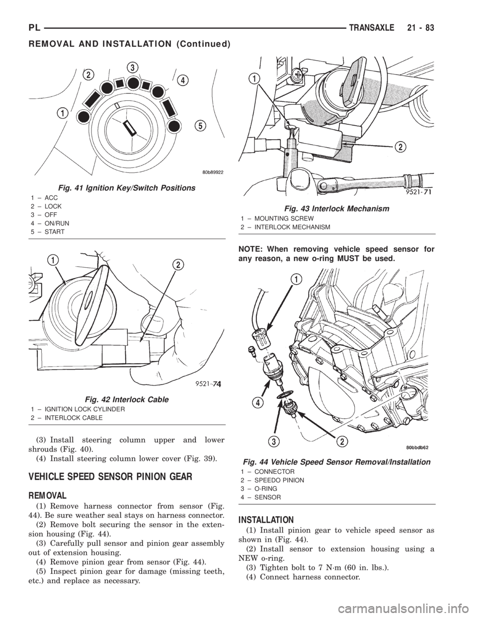
(3) Install steering column upper and lower
shrouds (Fig. 40).
(4) Install steering column lower cover (Fig. 39).
VEHICLE SPEED SENSOR PINION GEAR
REMOVAL
(1) Remove harness connector from sensor (Fig.
44). Be sure weather seal stays on harness connector.
(2) Remove bolt securing the sensor in the exten-
sion housing (Fig. 44).
(3) Carefully pull sensor and pinion gear assembly
out of extension housing.
(4) Remove pinion gear from sensor (Fig. 44).
(5) Inspect pinion gear for damage (missing teeth,
etc.) and replace as necessary.NOTE: When removing vehicle speed sensor for
any reason, a new o-ring MUST be used.
INSTALLATION
(1) Install pinion gear to vehicle speed sensor as
shown in (Fig. 44).
(2) Install sensor to extension housing using a
NEW o-ring.
(3) Tighten bolt to 7 N´m (60 in. lbs.).
(4) Connect harness connector.
Fig. 41 Ignition Key/Switch Positions
1 ± ACC
2 ± LOCK
3 ± OFF
4 ± ON/RUN
5±START
Fig. 42 Interlock Cable
1 ± IGNITION LOCK CYLINDER
2 ± INTERLOCK CABLE
Fig. 43 Interlock Mechanism
1 ± MOUNTING SCREW
2 ± INTERLOCK MECHANISM
Fig. 44 Vehicle Speed Sensor Removal/Installation
1 ± CONNECTOR
2 ± SPEEDO PINION
3 ± O-RING
4 ± SENSOR
PLTRANSAXLE 21 - 83
REMOVAL AND INSTALLATION (Continued)
Page 1088 of 1285
EMISSION CONTROL SYSTEMS
TABLE OF CONTENTS
page page
ON-BOARD DIAGNOSTICS................... 1 EVAPORATIVE EMISSION CONTROLS......... 25
ON-BOARD DIAGNOSTICS
TABLE OF CONTENTS
page page
DESCRIPTION AND OPERATION
SYSTEM DESCRIPTION....................1
TASK MANAGER..........................2
MALFUNCTION INDICATOR LAMP (MIL)........5
DRB III STATE DISPLAY TEST MODE..........5
DRB III CIRCUIT ACTUATION TEST MODE......5
DIAGNOSTIC TROUBLE CODES..............5
DIAGNOSTIC TROUBLE CODE
DESCRIPTIONS.........................6MONITORED SYSTEMS....................15
TRIP DEFINITION........................19
MONITORED COMPONENT.................19
NON-MONITORED CIRCUITS...............23
HIGH AND LOW LIMITS....................24
LOAD VALUE............................24
DESCRIPTION AND OPERATION
SYSTEM DESCRIPTION
DESCRIPTION
OBD II requires that vehicles falling under OBD II
guidelines utilize the following system monitors:
²Comprehensive Component Monitor (inputs/out-
puts for powertrain management that affect emis-
sions, but do not have a specific major monitor)
²Fuel Control Monitor (fuel compensation
required to maintain stoichiometric ratio rich/lean)
²Misfire Monitor (change in crankshaft speed)
²Oxygen Sensor Heater Monitor (response and
performance of oxygen sensors)
²Catalyst Monitor (Performance and efficiency of
catalyst)
²Evaporative Emissions Monitor (performance of
and leaks from EVAP system)
²Exhaust Gas Recirculation Monitor (flow perfor-
mance of EGR system)
The software was rewritten to enable the PCM to
carry out the responsibilities to meet these required
guidelines. The PCM now contains a Task Manager.
OPERATION
The Powertrain Control Module (PCM) monitors
many different circuits in the fuel injection, ignition,
emission and engine systems. If the PCM senses a
problem with a monitored circuit often enough to
indicate an actual problem, it stores a Diagnostic
Trouble Code (DTC) in the PCM's memory. If the
code applies to a non-emissions related component or
system, and the problem is repaired or ceases to
exist, the PCM cancels the code after 40 warmup
cycles. Diagnostic trouble codes that affect vehicle
emissions illuminate the Malfunction Indicator Lamp
(MIL). Refer to Malfunction Indicator Lamp in this
section.
Certain criteria must be met before the PCM
stores a DTC in memory. The criteria may be a spe-
cific range of engine RPM, engine temperature,
and/or input voltage to the PCM.
The PCM might not store a DTC for a monitored
circuit even though a malfunction has occurred. This
may happen because one of the DTC criteria for the
circuit has not been met.For example, assume the
diagnostic trouble code criteria requires the PCM to
monitor the circuit only when the engine operates
between 750 and 2000 RPM. Suppose the sensor's
output circuit shorts to ground when engine operates
above 2400 RPM (resulting in 0 volt input to the
PLEMISSION CONTROL SYSTEMS 25 - 1
Page 1093 of 1285
OPERATION
BULB CHECK
Each time the ignition key is turned to the ON
position, the malfunction indicator (check engine)
lamp on the instrument panel should illuminate for
approximately 2 seconds then go out. This is done for
a bulb check.
OBTAINING DTC'S USING DRB SCAN TOOL
(1) Connect the DRB scan tool to the data link
(diagnostic) connector. This connector is located inthe passenger compartment; at the lower edge of
instrument panel; near the steering column.
(2) Turn the ignition switch on and access the
ªRead Faultº screen.
(3) Record all the DTC's and ªfreeze frameº infor-
mation shown on the DRB scan tool.
(4) To erase DTC's, use the ªErase Trouble Codeº
data screen on the DRB scan tool.Do not erase any
DTC's until problems have been investigated
and repairs have been performed.
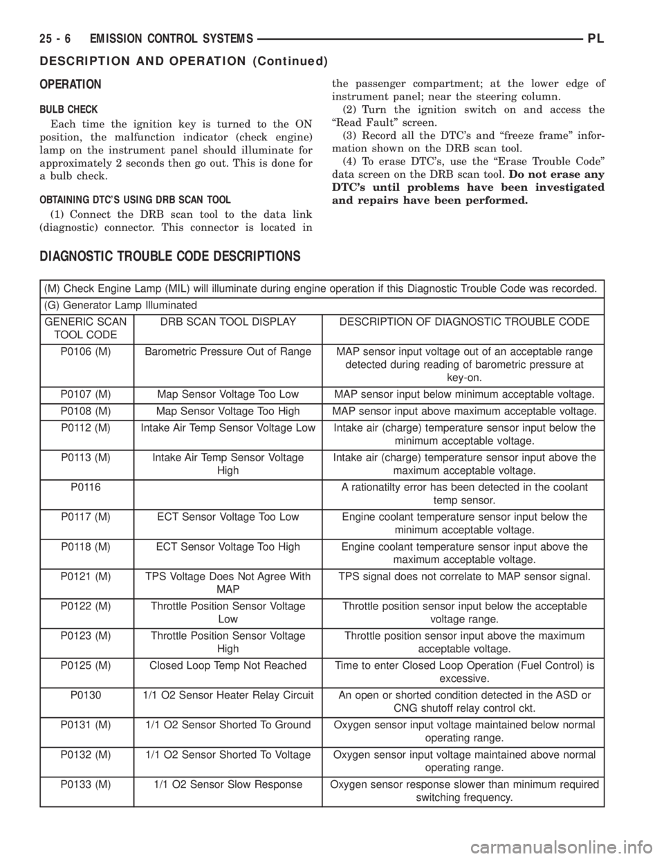
DIAGNOSTIC TROUBLE CODE DESCRIPTIONS
(M) Check Engine Lamp (MIL) will illuminate during engine operation if this Diagnostic Trouble Code was recorded.
(G) Generator Lamp Illuminated
GENERIC SCAN
TOOL CODEDRB SCAN TOOL DISPLAY DESCRIPTION OF DIAGNOSTIC TROUBLE CODE
P0106 (M) Barometric Pressure Out of Range MAP sensor input voltage out of an acceptable range
detected during reading of barometric pressure at
key-on.
P0107 (M) Map Sensor Voltage Too Low MAP sensor input below minimum acceptable voltage.
P0108 (M) Map Sensor Voltage Too High MAP sensor input above maximum acceptable voltage.
P0112 (M) Intake Air Temp Sensor Voltage Low Intake air (charge) temperature sensor input below the
minimum acceptable voltage.
P0113 (M) Intake Air Temp Sensor Voltage
HighIntake air (charge) temperature sensor input above the
maximum acceptable voltage.
P0116 A rationatilty error has been detected in the coolant
temp sensor.
P0117 (M) ECT Sensor Voltage Too Low Engine coolant temperature sensor input below the
minimum acceptable voltage.
P0118 (M) ECT Sensor Voltage Too High Engine coolant temperature sensor input above the
maximum acceptable voltage.
P0121 (M) TPS Voltage Does Not Agree With
MAPTPS signal does not correlate to MAP sensor signal.
P0122 (M) Throttle Position Sensor Voltage
LowThrottle position sensor input below the acceptable
voltage range.
P0123 (M) Throttle Position Sensor Voltage
HighThrottle position sensor input above the maximum
acceptable voltage.
P0125 (M) Closed Loop Temp Not Reached Time to enter Closed Loop Operation (Fuel Control) is
excessive.
P0130 1/1 O2 Sensor Heater Relay Circuit An open or shorted condition detected in the ASD or
CNG shutoff relay control ckt.
P0131 (M) 1/1 O2 Sensor Shorted To Ground Oxygen sensor input voltage maintained below normal
operating range.
P0132 (M) 1/1 O2 Sensor Shorted To Voltage Oxygen sensor input voltage maintained above normal
operating range.
P0133 (M) 1/1 O2 Sensor Slow Response Oxygen sensor response slower than minimum required
switching frequency.
25 - 6 EMISSION CONTROL SYSTEMSPL
DESCRIPTION AND OPERATION (Continued)
Page 1096 of 1285
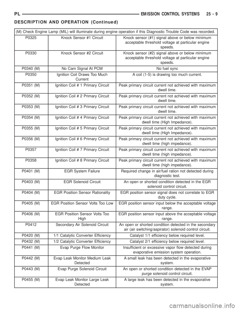
(M) Check Engine Lamp (MIL) will illuminate during engine operation if this Diagnostic Trouble Code was recorded.
P0325 Knock Sensor #1 Circuit Knock sensor (#1) signal above or below minimum
acceptable threshold voltage at particular engine
speeds.
P0330 Knock Sensor #2 Circuit Knock sensor (#2) signal above or below minimum
acceptable threshold voltage at particular engine
speeds.
P0340 (M) No Cam Signal At PCM No fuel sync
P0350 Ignition Coil Draws Too Much
CurrentA coil (1-5) is drawing too much current.
P0351 (M) Ignition Coil # 1 Primary Circuit Peak primary circuit current not achieved with maximum
dwell time.
P0352 (M) Ignition Coil # 2 Primary Circuit Peak primary circuit current not achieved with maximum
dwell time.
P0353 (M) Ignition Coil # 3 Primary Circuit Peak primary circuit current not achieved with maximum
dwell time.
P0354 (M) Ignition Coil # 4 Primary Circuit Peak primary circuit current not achieved with maximum
dwell time (High Impedance).
P0355 (M) Ignition Coil # 5 Primary Circuit Peak primary circuit current not achieved with maximum
dwell time (High Impedance).
P0356 (M) Ignition Coil # 6 Primary Circuit Peak primary circuit current not achieved with maximum
dwell time (high impedance).
P0357 Ignition Coil # 7 Primary Circuit Peak primary circuit current not achieved with maximum
dwell time (high impedance).
P0358 Ignition Coil # 8 Primary Circuit Peak primary circuit current not achieved with maximum
dwell time (high impedance).
P0401 (M) EGR System Failure Required change in air/fuel ration not detected during
diagnostic test.
P0403 (M) EGR Solenoid Circuit An open or shorted condition detected in the EGR
solenoid control circuit.
P0404 (M) EGR Position Sensor Rationality EGR position sensor signal does not correlate to EGR
duty cycle.
P0405 (M) EGR Position Sensor Volts Too Low EGR position sensor input below the acceptable voltage
range.
P0406 (M) EGR Position Sensor Volts Too
HighEGR position sensor input above the acceptable voltage
range.
P0412 Secondary Air Solenoid Circuit An open or shorted condition detected in the secondary
air (air switching/aspirator) solenoid control circuit.
P0420 (M) 1/1 Catalytic Converter Efficiency Catalyst 1/1 efficiency below required level.
P0432 (M) 1/2 Catalytic Converter Efficiency Catalyst 2/1 efficiency below required level.
P0441 (M) Evap Purge Flow Monitor Insufficient or excessive vapor flow detected during
evaporative emission system operation.
P0442 (M) Evap Leak Monitor Medium Leak
DetectedA small leak has been detected in the evaporative
system.
P0443 (M) Evap Purge Solenoid Circuit An open or shorted condition detected in the EVAP
purge solenoid control circuit.
P0455 (M) Evap Leak Monitor Large Leak
DetectedA large leak has been detected in the evaporative
system.
PLEMISSION CONTROL SYSTEMS 25 - 9
DESCRIPTION AND OPERATION (Continued)