2000 DODGE NEON ignition
[x] Cancel search: ignitionPage 754 of 1285
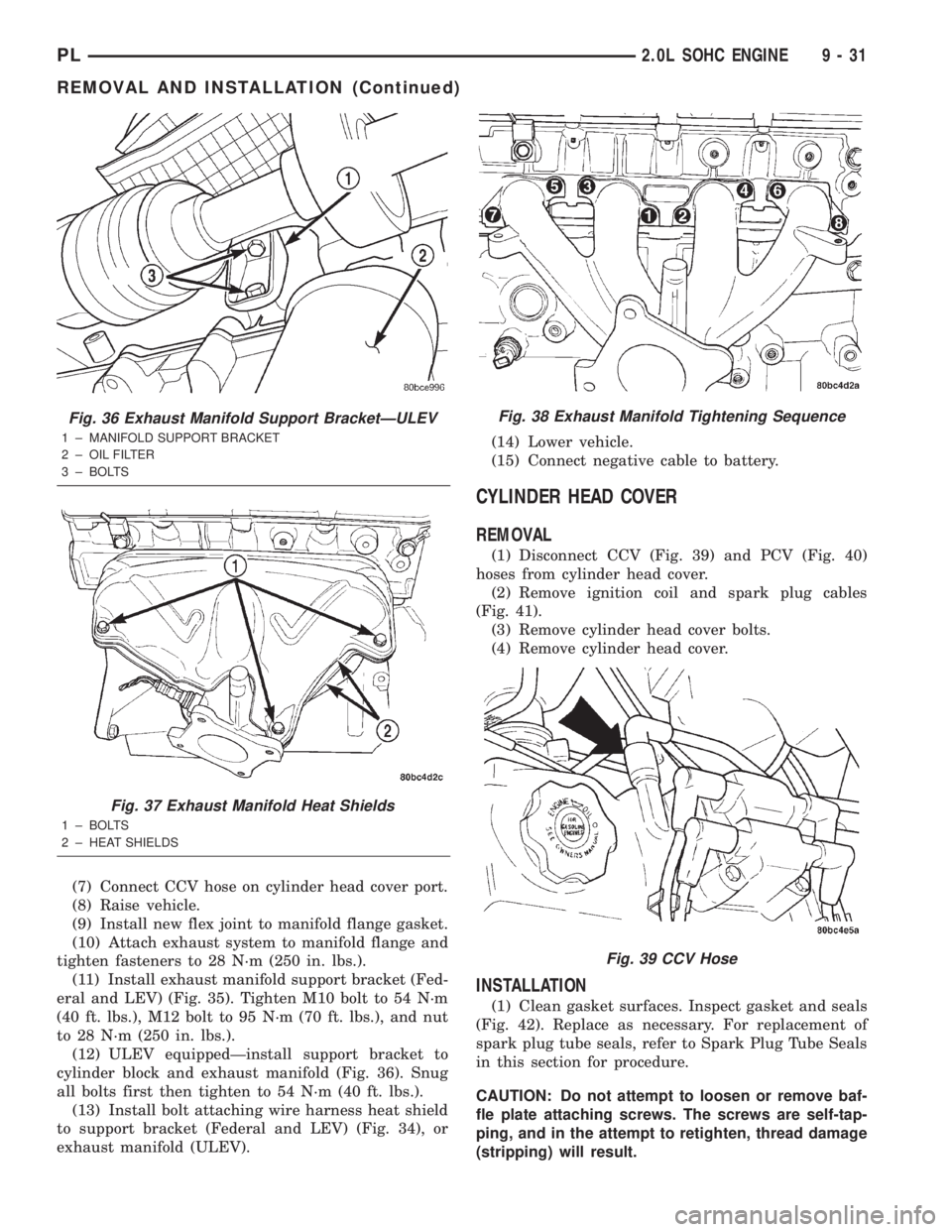
(7) Connect CCV hose on cylinder head cover port.
(8) Raise vehicle.
(9) Install new flex joint to manifold flange gasket.
(10) Attach exhaust system to manifold flange and
tighten fasteners to 28 N´m (250 in. lbs.).
(11) Install exhaust manifold support bracket (Fed-
eral and LEV) (Fig. 35). Tighten M10 bolt to 54 N´m
(40 ft. lbs.), M12 bolt to 95 N´m (70 ft. lbs.), and nut
to 28 N´m (250 in. lbs.).
(12) ULEV equippedÐinstall support bracket to
cylinder block and exhaust manifold (Fig. 36). Snug
all bolts first then tighten to 54 N´m (40 ft. lbs.).
(13) Install bolt attaching wire harness heat shield
to support bracket (Federal and LEV) (Fig. 34), or
exhaust manifold (ULEV).(14) Lower vehicle.
(15) Connect negative cable to battery.
CYLINDER HEAD COVER
REMOVAL
(1) Disconnect CCV (Fig. 39) and PCV (Fig. 40)
hoses from cylinder head cover.
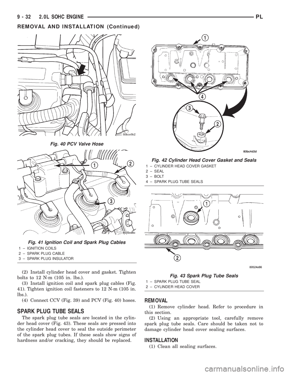
(2) Remove ignition coil and spark plug cables
(Fig. 41).
(3) Remove cylinder head cover bolts.
(4) Remove cylinder head cover.
INSTALLATION
(1) Clean gasket surfaces. Inspect gasket and seals
(Fig. 42). Replace as necessary. For replacement of
spark plug tube seals, refer to Spark Plug Tube Seals
in this section for procedure.
CAUTION: Do not attempt to loosen or remove baf-
fle plate attaching screws. The screws are self-tap-
ping, and in the attempt to retighten, thread damage
(stripping) will result.
Fig. 36 Exhaust Manifold Support BracketÐULEV
1 ± MANIFOLD SUPPORT BRACKET
2 ± OIL FILTER
3 ± BOLTS
Fig. 37 Exhaust Manifold Heat Shields
1 ± BOLTS
2 ± HEAT SHIELDS
Fig. 38 Exhaust Manifold Tightening Sequence
Fig. 39 CCV Hose
PL2.0L SOHC ENGINE 9 - 31
REMOVAL AND INSTALLATION (Continued)
Page 755 of 1285
(2) Install cylinder head cover and gasket. Tighten
bolts to 12 N´m (105 in. lbs.).
(3) Install ignition coil and spark plug cables (Fig.
41). Tighten ignition coil fasteners to 12 N´m (105 in.
lbs.).
(4) Connect CCV (Fig. 39) and PCV (Fig. 40) hoses.
SPARK PLUG TUBE SEALS
The spark plug tube seals are located in the cylin-
der head cover (Fig. 43). These seals are pressed into
the cylinder head cover to seal the outside perimeter
of the spark plug tubes. If these seals show signs of
hardness and/or cracking, they should be replaced.
REMOVAL
(1) Remove cylinder head. Refer to procedure in
this section.
(2) Using an appropriate tool, carefully remove
spark plug tube seals. Care should be taken not to
damage cylinder head cover sealing surfaces.
INSTALLATION
(1) Clean all sealing surfaces.
Fig. 40 PCV Valve Hose
Fig. 41 Ignition Coil and Spark Plug Cables
1 ± IGNITION COILS
2 ± SPARK PLUG CABLE
3 ± SPARK PLUG INSULATOR
Fig. 42 Cylinder Head Cover Gasket and Seals
1 ± CYLINDER HEAD COVER GASKET
2 ± SEAL
3 ± BOLT
4 ± SPARK PLUG TUBE SEALS
Fig. 43 Spark Plug Tube Seals
1 ± SPARK PLUG TUBE SEAL
2 ± CYLINDER HEAD COVER
9 - 32 2.0L SOHC ENGINEPL
REMOVAL AND INSTALLATION (Continued)
Page 757 of 1285
INSPECT CYLINDER HEAD FOR THE FOLLOWING:
NOTE:
²Check oil feed holes for blockage.
²Inspect cylinder head camshaft bearings for
wear, Refer to Cylinder Head, Inspection and Clean-
ing.
²Check camshaft bearing journals for scratches
and worn areas. If light scratches are present, they
may be removed with 400 grit sand paper. If deep
scratches are present, replace the camshaft and
check the cylinder head for damage. Replace the
cylinder head if worn or damaged. Check the lobes
for pitting and wear. If the lobes show signs of
wear, check the corresponding rocker arm roller for
wear or damage. Replace rocker arm/hydraulic lash
adjuster if worn or damaged. If lobes show signs of
pitting on the nose, flank or base circle; replace the
camshaft.
INSTALLATION
(1) Lubricate the camshaft journals with oil and
install camshaftwithoutrocker arm assemblies
installed.
(2) Install camshaft target magnet into the end of
the camshaft. Tighten mounting screw to 3.4 N´m (30
in. lbs.).
(3) Install camshaft position sensor and tighten
mounting screws to 9 N´m (80 in. lbs.).
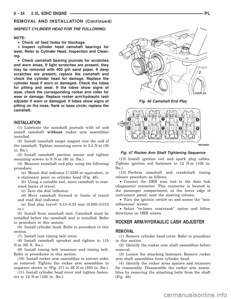
(4) Measure camshaft end play using the following
procedure:
(a) Mount dial indicator C-3339 or equivalent, to
a stationary point on cylinder head (Fig. 46).
(b) Using a suitable tool, move camshaft to rear-
ward limits of travel.
(c) Zero the dial indicator.
(d) Move camshaft forward to limits of travel
and read dial indicator.
(e) End play travel: 0.13±0.33 mm (0.005±0.013
in.).
(5) Install front camshaft seal. Camshaft must be
installed before the camshaft seal is installed. Refer
to procedure in this section.
(6) Install cylinder head. Refer to procedure in this
section.
(7) Install rear timing belt cover.
(8) Install camshaft sprocket and tighten to 115
N´m (85 ft. lbs.).
(9) Install timing belt tensioner and timing belt.
Refer to procedures in this section.
(10) Install rocker arm assemblies in correct order
as removed. Tighten the rocker arm assemblies in
sequence shown in (Fig. 47) to 28 N´m (250 in. lbs.).
(11) Install cylinder head cover and tighten fasten-
ers to 12 N´m (105 in. lbs.).(12) Install ignition coil and spark plug cables.
Tighten ignition coil fasteners to 12 N´m (105 in.
lbs.).
(13) Perform camshaft and crankshaft timing
relearn procedure as follows:
²Connect the DRB scan tool to the data link
(diagnostic) connector. This connector is located in
the passenger compartment; at the lower edge of
instrument panel; near the steering column.
²Turn the ignition switch on and access the ªmis-
cellaneousº screen.
²Select ªre-learn cam/crankº option and follow
directions on DRB screen.
ROCKER ARM/HYDRAULIC LASH ADJUSTER
REMOVAL
(1) Remove cylinder head cover. Refer to procedure
in this section.
(2) Identify the rocker arm shaft assemblies before
removal.
(3) Loosen the attaching fasteners. Remove rocker
arm shaft assemblies from cylinder head.
(4) Identify the rocker arms spacers and retainers
for reassembly. Disassemble the rocker arm assem-
blies by removing the attaching bolts from the shaft
(Fig. 48).
Fig. 46 Camshaft End Play
Fig. 47 Rocker Arm Shaft Tightening Sequence
9 - 34 2.0L SOHC ENGINEPL
REMOVAL AND INSTALLATION (Continued)
Page 760 of 1285
CYLINDER HEAD
REMOVAL
(1) Perform fuel system pressure release procedure
before attempting any repairs.Refer to Group 14,
Fuel System
(2) Disconnect negative battery cable.
(3) Remove power steering/air conditioning drive
belt. Refer to Group 7, Cooling System Accessory
Drive for procedure.
(4) Raise vehicle.
(5) Drain cooling system. Refer to Group 7, Cooling
System.
(6) Remove exhaust pipe from manifold.
(7) Remove right front wheel.
(8) Remove right side splash shield.
(9) Remove generator belt. Refer to Group 7, Cool-
ing System Accessory Drive Belts for procedure.
(10) Remove crankshaft damper. Refer to proce-
dure in this section.
(11) Remove lower torque strut.
(12) Lower vehicle and remove upper torque strut.
(13) Remove ground strap and power steering hose
support clip from engine mount bracket.
(14) Remove power steering pump assembly and
set aside.
(15) Support engine from beneath with a suitable
jack.
(16) Remove right side engine mount to bracket
through bolt.
(17) Remove the lower engine mount bracket bolt.
Raise engine slightly and remove the upper engine
mount bracket bolts.(18) Remove engine mount bracket. This procedure
may require additional raising/lowering of engine
until bracket will clear engine components.
(19) Remove front timing belt cover.
(20) Rotate engine until timing marks are aligned.
(21) Remove timing belt and tensioner. Refer to
procedures in this section.
(22) Remove camshaft sprocket. Refer to proce-
dures in this section.
(23) Remove rear timing belt cover.
(24) Disconnect fuel line at fuel rail.
(25) Remove coolant recovery container.
(26) Remove ground wire to cylinder head.
(27) Remove upper radiator hose.
(28) Remove intake manifold. Refer to procedure
in this section.
(29) Disconnect ignition coil electrical connector.
Remove coil pack and spark plug cables from engine.
(30) Remove Crankcase Closed Ventilation (CCV)
hose from cylinder head cover.
(31) Disconnect cam sensor and coolant tempera-
ture electrical connectors.
(32) Remove heater tube to cylinder head attach-
ing fasteners.
(33) Remove heater hose from thermostat housing
connector.
(34) Remove cylinder head cover.
(35) Remove cylinder head bolts.
(36) Remove cylinder head and gasket (Fig. 55).
PL2.0L SOHC ENGINE 9 - 37
REMOVAL AND INSTALLATION (Continued)
Page 763 of 1285

(13) Install ignition coil and spark plug cables.
Connect coil electrical connector.
(14) Install intake manifold. Refer to procedure in
this section.
(15) Install upper radiator hose.
(16) Install ground wire to cylinder head.
(17) Install coolant recovery container.
(18) Connect fuel line to fuel rail.
(19) Install rear timing belt cover, camshaft
sprocket, and timing belt tensioner and timing belt.
Refer to procedures in this section.
(20) Install front timing belt cover.
(21) Install engine mount bracket.
(22) Position engine and install right side engine
mount to engine mount bracket bolt. Tighten bolt to
118 N´m (87 ft. lbs.). Remove jack from beneath
engine.
(23) Install power steering pump assembly.
(24) Install power steering hose support clip and
ground strap to engine mount bracket.
(25) Install upper torque strut.
(26) Raise vehicle.
(27) Install lower torque strut.
(28) Install crankshaft damper.
(29) Install accessory drive belts. Refer to Group 7,
Cooling System Accessory Drive Belt for procedure.
(30) Install right side splash shield and front
wheel.
(31) Install exhaust pipe to exhaust manifold
flange.
(32) Lower vehicle and fill cooling system. Refer to
Group 7, Cooling System for procedure.
(33) Connect negative cable to battery.
(34) Perform camshaft and crankshaft timing
relearn procedure as follows:
²Connect the DRB scan tool to the data link
(diagnostic) connector. This connector is located in
the passenger compartment; at the lower edge of
instrument panel; near the steering column.
²Turn the ignition switch on and access the ªmis-
cellaneousº screen.
²Select ªre-learn cam/crankº option and follow
directions on DRB screen.
CRANKSHAFT DAMPER
REMOVAL
(1) Remove accessory drive belts. Refer to Group 7,
Cooling System for procedure.
(2) Raise vehicle on a hoist and remove right inner
splash shield.
(3) Remove crankshaft damper bolt. Remove
damper using the large side of Special Tool 1026 and
insert 6827-A (Fig. 61).
INSTALLATION
(1) Install crankshaft damper using M12±1.75 x
150 mm bolt, washer, thrust bearing and nut from
Special Tool 6792 (Fig. 62).
Fig. 62 Crankshaft DamperÐInstallation
1 ± M12 Ð 1.753150 MM BOLT, WASHER AND THRUST
BEARING FROM SPECIAL TOOL 6792
Fig. 60 Cylinder Head Tightening Sequence
Fig. 61 Crankshaft DamperÐRemoval
1 ± SPECIAL TOOL 6827±A INSERT
2 ± SPECIAL TOOL 1026 THREE JAW PULLER
9 - 40 2.0L SOHC ENGINEPL
REMOVAL AND INSTALLATION (Continued)
Page 769 of 1285
(10) Install right engine mount to engine mount
bracket through bolt.
(11) Remove jack from under engine.
(12) Install upper torque strut.
(13) Install power steering pump assembly.
(14) Raise vehicle and install lower torque strut.
(15) Install crankshaft damper using M12-1.75 x
150 mm bolt, washer, thrust bearing and nut from
Special Tool 6792. Install crankshaft damper bolt and
tighten to 142 N´m (100 ft. lbs.) (Fig. 77).
(16) Install accessory drive belts. Refer to Group 7,
Cooling System for procedures.
(17) Install right inner splash shield.
(18) Lower vehicle and perform camshaft and
crankshaft timing relearn procedure as follows:
²Connect the DRB scan tool to the data link
(diagnostic) connector. This connector is located in
the passenger compartment; at the lower edge of
instrument panel; near the steering column.
²Turn the ignition switch on and access the ªmis-
cellaneousº screen.
²Select ªre-learn cam/crankº option and follow
directions on DRB screen.
TIMING BELT TENSIONER
REMOVAL
(1) Remove timing belt. Refer to procedure in this
section.
(2) Remove tensioner assembly attaching bolts
(Fig. 78).
(3) Remove tensioner assembly.
CAUTION: The timing belt tensioner is serviced as
an assembly. To prevent premature timing belt fail-
ure, DO NOT separate the tensioner pulley from
mounting bracket.
INSTALLATION
(1) Install timing belt tensioner assembly. Tighten
attaching bolts to 31 N´m (275 in. lbs.).
(2) Install timing belt. Refer to procedure in this
section.
CAMSHAFT OIL SEAL
REMOVAL
CAUTION: Do Not Rotate the camshaft or crank-
shaft when timing belt is removed damage to the
engine may occur.
(1) Remove crankshaft damper, front timing belt
cover, timing belt and tensioner assembly. Refer to
procedures in this section.
(2) Hold camshaft sprocket with Special Tools
C-4687 and modified C-4687-1 as shown in (Fig. 79),
while removing attaching bolt.
(3) Remove sprocket from camshaft.
(4) Remove rear timing belt cover.
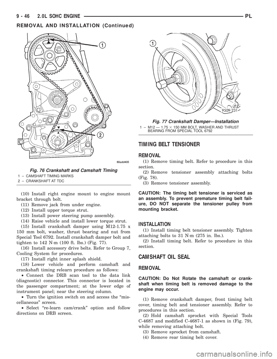
Fig. 76 Crankshaft and Camshaft Timing
1 ± CAMSHAFT TIMING MARKS
2 ± CRANKSHAFT AT TDC
Fig. 77 Crankshaft DamperÐInstallation
1 ± M12 Ð 1.753150 MM BOLT, WASHER AND THRUST
BEARING FROM SPECIAL TOOL 6792
9 - 46 2.0L SOHC ENGINEPL
REMOVAL AND INSTALLATION (Continued)
Page 778 of 1285
(17) Install rear timing belt cover and camshaft
sprocket.
(18) Install crankshaft sprocket, timing belt ten-
sioner, timing belt, and cover.
(19) Install front engine mount bracket.
(20) Remove engine from repair stand and position
on Special Tools 6135 and 6710 Engine Dolly and
Cradle. Install safety straps around the engine to
cradle and tighten and lock them into position.
(21) Install crankshaft rear oil seal. Refer to proce-
dure in this section.
(22) Install drive plate/flywheel. Apply Mopart
Lock & Seal Adhesive to bolt threads and tighten to
95 N´m (70 ft. lbs.).
(23) Install transaxle to engine.
(24) Install structural collar. Refer to procedure in
this section.
(25) Install engine assembly. Refer to procedure in
this section.
(26) Perform camshaft and crankshaft timing
relearn procedure as follows:
²Connect the DRB scan tool to the data link
(diagnostic) connector. This connector is located in
the passenger compartment; at the lower edge of
instrument panel; near the steering column.
²Turn the ignition switch on and access the ªmis-
cellaneousº screen.
²Select ªre-learn cam/crankº option and follow
directions on DRB screen.
OIL FILTER ADAPTER
REMOVE AND INSTALL
Ensure O-ring is in the groove on adapter. Align
roll pin into engine block and tighten assembly to 80
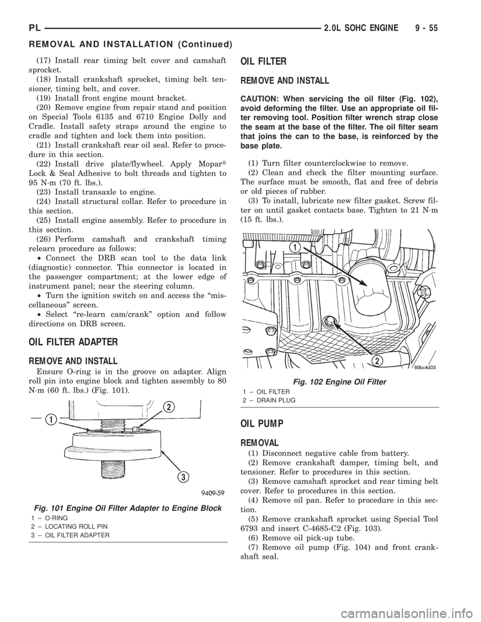
N´m (60 ft. lbs.) (Fig. 101).
OIL FILTER
REMOVE AND INSTALL
CAUTION: When servicing the oil filter (Fig. 102),
avoid deforming the filter. Use an appropriate oil fil-
ter removing tool. Position filter wrench strap close
the seam at the base of the filter. The oil filter seam
that joins the can to the base, is reinforced by the
base plate.
(1) Turn filter counterclockwise to remove.
(2) Clean and check the filter mounting surface.
The surface must be smooth, flat and free of debris
or old pieces of rubber.
(3) To install, lubricate new filter gasket. Screw fil-
ter on until gasket contacts base. Tighten to 21 N´m
(15 ft. lbs.).
OIL PUMP
REMOVAL
(1) Disconnect negative cable from battery.
(2) Remove crankshaft damper, timing belt, and
tensioner. Refer to procedures in this section.
(3) Remove camshaft sprocket and rear timing belt
cover. Refer to procedures in this section.
(4) Remove oil pan. Refer to procedure in this sec-
tion.
(5) Remove crankshaft sprocket using Special Tool
6793 and insert C-4685-C2 (Fig. 103).
(6) Remove oil pick-up tube.
(7) Remove oil pump (Fig. 104) and front crank-
shaft seal.
Fig. 101 Engine Oil Filter Adapter to Engine Block
1 ± O-RING
2 ± LOCATING ROLL PIN
3 ± OIL FILTER ADAPTER
Fig. 102 Engine Oil Filter
1 ± OIL FILTER
2 ± DRAIN PLUG
PL2.0L SOHC ENGINE 9 - 55
REMOVAL AND INSTALLATION (Continued)
Page 801 of 1285
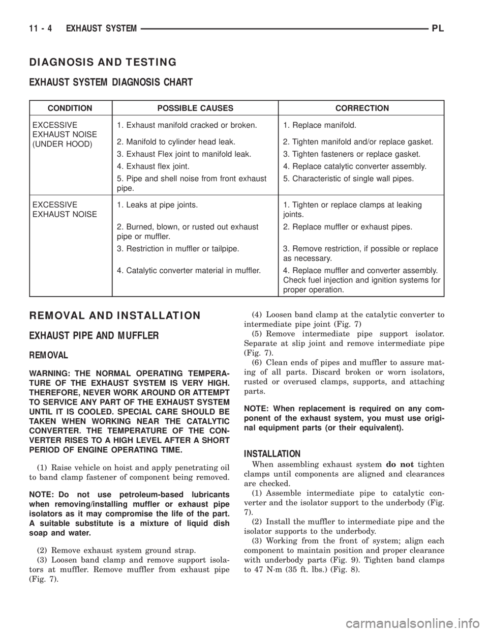
DIAGNOSIS AND TESTING
EXHAUST SYSTEM DIAGNOSIS CHART
CONDITION POSSIBLE CAUSES CORRECTION
EXCESSIVE
EXHAUST NOISE
(UNDER HOOD)1. Exhaust manifold cracked or broken. 1. Replace manifold.
2. Manifold to cylinder head leak. 2. Tighten manifold and/or replace gasket.
3. Exhaust Flex joint to manifold leak. 3. Tighten fasteners or replace gasket.
4. Exhaust flex joint. 4. Replace catalytic converter assembly.
5. Pipe and shell noise from front exhaust
pipe.5. Characteristic of single wall pipes.
EXCESSIVE
EXHAUST NOISE1. Leaks at pipe joints. 1. Tighten or replace clamps at leaking
joints.
2. Burned, blown, or rusted out exhaust
pipe or muffler.2. Replace muffler or exhaust pipes.
3. Restriction in muffler or tailpipe. 3. Remove restriction, if possible or replace
as necessary.
4. Catalytic converter material in muffler. 4. Replace muffler and converter assembly.
Check fuel injection and ignition systems for
proper operation.
REMOVAL AND INSTALLATION
EXHAUST PIPE AND MUFFLER
REMOVAL
WARNING: THE NORMAL OPERATING TEMPERA-
TURE OF THE EXHAUST SYSTEM IS VERY HIGH.
THEREFORE, NEVER WORK AROUND OR ATTEMPT
TO SERVICE ANY PART OF THE EXHAUST SYSTEM
UNTIL IT IS COOLED. SPECIAL CARE SHOULD BE
TAKEN WHEN WORKING NEAR THE CATALYTIC
CONVERTER. THE TEMPERATURE OF THE CON-
VERTER RISES TO A HIGH LEVEL AFTER A SHORT
PERIOD OF ENGINE OPERATING TIME.
(1) Raise vehicle on hoist and apply penetrating oil
to band clamp fastener of component being removed.
NOTE: Do not use petroleum-based lubricants
when removing/installing muffler or exhaust pipe
isolators as it may compromise the life of the part.
A suitable substitute is a mixture of liquid dish
soap and water.
(2) Remove exhaust system ground strap.
(3) Loosen band clamp and remove support isola-
tors at muffler. Remove muffler from exhaust pipe
(Fig. 7).(4) Loosen band clamp at the catalytic converter to
intermediate pipe joint (Fig. 7)
(5) Remove intermediate pipe support isolator.
Separate at slip joint and remove intermediate pipe
(Fig. 7).
(6) Clean ends of pipes and muffler to assure mat-
ing of all parts. Discard broken or worn isolators,
rusted or overused clamps, supports, and attaching
parts.
NOTE: When replacement is required on any com-
ponent of the exhaust system, you must use origi-
nal equipment parts (or their equivalent).
INSTALLATION
When assembling exhaust systemdo nottighten
clamps until components are aligned and clearances
are checked.
(1) Assemble intermediate pipe to catalytic con-
verter and the isolator support to the underbody (Fig.
7).
(2) Install the muffler to intermediate pipe and the
isolator supports to the underbody.
(3) Working from the front of system; align each
component to maintain position and proper clearance
with underbody parts (Fig. 9). Tighten band clamps
to 47 N´m (35 ft. lbs.) (Fig. 8).
11 - 4 EXHAUST SYSTEMPL