Page 654 of 1285
CAV CIRCUIT FUNCTION
1
Z1 18BK GROUND
2
L7 18BK/YL HEADLAMP SWITCH OUTPUT
3 L62 18BR/RD RIGHT TURN SIGNAL
RIGHT TAIL/STOP/
TURN SIGNAL LAMP
SEAT BELT SWITCH
1 2
BLACK
SEAT BELT SWITCH SENSE 20LG/RD G10 1
GROUND 18BK Z1 2
FUNCTION CIRCUIT CAV
(EXCEPT BUILT-UP-EXPORT)
M1 20PKFUSED B(+) GROUND
Z1 18BK X5 20WT/RDDISPLAY BACKLIGHT
4
1
SIREN
DISPLAY BACKLIGHT
X5 20WT/RDFUNCTION
CAV CIRCUIT
1
2
4 3
MODULE IMMOBILIZER
- -- -
FUSED B(+)
M1 20PKGROUND
Z2 20BK/LGFUSED IGNITION SWITCH OUTPUT (ST-RUN)
G5 20DB/WTPCI BUS D25 22VT/YL1
6
SENTRY KEY
FUNCTION
CAV CIRCUIT
1
2
4 3
6 5
RIGHT TAIL/STOP
LAMP
(BUILT-UP-EXPORT)
1 3
HEADLAMP SWITCH OUTPUTGROUND Z1 18BK
3
CAV CIRCUIT FUNCTION
1
L50 18WT/TN BRAKE LAMP SWITCH OUTPUT 2 L7 18BK/YL
(BUILT-UP-EXPORT)
31
BLACK
BLACK
BLACK
PL8W-80 CONNECTOR PIN-OUTS 8W - 80 - 45
PLI08045008W-10
Page 655 of 1285
1 F10 16YL/RD FUSED IGNITION SWITCH OUTPUT (RUN-ACC)
SWITCH SUNROOF
POWER SUNROOF VENT Q43 18WT/RD 2
GROUND Z3 18BK/OR 3
FUNCTION CIRCUIT CAV
CAV CIRCUIT FUNCTION
3 Q5 18WT SUNROOF MOTOR B(+)
1 Q6 18DB SUNROOF MOTOR B(-)
SUNROOF
MOTOR
CIRCUIT CAV FUNCTION
A
Q5 18WT SUNROOF MOTOR B(+)
BQ6 18DB SUNROOF MOTOR B(-)
Z3 18BK/OR GROUND
F10 18YL/RD FUSED IGNITION SWITCH OUTPUT (RUN-ACC)
Z3 18BK/OR GROUND
Q43 18WT/RD POWER SUNROOF VENT
Q46 18OR POWER SUNROOF LIMIT SWITCH D C
H G F E--
SUNROOF
CONTROL
MODULE
A H
31
BLACK
3
1
SWITCH SUNROOF VENT
-
CAV CIRCUIT FUNCTION
1 Z3 18BK/OR GROUND
2 Q46 18OR POWER SUNROOF LIMIT SWITCH
3-132
--
CAV CIRCUIT FUNCTION
1 K4 20BK/LB SENSOR GROUND
2 K22 20OR/DB THROTTLE POSITION SENSOR SIGNAL
3 K6 18VT/WT 5V SUPPLY
BLACK
31
THROTTLE POSITION
SENSOR
8W - 80 - 46 8W-80 CONNECTOR PIN-OUTSPL
008W-10PLI08046
Page 656 of 1285
Z1 20BK
2 CAV
1CIRCUIT
GROUNDFUNCTION
M1 20PK FUSED B(+)
UNDERHOOD
LAMP
CONTROL SERVOVEHICLE SPEED
41BLACK
GROUND 20BK Z1 4SPEED CONTROL BRAKE LAMP SWITCH OUTPUT 20DB/RD V30 3
SPEED CONTROL VENT SOLENOID CONTROL 20LG/RD V35 2
SPEED CONTROL VACUUM SOLENOID CONTROL 20TN/RD V36 1
FUNCTION CIRCUIT CAV
21
3 Z1 20BK GROUND
4 E2 22OR PANEL LAMPS DRIVER 4
1
SWITCH TRACTION CONTROL
TRACTION CONTROL SWITCH SENSE B27 20RD/YL 2- 1
FUNCTION CIRCUIT CAV
-
2
1
DECKLID SECURITY SWITCH SENSE G71 20VT/YL
GROUND
Z1 18BKFUNCTION
CAV CIRCUIT
1
2
CAV CIRCUIT FUNCTION
1- -
2 K54 18OR/BK TORQUE CONVERTER CLUTCH SOLENOID CONTROL
3 F12 18DB/WT FUSED IGNITION SWITCH OUTPUT (ST-RUN)
BLACK
1
23
TORQUE CONVERTER
CLUTCH SOLENOID
(ATX)
TRUNK KEY
CYLINDER SWITCH
BLACK
GRAY
WHITE
PL8W-80 CONNECTOR PIN-OUTS 8W - 80 - 47
PLI08047008W-10
Page 657 of 1285
CAV CIRCUIT FUNCTION
1
V10 18BR WASHER PUMP CONTROL SWITCH OUTPUT 2Z1 18BK GROUND
WINDSHIELD
WASHER PUMP
CAV CIRCUIT FUNCTION
1 K7 20OR 8V SUPPLY
2 K4 18BK/LB SENSOR GROUND
3 G7 20WT/OR VEHICLE SPEED SENSOR SIGNAL
VEHICLE SPEED
SENSOR
1 2
RED
WIPER HIGH SPEED OUTPUT
V4 16RD/YLWIPER LOW SPEED OUTPUT
V3 16BR/WTFUSED IGNITION SWITCH OUTPUT (RUN-ACC)
V6 16DBWIPER PARK SWITCH SENSE
V5 16DG/YL
51
MOTORWIPER
GROUND
Z1 16BKFUNCTION
CAV CIRCUIT
1
2
4 3
5
- FUSED IGNITION SWITCH OUTPUT (RUN-ACC)
WIPER HIGH SPEED OUTPUT
WIPER LOW SPEED OUTPUT V6 16DB
V3 16BR/WT Z2 22BK/LG V5 16DG/YL
GROUND WIPER PARK SWITCH SENSEFUNCTION- V4 16RD/YL 71
CAV CIRCUIT
1
2
4 3
7 6 5
WIPE/WASH SWITCH
V10 18BR
WASHER PUMP CONTROL SWITCH OUTPUT
BLACK
31
GRAY
BLACK
8W - 80 - 48 8W-80 CONNECTOR PIN-OUTSPL
008W-10PLI08048
Page 660 of 1285

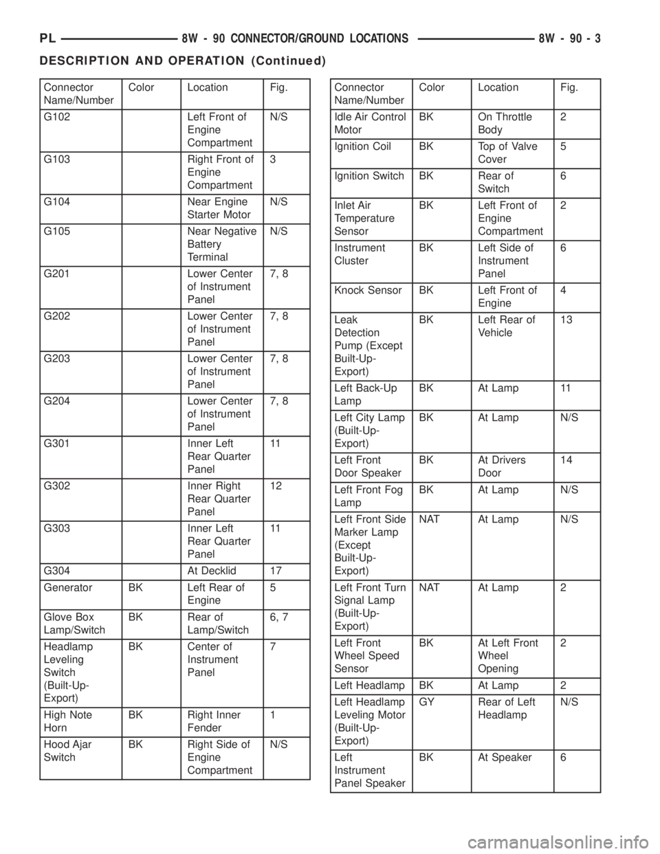
Connector
Name/NumberColor Location Fig.
G102 Left Front of
Engine
CompartmentN/S
G103 Right Front of
Engine
Compartment3
G104 Near Engine
Starter MotorN/S
G105 Near Negative
Battery
TerminalN/S
G201 Lower Center
of Instrument
Panel7, 8
G202 Lower Center
of Instrument
Panel7, 8
G203 Lower Center
of Instrument
Panel7, 8
G204 Lower Center
of Instrument
Panel7, 8
G301 Inner Left
Rear Quarter
Panel11
G302 Inner Right
Rear Quarter
Panel12
G303 Inner Left
Rear Quarter
Panel11
G304 At Decklid 17
Generator BK Left Rear of
Engine5
Glove Box
Lamp/SwitchBK Rear of
Lamp/Switch6, 7
Headlamp
Leveling
Switch
(Built-Up-
Export)BK Center of
Instrument
Panel7
High Note
HornBK Right Inner
Fender1
Hood Ajar
SwitchBK Right Side of
Engine
CompartmentN/SConnector
Name/NumberColor Location Fig.
Idle Air Control
MotorBK On Throttle
Body2
Ignition Coil BK Top of Valve
Cover5
Ignition Switch BK Rear of
Switch6
Inlet Air
Temperature
SensorBK Left Front of
Engine
Compartment2
Instrument
ClusterBK Left Side of
Instrument
Panel6
Knock Sensor BK Left Front of
Engine4
Leak
Detection
Pump (Except
Built-Up-
Export)BK Left Rear of
Vehicle13
Left Back-Up
LampBK At Lamp 11
Left City Lamp
(Built-Up-
Export)BK At Lamp N/S
Left Front
Door SpeakerBK At Drivers
Door14
Left Front Fog
LampBK At Lamp N/S
Left Front Side
Marker Lamp
(Except
Built-Up-
Export)NAT At Lamp N/S
Left Front Turn
Signal Lamp
(Built-Up-
Export)NAT At Lamp 2
Left Front
Wheel Speed
SensorBK At Left Front
Wheel
Opening2
Left Headlamp BK At Lamp 2
Left Headlamp
Leveling Motor
(Built-Up-
Export)GY Rear of Left
HeadlampN/S
Left
Instrument
Panel SpeakerBK At Speaker 6
PL8W - 90 CONNECTOR/GROUND LOCATIONS 8W - 90 - 3
DESCRIPTION AND OPERATION (Continued)
Page 680 of 1285

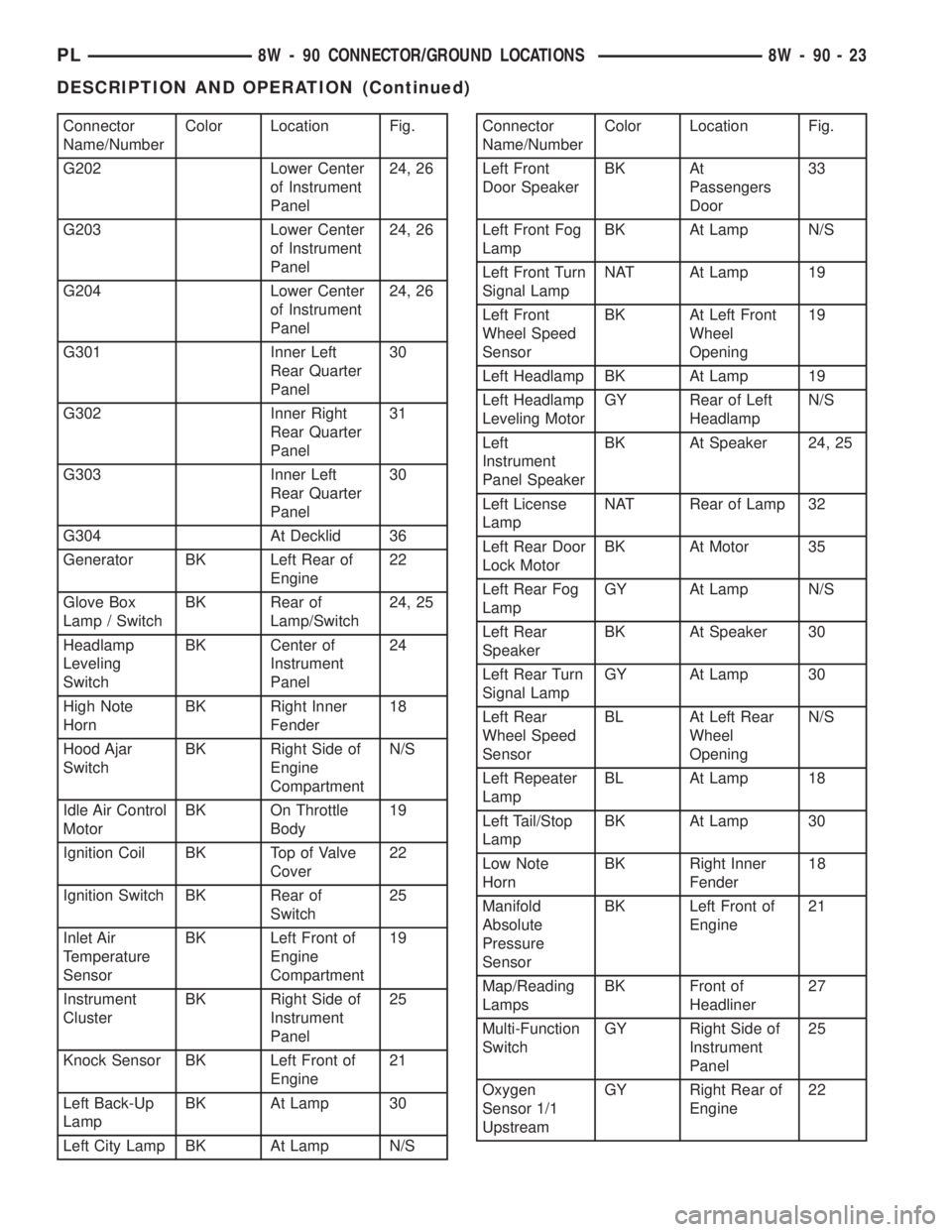
Connector
Name/NumberColor Location Fig.
G202 Lower Center
of Instrument
Panel24, 26
G203 Lower Center
of Instrument
Panel24, 26
G204 Lower Center
of Instrument
Panel24, 26
G301 Inner Left
Rear Quarter
Panel30
G302 Inner Right
Rear Quarter
Panel31
G303 Inner Left
Rear Quarter
Panel30
G304 At Decklid 36
Generator BK Left Rear of
Engine22
Glove Box
Lamp / SwitchBK Rear of
Lamp/Switch24, 25
Headlamp
Leveling
SwitchBK Center of
Instrument
Panel24
High Note
HornBK Right Inner
Fender18
Hood Ajar
SwitchBK Right Side of
Engine
CompartmentN/S
Idle Air Control
MotorBK On Throttle
Body19
Ignition Coil BK Top of Valve
Cover22
Ignition Switch BK Rear of
Switch25
Inlet Air
Temperature
SensorBK Left Front of
Engine
Compartment19
Instrument
ClusterBK Right Side of
Instrument
Panel25
Knock Sensor BK Left Front of
Engine21
Left Back-Up
LampBK At Lamp 30
Left City Lamp BK At Lamp N/SConnector
Name/NumberColor Location Fig.
Left Front
Door SpeakerBK At
Passengers
Door33
Left Front Fog
LampBK At Lamp N/S
Left Front Turn
Signal LampNAT At Lamp 19
Left Front
Wheel Speed
SensorBK At Left Front
Wheel
Opening19
Left Headlamp BK At Lamp 19
Left Headlamp
Leveling MotorGY Rear of Left
HeadlampN/S
Left
Instrument
Panel SpeakerBK At Speaker 24, 25
Left License
LampNAT Rear of Lamp 32
Left Rear Door
Lock MotorBK At Motor 35
Left Rear Fog
LampGY At Lamp N/S
Left Rear
SpeakerBK At Speaker 30
Left Rear Turn
Signal LampGY At Lamp 30
Left Rear
Wheel Speed
SensorBL At Left Rear
Wheel
OpeningN/S
Left Repeater
LampBL At Lamp 18
Left Tail/Stop
LampBK At Lamp 30
Low Note
HornBK Right Inner
Fender18
Manifold
Absolute
Pressure
SensorBK Left Front of
Engine21
Map/Reading
LampsBK Front of
Headliner27
Multi-Function
SwitchGY Right Side of
Instrument
Panel25
Oxygen
Sensor 1/1
UpstreamGY Right Rear of
Engine22
PL8W - 90 CONNECTOR/GROUND LOCATIONS 8W - 90 - 23
DESCRIPTION AND OPERATION (Continued)
Page 698 of 1285

8W-95 SPLICE LOCATIONS
DESCRIPTION AND OPERATION
INTRODUCTION
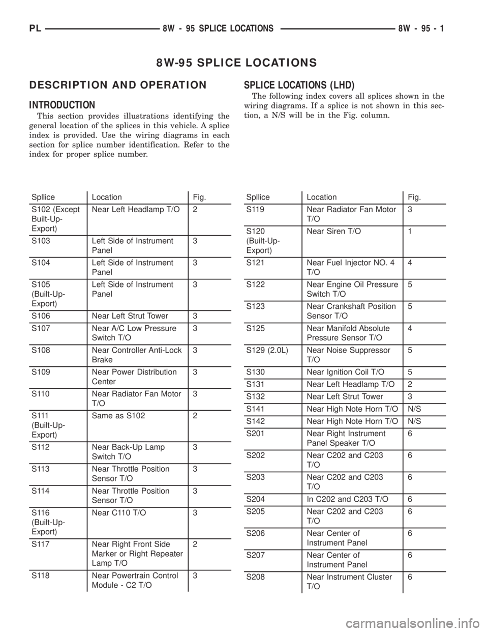
This section provides illustrations identifying the
general location of the splices in this vehicle. A splice
index is provided. Use the wiring diagrams in each
section for splice number identification. Refer to the
index for proper splice number.
SPLICE LOCATIONS (LHD)
The following index covers all splices shown in the
wiring diagrams. If a splice is not shown in this sec-
tion, a N/S will be in the Fig. column.
Spllice Location Fig.
S102 (Except
Built-Up-
Export)Near Left Headlamp T/O 2
S103 Left Side of Instrument
Panel3
S104 Left Side of Instrument
Panel3
S105
(Built-Up-
Export)Left Side of Instrument
Panel3
S106 Near Left Strut Tower 3
S107 Near A/C Low Pressure
Switch T/O3
S108 Near Controller Anti-Lock
Brake3
S109 Near Power Distribution
Center3
S110 Near Radiator Fan Motor
T/O3
S 111
(Built-Up-
Export)Same as S102 2
S112 Near Back-Up Lamp
Switch T/O3
S113 Near Throttle Position
Sensor T/O3
S114 Near Throttle Position
Sensor T/O3
S116
(Built-Up-
Export)Near C110 T/O 3
S117 Near Right Front Side
Marker or Right Repeater
Lamp T/O2
S118 Near Powertrain Control
Module - C2 T/O3Spllice Location Fig.
S119 Near Radiator Fan Motor
T/O3
S120
(Built-Up-
Export)Near Siren T/O 1
S121 Near Fuel Injector NO. 4
T/O4
S122 Near Engine Oil Pressure
Switch T/O5
S123 Near Crankshaft Position
Sensor T/O5
S125 Near Manifold Absolute
Pressure Sensor T/O4
S129 (2.0L) Near Noise Suppressor
T/O5
S130 Near Ignition Coil T/O 5
S131 Near Left Headlamp T/O 2
S132 Near Left Strut Tower 3
S141 Near High Note Horn T/O N/S
S142 Near High Note Horn T/O N/S
S201 Near Right Instrument
Panel Speaker T/O6
S202 Near C202 and C203
T/O6
S203 Near C202 and C203
T/O6
S204 In C202 and C203 T/O 6
S205 Near C202 and C203
T/O6
S206 Near Center of
Instrument Panel6
S207 Near Center of
Instrument Panel6
S208 Near Instrument Cluster
T/O6
PL8W - 95 SPLICE LOCATIONS 8W - 95 - 1
Page 710 of 1285

SPLICE LOCATIONS (RHD)
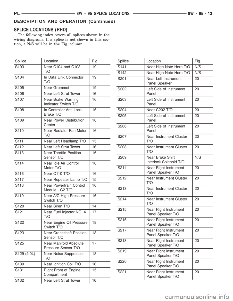
The following index covers all splices shown in the
wiring diagrams. If a splice is not shown in this sec-
tion, a N/S will be in the Fig. column.
Spllice Location Fig.
S103 Near C104 and C103
T/O19
S104 In Data Link Connector
T/O19
S105 Near Grommet 19
S106 Near Left Strut Tower 16
S107 Near Brake Warning
Indicator Switch T/O16
S108 In Controller Anti-Lock
Brake T/O16
S109 Near Power Distribution
Center16
S110 Near Radiator Fan Motor
T/O16
S111 Near Left Headlamp T/O 15
S112 Near Left Strut Tower 16
S113 Near Throttle Position
Sensor T/O16
S114 Near Idle Air Control
Motor T/O16
S116 Near C110 T/O 16
S117 Near Repeater Lamp T/O 15
S118 Near Powertrain Control
Module - C2 T/O16
S119 Near A/C High Pressure
Switch T/O16
S120 Near Siren T/O 14
S121 Near Fuel Injector NO. 4
T/O17
S122 Near Engine Oil Pressure
Switch T/O18
S123 Near Crankshaft Position
Sensor T/O18
S125 Near Manifold Absolute
Pressure Sensor T/O17
S129 (2.0L) Near Noise Suppressor
T/O18
S130 Near Ignition Coil T/O 18
S131 Right Front of Engine
Compartment15
S132 Near Left Strut Tower 16Spllice Location Fig.
S141 Near High Note Horn T/O N/S
S142 Near High Note Horn T/O N/S
S201 Near Left Instrument
Panel Speaker20
S202 Left Side of Instrument
Panel20
S203 Left Side of Instrument
Panel20
S204 Near C202 T/O 20
S205 Left Side of Instrument
Panel20
S206 Left Side of Instrument
Panel20
S207 Near Instrument Cluster
T/O20
S208 Near Instrument Cluster
T/O20
S209 Near Brake Shift
Interlock Solenoid T/ON/S
S211 Near Right Instrument
Panel Speaker T/O20
S212 Near Instrument Cluster
T/O20
S213 Near Instrument Cluster
T/O20
S214 Near Instrument Cluster
T/O20
S215 Near Right Instrument
Panel Speaker T/O20
S216 Near Right Instrument
Panel Speaker T/O20
S217 Near Right Instrument
Panel Speaker T/O20
S218 Near Right Instrument
Panel Speaker T/O20
S219 Near Right Instrument
Panel Speaker T/O20
S220 Near Right Instrument
Panel Speaker T/O20
S221 Near Right Instrument
Panel Speaker T/O20
PL8W - 95 SPLICE LOCATIONS 8W - 95 - 13
DESCRIPTION AND OPERATION (Continued)