2000 DODGE NEON motor
[x] Cancel search: motorPage 1233 of 1285
GENERAL INFORMATION
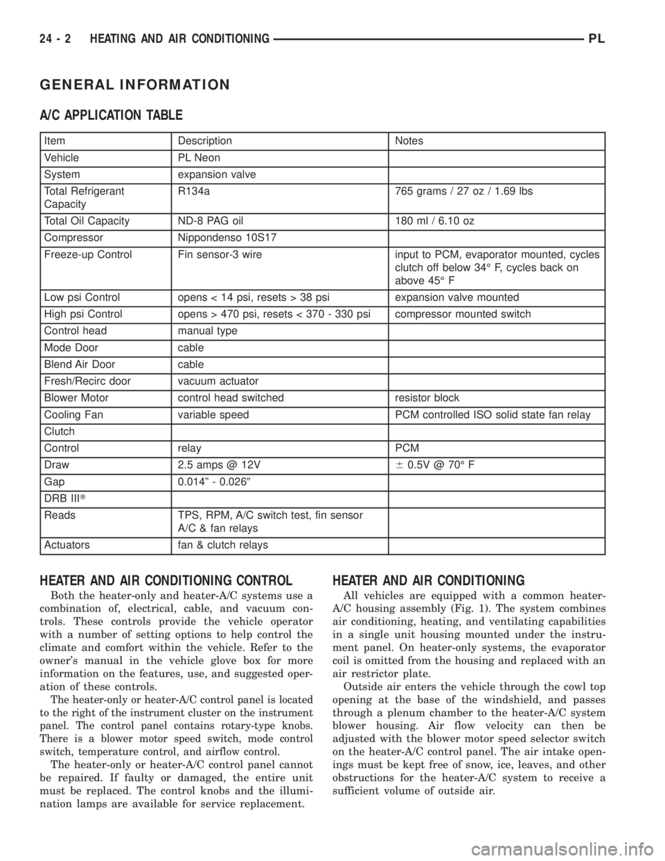
A/C APPLICATION TABLE
Item Description Notes
Vehicle PL Neon
System expansion valve
Total Refrigerant
CapacityR134a 765 grams / 27 oz / 1.69 lbs
Total Oil Capacity ND-8 PAG oil 180 ml / 6.10 oz
Compressor Nippondenso 10S17
Freeze-up Control Fin sensor-3 wire input to PCM, evaporator mounted, cycles
clutch off below 34É F, cycles back on
above 45É F
Low psi Control opens < 14 psi, resets > 38 psi expansion valve mounted
High psi Control opens > 470 psi, resets < 370 - 330 psi compressor mounted switch
Control head manual type
Mode Door cable
Blend Air Door cable
Fresh/Recirc door vacuum actuator
Blower Motor control head switched resistor block
Cooling Fan variable speed PCM controlled ISO solid state fan relay
Clutch
Control relay PCM
Draw 2.5 amps @ 12V60.5V @ 70É F
Gap 0.014º - 0.0269
DRB IIIT
Reads TPS, RPM, A/C switch test, fin sensor
A/C & fan relays
Actuators fan & clutch relays
HEATER AND AIR CONDITIONING CONTROL
Both the heater-only and heater-A/C systems use a
combination of, electrical, cable, and vacuum con-
trols. These controls provide the vehicle operator
with a number of setting options to help control the
climate and comfort within the vehicle. Refer to the
owner's manual in the vehicle glove box for more
information on the features, use, and suggested oper-
ation of these controls.
The heater-only or heater-A/C control panel is located
to the right of the instrument cluster on the instrument
panel. The control panel contains rotary-type knobs.
There is a blower motor speed switch, mode control
switch, temperature control, and airflow control.
The heater-only or heater-A/C control panel cannot
be repaired. If faulty or damaged, the entire unit
must be replaced. The control knobs and the illumi-
nation lamps are available for service replacement.
HEATER AND AIR CONDITIONING
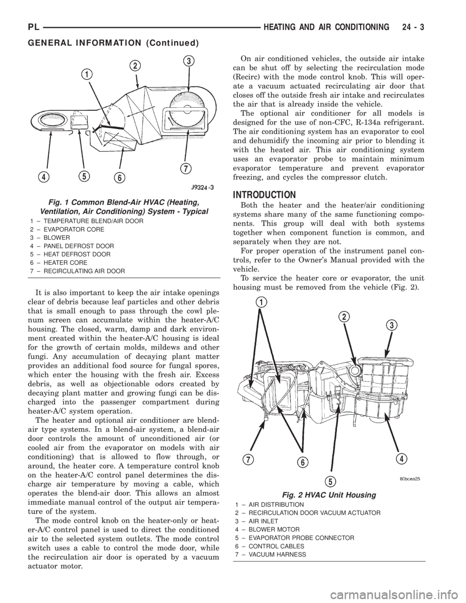
All vehicles are equipped with a common heater-
A/C housing assembly (Fig. 1). The system combines
air conditioning, heating, and ventilating capabilities
in a single unit housing mounted under the instru-
ment panel. On heater-only systems, the evaporator
coil is omitted from the housing and replaced with an
air restrictor plate.
Outside air enters the vehicle through the cowl top
opening at the base of the windshield, and passes
through a plenum chamber to the heater-A/C system
blower housing. Air flow velocity can then be
adjusted with the blower motor speed selector switch
on the heater-A/C control panel. The air intake open-
ings must be kept free of snow, ice, leaves, and other
obstructions for the heater-A/C system to receive a
sufficient volume of outside air.
24 - 2 HEATING AND AIR CONDITIONINGPL
Page 1234 of 1285
It is also important to keep the air intake openings
clear of debris because leaf particles and other debris
that is small enough to pass through the cowl ple-
num screen can accumulate within the heater-A/C
housing. The closed, warm, damp and dark environ-
ment created within the heater-A/C housing is ideal
for the growth of certain molds, mildews and other
fungi. Any accumulation of decaying plant matter
provides an additional food source for fungal spores,
which enter the housing with the fresh air. Excess
debris, as well as objectionable odors created by
decaying plant matter and growing fungi can be dis-
charged into the passenger compartment during
heater-A/C system operation.
The heater and optional air conditioner are blend-
air type systems. In a blend-air system, a blend-air
door controls the amount of unconditioned air (or
cooled air from the evaporator on models with air
conditioning) that is allowed to flow through, or
around, the heater core. A temperature control knob
on the heater-A/C control panel determines the dis-
charge air temperature by moving a cable, which
operates the blend-air door. This allows an almost
immediate manual control of the output air tempera-
ture of the system.
The mode control knob on the heater-only or heat-
er-A/C control panel is used to direct the conditioned
air to the selected system outlets. The mode control
switch uses a cable to control the mode door, while
the recirculation air door is operated by a vacuum
actuator motor.On air conditioned vehicles, the outside air intake
can be shut off by selecting the recirculation mode
(Recirc) with the mode control knob. This will oper-
ate a vacuum actuated recirculating air door that
closes off the outside fresh air intake and recirculates
the air that is already inside the vehicle.
The optional air conditioner for all models is
designed for the use of non-CFC, R-134a refrigerant.
The air conditioning system has an evaporator to cool
and dehumidify the incoming air prior to blending it
with the heated air. This air conditioning system
uses an evaporator probe to maintain minimum
evaporator temperature and prevent evaporator
freezing, and cycles the compressor clutch.
INTRODUCTION
Both the heater and the heater/air conditioning
systems share many of the same functioning compo-
nents. This group will deal with both systems
together when component function is common, and
separately when they are not.
For proper operation of the instrument panel con-
trols, refer to the Owner's Manual provided with the
vehicle.
To service the heater core or evaporator, the unit
housing must be removed from the vehicle (Fig. 2).Fig. 1 Common Blend-Air HVAC (Heating,
Ventilation, Air Conditioning) System - Typical
1 ± TEMPERATURE BLEND/AIR DOOR
2 ± EVAPORATOR CORE
3 ± BLOWER
4 ± PANEL DEFROST DOOR
5 ± HEAT DEFROST DOOR
6 ± HEATER CORE
7 ± RECIRCULATING AIR DOOR
Fig. 2 HVAC Unit Housing
1 ± AIR DISTRIBUTION
2 ± RECIRCULATION DOOR VACUUM ACTUATOR
3 ± AIR INLET
4 ± BLOWER MOTOR
5 ± EVAPORATOR PROBE CONNECTOR
6 ± CONTROL CABLES
7 ± VACUUM HARNESS
PLHEATING AND AIR CONDITIONING 24 - 3
GENERAL INFORMATION (Continued)
Page 1236 of 1285
A/C SERVICE PORT VALVE CORES
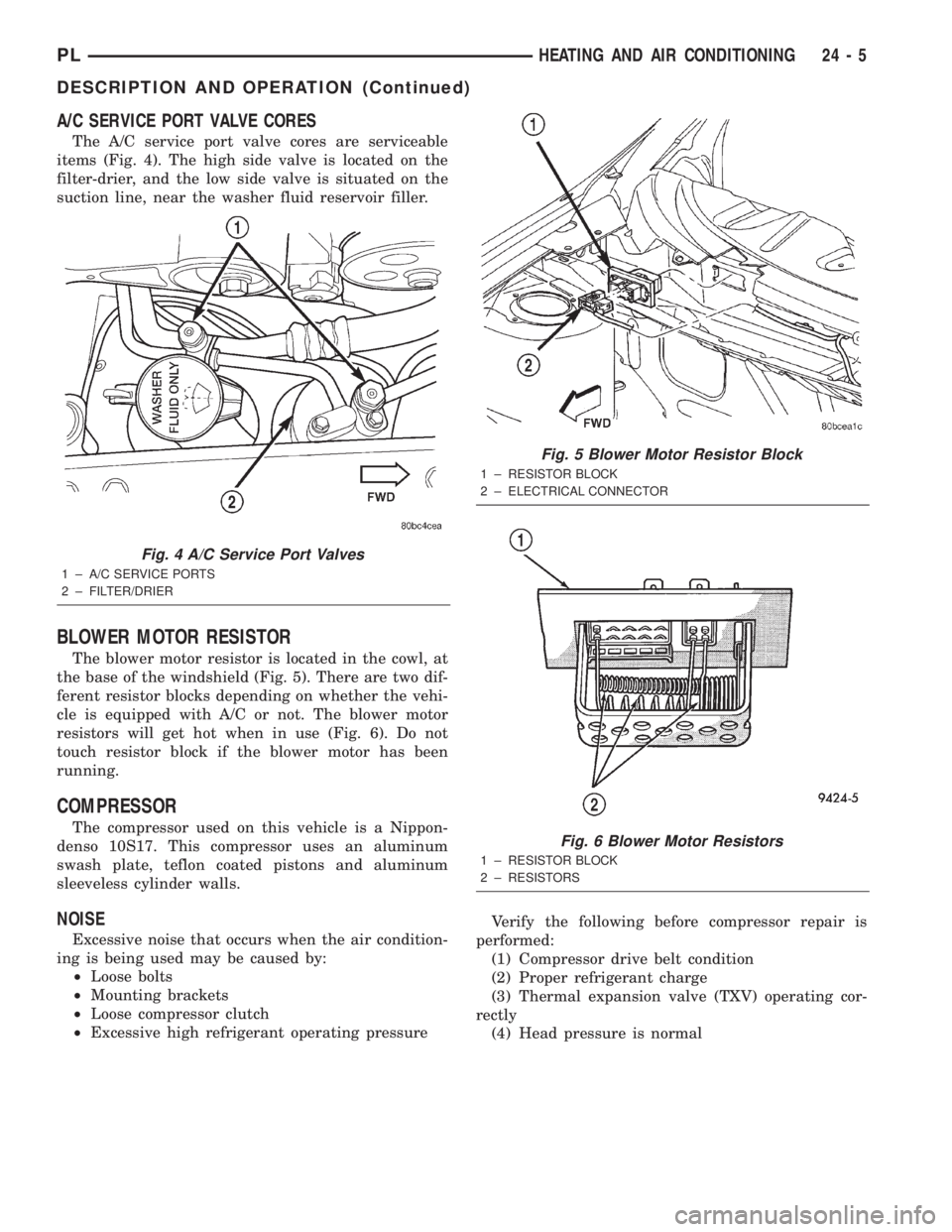
The A/C service port valve cores are serviceable
items (Fig. 4). The high side valve is located on the
filter-drier, and the low side valve is situated on the
suction line, near the washer fluid reservoir filler.
BLOWER MOTOR RESISTOR
The blower motor resistor is located in the cowl, at
the base of the windshield (Fig. 5). There are two dif-
ferent resistor blocks depending on whether the vehi-
cle is equipped with A/C or not. The blower motor
resistors will get hot when in use (Fig. 6). Do not
touch resistor block if the blower motor has been
running.
COMPRESSOR
The compressor used on this vehicle is a Nippon-
denso 10S17. This compressor uses an aluminum
swash plate, teflon coated pistons and aluminum
sleeveless cylinder walls.
NOISE
Excessive noise that occurs when the air condition-
ing is being used may be caused by:
²Loose bolts
²Mounting brackets
²Loose compressor clutch
²Excessive high refrigerant operating pressureVerify the following before compressor repair is
performed:
(1) Compressor drive belt condition
(2) Proper refrigerant charge
(3) Thermal expansion valve (TXV) operating cor-
rectly
(4) Head pressure is normal
Fig. 4 A/C Service Port Valves
1 ± A/C SERVICE PORTS
2 ± FILTER/DRIER
Fig. 5 Blower Motor Resistor Block
1 ± RESISTOR BLOCK
2 ± ELECTRICAL CONNECTOR
Fig. 6 Blower Motor Resistors
1 ± RESISTOR BLOCK
2 ± RESISTORS
PLHEATING AND AIR CONDITIONING 24 - 5
DESCRIPTION AND OPERATION (Continued)
Page 1239 of 1285
NOTE: The oil used in the compressor is ND8 PAG
R-134a refrigerant oil. Only refrigerant oil of the
same type should be used to service the system.
Do not use any other oil. The oil container should
be kept tightly capped until it is ready for use.
Tightly cap afterwards to prevent contamination
from dirt and moisture. Refrigerant oil will quickly
absorb any moisture it comes in contact with. Spe-
cial effort must be used to keep all R-134a system
components moisture-free. Moisture in the oil is
very difficult to remove and will cause a reliability
problem with the compressor.
It will not be necessary to check oil level in the
compressor or to add oil unless there has been an oil
loss. Oil loss at a leak point will be evident by the
presence of a wet, shiny surface around the leak.
REFRIGERANT OIL LEVEL CHECK
When an air conditioning system is first assem-
bled, all components (except the compressor) are
refrigerant oil free. After the system has been
charged with R-134a refrigerant and operated, the oil
in the compressor is dispersed through the lines and
components. The evaporator, condenser, and filter-
drier will retain a significant amount of oil, refer to
the Refrigerant Oil Capacities chart. When a compo-
nent is replaced, the specified amount of refrigerant
oil must be added. When the compressor is replaced,
the amount of oil that is retained in the rest of the
system must be drained from the replacement com-
pressor. When a line or component has ruptured and
oil has escaped, the compressor should be removed
and drained. The filter-drier must be replaced along
with the ruptured part. The oil capacity of the sys-
tem, minus the amount of oil still in the remaining
components, can be measured and poured into the
suction port of the compressor.
VACUUM CONTROL SYSTEM
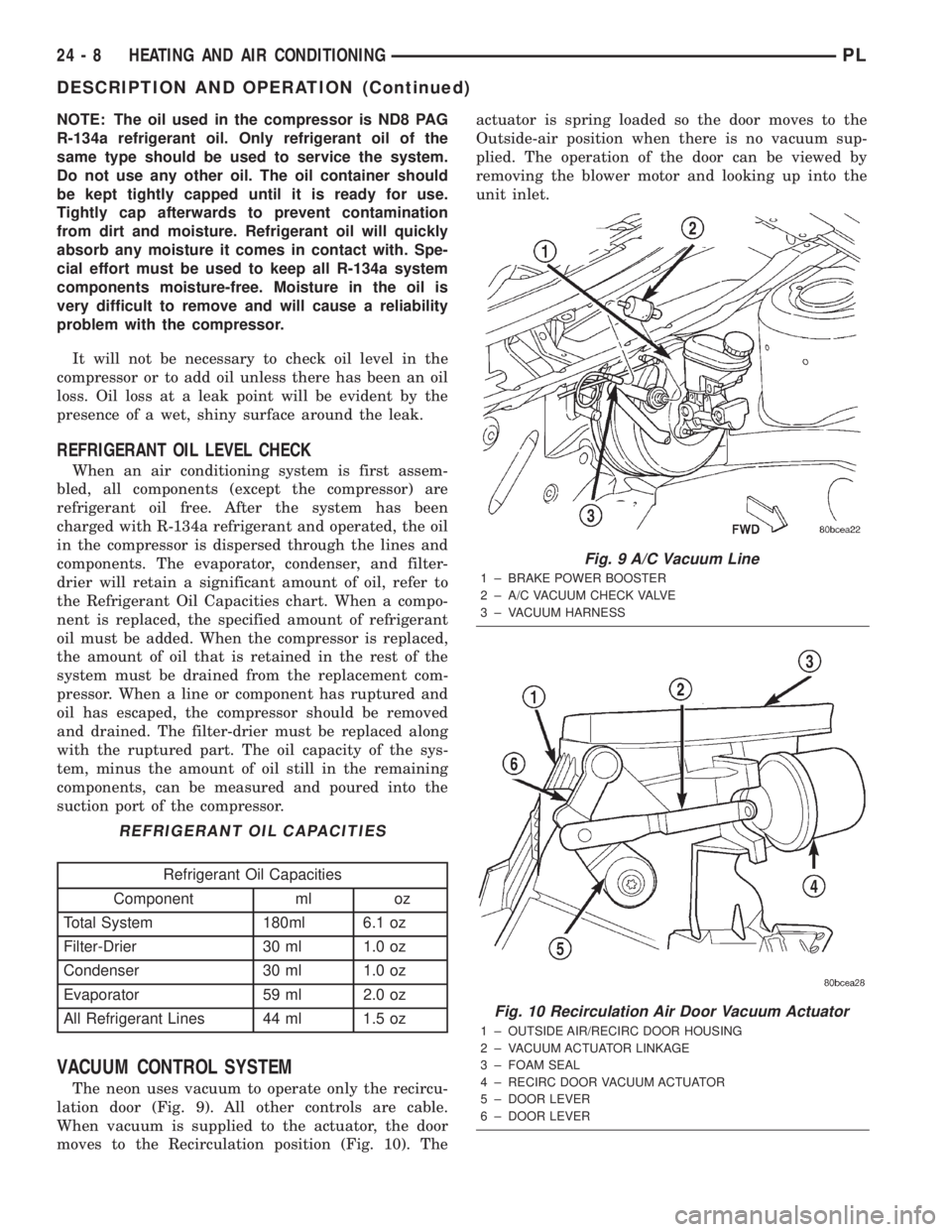
The neon uses vacuum to operate only the recircu-
lation door (Fig. 9). All other controls are cable.
When vacuum is supplied to the actuator, the door
moves to the Recirculation position (Fig. 10). Theactuator is spring loaded so the door moves to the
Outside-air position when there is no vacuum sup-
plied. The operation of the door can be viewed by
removing the blower motor and looking up into the
unit inlet.
REFRIGERANT OIL CAPACITIES
Refrigerant Oil Capacities
Component ml oz
Total System 180ml 6.1 oz
Filter-Drier 30 ml 1.0 oz
Condenser 30 ml 1.0 oz
Evaporator 59 ml 2.0 oz
All Refrigerant Lines 44 ml 1.5 oz
Fig. 9 A/C Vacuum Line
1 ± BRAKE POWER BOOSTER
2 ± A/C VACUUM CHECK VALVE
3 ± VACUUM HARNESS
Fig. 10 Recirculation Air Door Vacuum Actuator
1 ± OUTSIDE AIR/RECIRC DOOR HOUSING
2 ± VACUUM ACTUATOR LINKAGE
3 ± FOAM SEAL
4 ± RECIRC DOOR VACUUM ACTUATOR
5 ± DOOR LEVER
6 ± DOOR LEVER
24 - 8 HEATING AND AIR CONDITIONINGPL
DESCRIPTION AND OPERATION (Continued)
Page 1240 of 1285
Normally, vacuum is supplied to the actuator by
placing the Circulation control knob in the Recircula-
tion position. The Mode and the circulation control
are mechanically interlocked so the circulation con-
trol cannot be placed in the RECIRC position if the
mode control is at or between the mix and defrost
positions. Vacuum is supplied to the actuator only
when circulation control is at the RECIRC position.
If the circulation control is between the outside air
position and RECIRC position the system will be in
outside air. If the circulation control is in the
RECIRC position and the mode control is moved from
the floor to the defrost positions, the circulation con-
trol will move from the RECIRC position, to the out-
side air position beginning at the mix position. This
is to prevent window fogging.
DIAGNOSIS AND TESTING
A/C PERFORMANCE TEST
The air conditioning system is designed to remove
heat and humidity from the air entering the passen-
ger compartment. The evaporator, located in the
heater A/C unit, is cooled to temperatures near the
freezing point. As warm damp air passes over the
fins in the evaporator, moisture in the air condenses
to water, dehumidifying the air. Condensation on the
evaporator fins reduces the evaporators ability to
absorb heat. During periods of high heat and humid-
ity, an air conditioning system will be less effective.
With the instrument control set to RECIRC, only air
from the passenger compartment passes through theevaporator. As the passenger compartment air dehu-
midifies, A/C performance levels rise.
PERFORMANCE TEST PROCEDURE
Review Safety Precautions and Warnings in this
group before proceeding with this procedure. Air tem-
perature in test room and on vehicle must be 21É C
(70ÉF) minimum for this test.
NOTE: When connecting the service equipment
coupling to the line fitting, verify that the valve of
the coupling is fully closed. This will reduce the
amount of effort required to make the connection.
(1) Connect a tachometer and manifold gauge set.
(2) Set control to A/C, RECIRC, and PANEL, tem-
perature lever on full cool and blower on high.
(3) Start engine and hold at 1000 rpm with A/C
clutch engaged.
(4) Engine should be warmed up with doors and
windows closed.
(5) Insert a thermometer in the left center A/C
outlet and operate the engine for five minutes. The
A/C clutch may cycle depending on ambient condi-
tions.
(6) With the A/C clutch engaged, compare the dis-
charge air temperature to the A/C Performance Tem-
peratures chart.
(7) If the discharge air temperature fails to meet
the specifications in the performance temperature
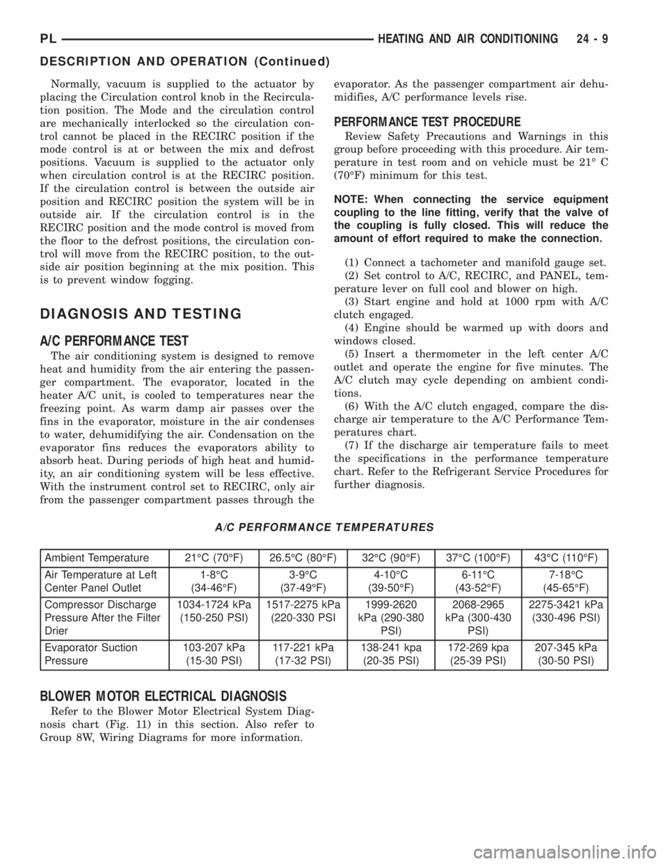
chart. Refer to the Refrigerant Service Procedures for
further diagnosis.
A/C PERFORMANCE TEMPERATURES
Ambient Temperature 21ÉC (70ÉF) 26.5ÉC (80ÉF) 32ÉC (90ÉF) 37ÉC (100ÉF) 43ÉC (110ÉF)
Air Temperature at Left
Center Panel Outlet1-8ÉC
(34-46ÉF)3-9ÉC
(37-49ÉF)4-10ÉC
(39-50ÉF)6-11ÉC
(43-52ÉF)7-18ÉC
(45-65ÉF)
Compressor Discharge
Pressure After the Filter
Drier1034-1724 kPa
(150-250 PSI)1517-2275 kPa
(220-330 PSI1999-2620
kPa (290-380
PSI)2068-2965
kPa (300-430
PSI)2275-3421 kPa
(330-496 PSI)
Evaporator Suction
Pressure103-207 kPa
(15-30 PSI)117-221 kPa
(17-32 PSI)138-241 kpa
(20-35 PSI)172-269 kpa
(25-39 PSI)207-345 kPa
(30-50 PSI)
BLOWER MOTOR ELECTRICAL DIAGNOSIS
Refer to the Blower Motor Electrical System Diag-
nosis chart (Fig. 11) in this section. Also refer to
Group 8W, Wiring Diagrams for more information.
PLHEATING AND AIR CONDITIONING 24 - 9
DESCRIPTION AND OPERATION (Continued)
Page 1241 of 1285
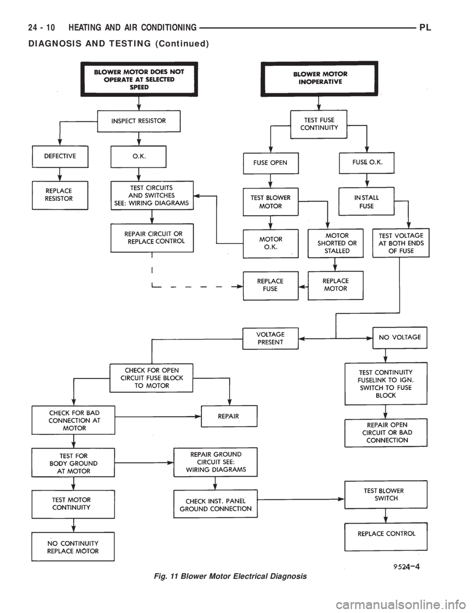
Fig. 11 Blower Motor Electrical Diagnosis
24 - 10 HEATING AND AIR CONDITIONINGPL
DIAGNOSIS AND TESTING (Continued)
Page 1242 of 1285
BLOWER MOTOR VIBRATION AND/OR NOISE
DIAGNOSIS
The resistor block supplies the blower motor with
varied voltage (low and middle speeds) or battery
voltage (high speed).
CAUTION: Stay clear of the blower motor and resis-
tor block (Hot). Do not operate the blower motor
with the resistor block removed from the heater-A/C
housing.
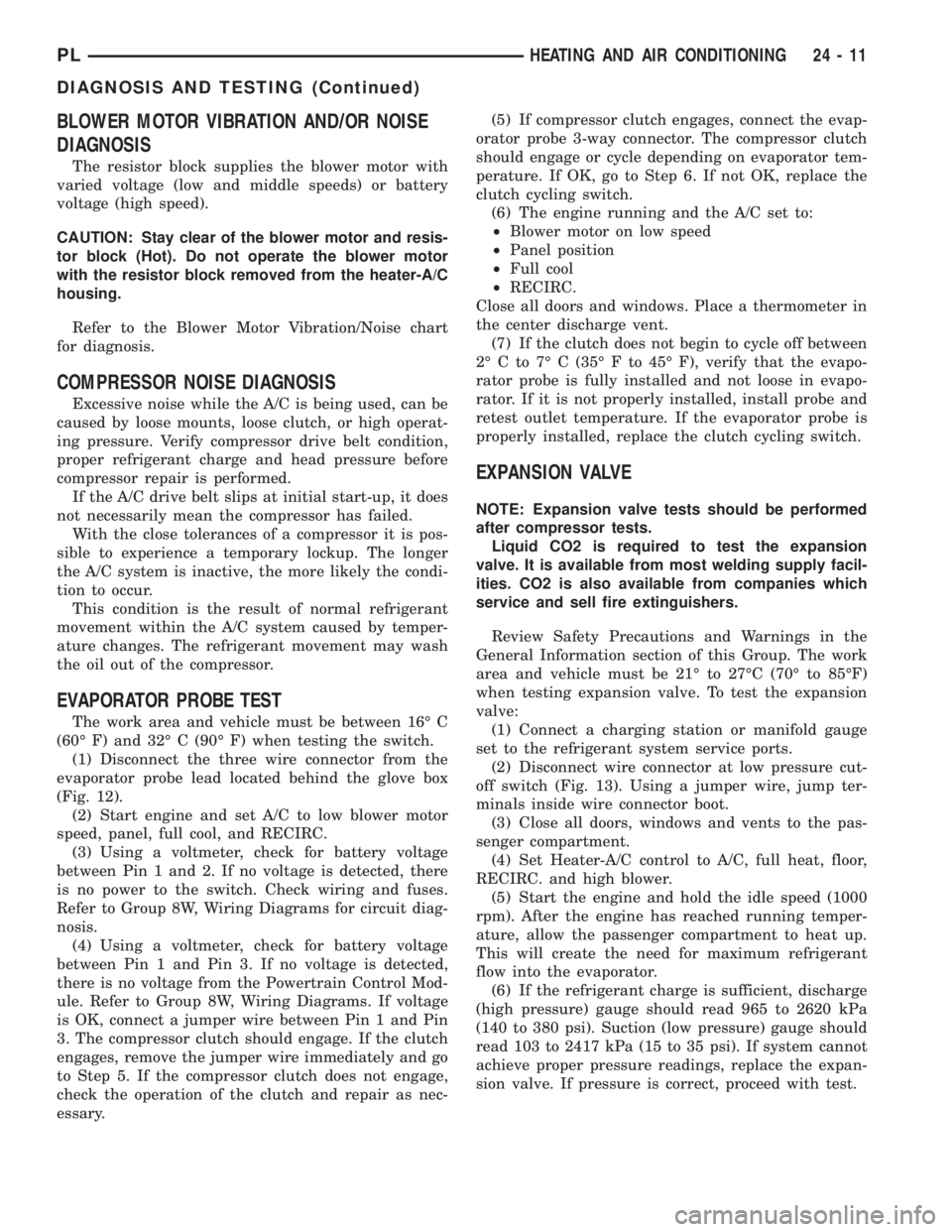
Refer to the Blower Motor Vibration/Noise chart
for diagnosis.
COMPRESSOR NOISE DIAGNOSIS
Excessive noise while the A/C is being used, can be
caused by loose mounts, loose clutch, or high operat-
ing pressure. Verify compressor drive belt condition,
proper refrigerant charge and head pressure before
compressor repair is performed.
If the A/C drive belt slips at initial start-up, it does
not necessarily mean the compressor has failed.
With the close tolerances of a compressor it is pos-
sible to experience a temporary lockup. The longer
the A/C system is inactive, the more likely the condi-
tion to occur.
This condition is the result of normal refrigerant
movement within the A/C system caused by temper-
ature changes. The refrigerant movement may wash
the oil out of the compressor.
EVAPORATOR PROBE TEST
The work area and vehicle must be between 16É C
(60É F) and 32É C (90É F) when testing the switch.
(1) Disconnect the three wire connector from the
evaporator probe lead located behind the glove box
(Fig. 12).
(2) Start engine and set A/C to low blower motor
speed, panel, full cool, and RECIRC.
(3) Using a voltmeter, check for battery voltage
between Pin 1 and 2. If no voltage is detected, there
is no power to the switch. Check wiring and fuses.
Refer to Group 8W, Wiring Diagrams for circuit diag-
nosis.
(4) Using a voltmeter, check for battery voltage
between Pin 1 and Pin 3. If no voltage is detected,
there is no voltage from the Powertrain Control Mod-
ule. Refer to Group 8W, Wiring Diagrams. If voltage
is OK, connect a jumper wire between Pin 1 and Pin
3. The compressor clutch should engage. If the clutch
engages, remove the jumper wire immediately and go
to Step 5. If the compressor clutch does not engage,
check the operation of the clutch and repair as nec-
essary.(5) If compressor clutch engages, connect the evap-
orator probe 3-way connector. The compressor clutch
should engage or cycle depending on evaporator tem-
perature. If OK, go to Step 6. If not OK, replace the
clutch cycling switch.
(6) The engine running and the A/C set to:
²Blower motor on low speed
²Panel position
²Full cool
²RECIRC.
Close all doors and windows. Place a thermometer in
the center discharge vent.
(7) If the clutch does not begin to cycle off between
2É C to 7É C (35É F to 45É F), verify that the evapo-
rator probe is fully installed and not loose in evapo-
rator. If it is not properly installed, install probe and
retest outlet temperature. If the evaporator probe is
properly installed, replace the clutch cycling switch.
EXPANSION VALVE
NOTE: Expansion valve tests should be performed
after compressor tests.
Liquid CO2 is required to test the expansion
valve. It is available from most welding supply facil-
ities. CO2 is also available from companies which
service and sell fire extinguishers.
Review Safety Precautions and Warnings in the
General Information section of this Group. The work
area and vehicle must be 21É to 27ÉC (70É to 85ÉF)
when testing expansion valve. To test the expansion
valve:
(1) Connect a charging station or manifold gauge
set to the refrigerant system service ports.
(2) Disconnect wire connector at low pressure cut-
off switch (Fig. 13). Using a jumper wire, jump ter-
minals inside wire connector boot.
(3) Close all doors, windows and vents to the pas-
senger compartment.
(4) Set Heater-A/C control to A/C, full heat, floor,
RECIRC. and high blower.
(5) Start the engine and hold the idle speed (1000
rpm). After the engine has reached running temper-
ature, allow the passenger compartment to heat up.
This will create the need for maximum refrigerant
flow into the evaporator.
(6) If the refrigerant charge is sufficient, discharge
(high pressure) gauge should read 965 to 2620 kPa
(140 to 380 psi). Suction (low pressure) gauge should
read 103 to 2417 kPa (15 to 35 psi). If system cannot
achieve proper pressure readings, replace the expan-
sion valve. If pressure is correct, proceed with test.
PLHEATING AND AIR CONDITIONING 24 - 11
DIAGNOSIS AND TESTING (Continued)
Page 1243 of 1285
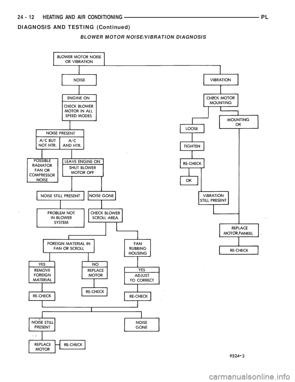
BLOWER MOTOR NOISE/VIBRATION DIAGNOSIS
24 - 12 HEATING AND AIR CONDITIONINGPL
DIAGNOSIS AND TESTING (Continued)