2000 DODGE NEON motor
[x] Cancel search: motorPage 1063 of 1285
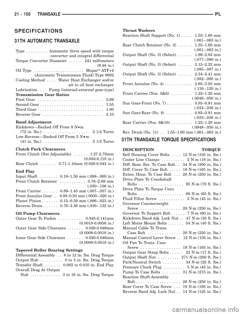
SPECIFICATIONS
31TH AUTOMATIC TRANSAXLE
Type .........Automatic three speed with torque
converter and integral differential
Torque Converter Diameter...... 241millimeters
(9.48 in.)
OilType .....................MopartATF+4
(Automatic Transmission Fluid) Type 9602
Cooling Method.... Water Heat Exchanger and/or
air to oil heat exchanger
Lubrication . . . Pump (internal-external gear-type)
Transmission Gear Ratios
First Gear............................2.69
Second Gear...........................1.55
Third Gear............................1.00
Reverse Gear..........................2.10
Band Adjustment
KickdownÐBacked Off From 8 N²m
(72 in. lbs.).................... 21/4Turns
Low-ReverseÐBacked Off From 5 N²m
(41 in. lbs.).................... 31/2Turns
Clutch Pack Clearances
Front Clutch (Not Adjustable)......1.27-2.79mm
(0.050-0.110 in.)
Rear Clutch.......0.71-1.10mm (0.028-0.043 in.)
End Play
Input Shaft........0.19±1.50 mm (.008±.060 in.)
Front Clutch Retainer...........0.76±2.69 mm
(.030±.106 in.)
Front Carrier.......0.89±1.45 mm (.007±.057 in.)
Front Annulus Gear . . 0.09±0.50 mm (.0035±.020 in.)
Planet Pinion.......0.15±0.59 mm (.006±.023 in.)
Reverse Drum......0.76±3.36 mm (.030±.132 in.)
Oil Pump Clearances
Outer Gear To Pocket...........0.045-0.141mm
(0.0018-0.0056 in.)
Outer Gear Side Clearance.......0.020-0.046mm
(0.0008-0.0018 in.)
Inner Gear Side Clearance.......0.020-0.046mm
(0.0008-0.0018 in.)
Tapered Roller Bearing Settings
Differential Assembly . . 6 to 12 in. lbs. Drag Torque
Output Hub.......... 0to3in.lbs. Drag Torque
Transfer Shaft.......0.002 to 0.010 in. End Play
Overall Drag At Output
Hub ............. 3to16in.lbs. Drag TorqueThrust Washers
Reaction Shaft Support (No. 1).....1.55±1.60 mm
(.061±.063 in.)
Rear Clutch Retainer (No. 2)......1.55±1.60 mm
(.061±.063 in.)
Output Shaft (No. 3) (Select)......1.98±2.03 mm
(.077±.080 in.)
Output Shaft (No. 3) (Select)......2.15±2.22 mm
(.085±.087 in.)
Output Shaft (No. 3) (Select)......2.34±2.41 mm
(.092±.095 in.)
Front Annulus (No. 4)............2.95±3.05 mm
(.116±.120 in.)
Front Carrier (Nos. 5&6).........1.22±1.28 mm
(.0948±.050 in.)
Sun Gear-Front (No. 7)...........0.85±0.91 mm
(.033±.036 in.)
Sun Gear-Rear (No. 8)...........0.85±0.91 mm
(.033±.036 in.)
Rear Carrier (Nos. 9&10).........1.22±1.28 mm
(.0948±.050 in.)
Rev. Drum (No. 11) . . 1.55±1.60 mm (.061±.063 in.)
31TH TRANSAXLE TORQUE SPECIFICATIONS
DESCRIPTION TORQUE
Bell Housing Cover Bolts.... 12N´m(105 in. lbs.)
Cooler Line Clamps.......... 2N´m(18in.lbs.)
Diff. Bear. Ret. To Case Bolt . . 34 N´m (300 in. lbs.)
Diff. Cover To Case Bolt..... 19N´m(165 in. lbs.)
Exten. Hous. To Case Bolt . . . 28 N´m (250 in. lbs.)
Drive Plate To Crankshaft
Bolts................... 95N´m(70ft.lbs.)
Drive Plate To Torque Conv.
Bolts................... 88N´m(65ft.lbs.)
Fluid Filter Screw........... 5N´m(45in.lbs.)
Governor Counterweight
Screw................. 28N´m(250 in. lbs.)
Governor To Support Bolt...... 7N´m(60in.lbs.)
Kickdown Band Adj. Lock Nut . . 47 N´m (35 ft. lbs.)
Left Motor Mount Bolts....... 54N´m(40ft.lbs.)
Manual Cable To Trans.
Case Bolt.............. 28N´m(250 in. lbs.)
Manual Control Lever Screw . . 12 N´m (105 in. lbs.)
Oil Pan To Trans. Case
Screw................. 19N´m(165 in. lbs.)
Output Gear Strap Bolts...... 23N´m(17ft.lbs.)
Output Shaft Nut......... 271N´m(200 ft. lbs.)
Park/Neutral Switch......... 34N´m(25ft.lbs.)
Pressure Check Plug......... 5N´m(45in.lbs.)
Pump To Case Bolts........ 31N´m(275 in. lbs.)
Reaction Shaft Assembly
Bolt................... 28N´m(250 in. lbs.)
Rear Cover To Case Screw . . . 19 N´m (165 in. lbs.)
Reverse Band Adj. Lock Nut . . 14 N´m (125 in. lbs.)
21 - 150 TRANSAXLEPL
Page 1097 of 1285

(M) Check Engine Lamp (MIL) will illuminate during engine operation if this Diagnostic Trouble Code was recorded.
P0456 Evap Leak Monitor Small Leak
Detected
P0460 Fuel Level Unit No Change Over
MilesNo movement of fuel level sender detected.
P0461 Fuel Level Unit No Changeover
TimeNo level of fuel level sender detected.
P0462 Fuel Level Sending Unit Volts Too
LowFuel level sensor input below acceptable voltage.
P0463 Fuel Level Sending Unit Volts Too
HighFuel level sensor input above acceptable voltage.
P0500 (M) No Vehicle Speed Sensor Signal No vehicle speed sensor signal detected during road
load conditions.
P0505 (M) Idle Air Control Motor Circuits Replace
P0522 Oil Pressure Sens Low Oil pressure sensor input below acceptable voltage.
P0523 Oil Pressure Sens High Oil pressure sensor input above acceptable voltage.
P0551 (M) Power Steering Switch Failure Incorrect input state detected for the power steering
switch circuit. PL: High pressure seen at high speed.
P0600 (M) PCM Failure SPI Communications No communication detected between co-processors in
the control module.
P0601 (M) Internal Controller Failure Internal control module fault condition (check sum)
detected.
P0604 Internal Trans Controller Transmission control module RAM self test fault
detected. -Aisin transmission.
P0605 Internal Trans Controller Transmission control module ROM self test fault
detected -Aisin transmission.
P0622 (G) Generator Field Not Switching
ProperlyAn open or shorted condition detected in the generator
field control circuit.
P0645 A/C Clutch Relay Circuit An open or shorted condition detected in the A/C clutch
relay control circuit.
P0700 (M) EATX Controller DTC Present This SBEC III or JTEC DTC indicates that the EATX or
Aisin controller has an active fault and has illuminated
the MIL via a CCD (EATX) or SCI (Aisin) message. The
specific fault must be acquired from the EATX via CCD
or from the Aisin via ISO-9141.
P0703 (M) Brake Switch Stuck Pressed or
ReleasedIncorrect input state detected in the brake switch circuit.
(Changed from P1595).
P0711 Trans Temp Sensor, No Temp Rise
After StartRelationship between the transmission temperature and
overdrive operation and/or TCC operation indicates a
failure of the Transmission Temperature Sensor. OBD II
Rationality.
P0712 Trans Temp Sensor Voltage Too
LowTransmission fluid temperature sensor input below
acceptable voltage.
P0713 Trans Temp Sensor Voltage Too
HighTransmission fluid temperature sensor input above
acceptable voltage.
P0720 Low Output SPD Sensor RPM,
Above 15 MPHThe relationship between the Output Shaft Speed
Sensor and vehicle speed is not within acceptable
limits.
25 - 10 EMISSION CONTROL SYSTEMSPL
DESCRIPTION AND OPERATION (Continued)
Page 1107 of 1285
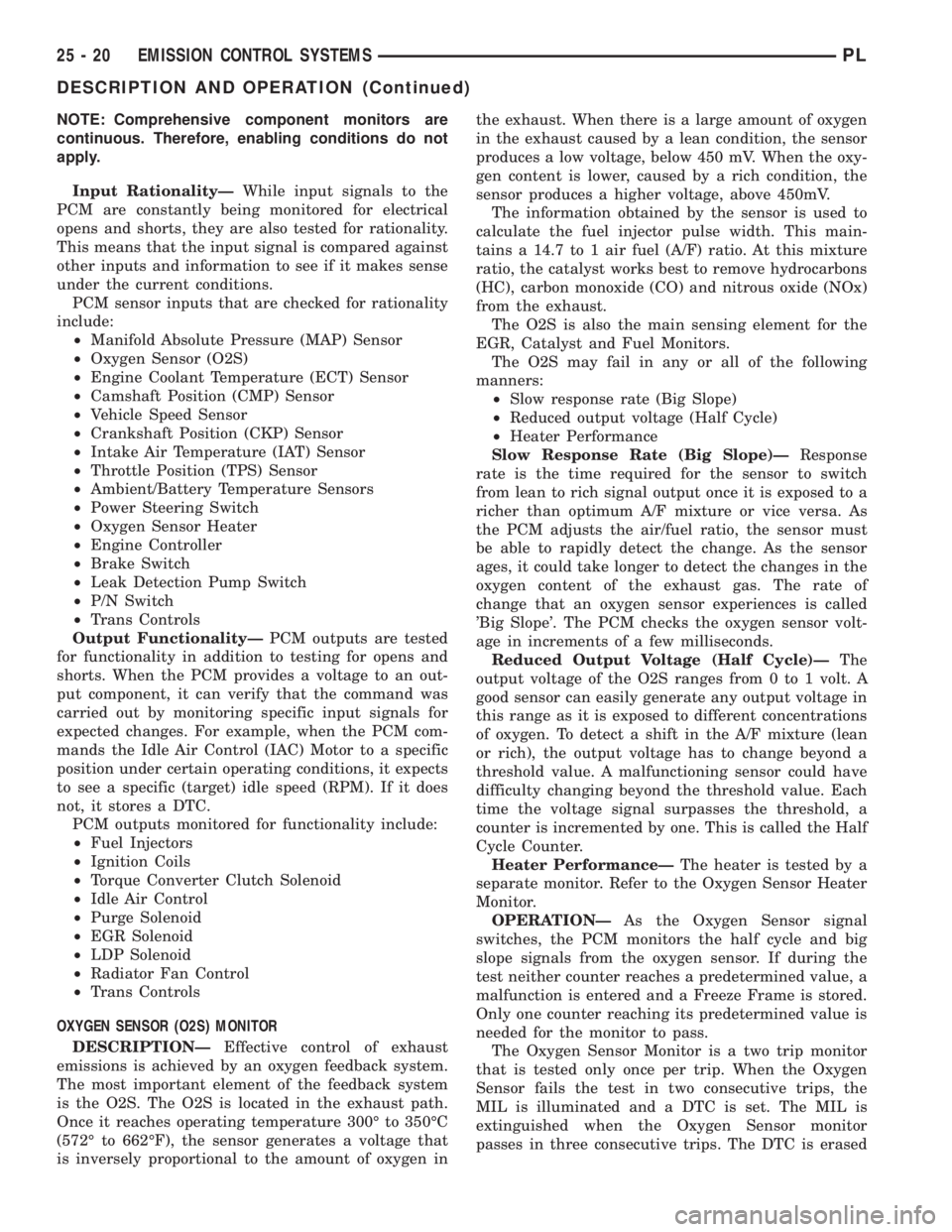
NOTE: Comprehensive component monitors are
continuous. Therefore, enabling conditions do not
apply.
Input RationalityÐWhile input signals to the
PCM are constantly being monitored for electrical
opens and shorts, they are also tested for rationality.
This means that the input signal is compared against
other inputs and information to see if it makes sense
under the current conditions.
PCM sensor inputs that are checked for rationality
include:
²Manifold Absolute Pressure (MAP) Sensor
²Oxygen Sensor (O2S)
²Engine Coolant Temperature (ECT) Sensor
²Camshaft Position (CMP) Sensor
²Vehicle Speed Sensor
²Crankshaft Position (CKP) Sensor
²Intake Air Temperature (IAT) Sensor
²Throttle Position (TPS) Sensor
²Ambient/Battery Temperature Sensors
²Power Steering Switch
²Oxygen Sensor Heater
²Engine Controller
²Brake Switch
²Leak Detection Pump Switch
²P/N Switch
²Trans Controls
Output FunctionalityÐPCM outputs are tested
for functionality in addition to testing for opens and
shorts. When the PCM provides a voltage to an out-
put component, it can verify that the command was
carried out by monitoring specific input signals for
expected changes. For example, when the PCM com-
mands the Idle Air Control (IAC) Motor to a specific
position under certain operating conditions, it expects
to see a specific (target) idle speed (RPM). If it does
not, it stores a DTC.
PCM outputs monitored for functionality include:
²Fuel Injectors
²Ignition Coils
²Torque Converter Clutch Solenoid
²Idle Air Control
²Purge Solenoid
²EGR Solenoid
²LDP Solenoid
²Radiator Fan Control
²Trans Controls
OXYGEN SENSOR (O2S) MONITOR
DESCRIPTIONÐEffective control of exhaust
emissions is achieved by an oxygen feedback system.
The most important element of the feedback system
is the O2S. The O2S is located in the exhaust path.
Once it reaches operating temperature 300É to 350ÉC
(572É to 662ÉF), the sensor generates a voltage that
is inversely proportional to the amount of oxygen inthe exhaust. When there is a large amount of oxygen
in the exhaust caused by a lean condition, the sensor
produces a low voltage, below 450 mV. When the oxy-
gen content is lower, caused by a rich condition, the
sensor produces a higher voltage, above 450mV.
The information obtained by the sensor is used to
calculate the fuel injector pulse width. This main-
tains a 14.7 to 1 air fuel (A/F) ratio. At this mixture
ratio, the catalyst works best to remove hydrocarbons
(HC), carbon monoxide (CO) and nitrous oxide (NOx)
from the exhaust.
The O2S is also the main sensing element for the
EGR, Catalyst and Fuel Monitors.
The O2S may fail in any or all of the following
manners:
²Slow response rate (Big Slope)
²Reduced output voltage (Half Cycle)
²Heater Performance
Slow Response Rate (Big Slope)ÐResponse
rate is the time required for the sensor to switch
from lean to rich signal output once it is exposed to a
richer than optimum A/F mixture or vice versa. As
the PCM adjusts the air/fuel ratio, the sensor must
be able to rapidly detect the change. As the sensor
ages, it could take longer to detect the changes in the
oxygen content of the exhaust gas. The rate of
change that an oxygen sensor experiences is called
'Big Slope'. The PCM checks the oxygen sensor volt-
age in increments of a few milliseconds.
Reduced Output Voltage (Half Cycle)ÐThe
output voltage of the O2S ranges from 0 to 1 volt. A
good sensor can easily generate any output voltage in
this range as it is exposed to different concentrations
of oxygen. To detect a shift in the A/F mixture (lean
or rich), the output voltage has to change beyond a
threshold value. A malfunctioning sensor could have
difficulty changing beyond the threshold value. Each
time the voltage signal surpasses the threshold, a
counter is incremented by one. This is called the Half
Cycle Counter.
Heater PerformanceÐThe heater is tested by a
separate monitor. Refer to the Oxygen Sensor Heater
Monitor.
OPERATIONÐAs the Oxygen Sensor signal
switches, the PCM monitors the half cycle and big
slope signals from the oxygen sensor. If during the
test neither counter reaches a predetermined value, a
malfunction is entered and a Freeze Frame is stored.
Only one counter reaching its predetermined value is
needed for the monitor to pass.
The Oxygen Sensor Monitor is a two trip monitor
that is tested only once per trip. When the Oxygen
Sensor fails the test in two consecutive trips, the
MIL is illuminated and a DTC is set. The MIL is
extinguished when the Oxygen Sensor monitor
passes in three consecutive trips. The DTC is erased
25 - 20 EMISSION CONTROL SYSTEMSPL
DESCRIPTION AND OPERATION (Continued)
Page 1108 of 1285
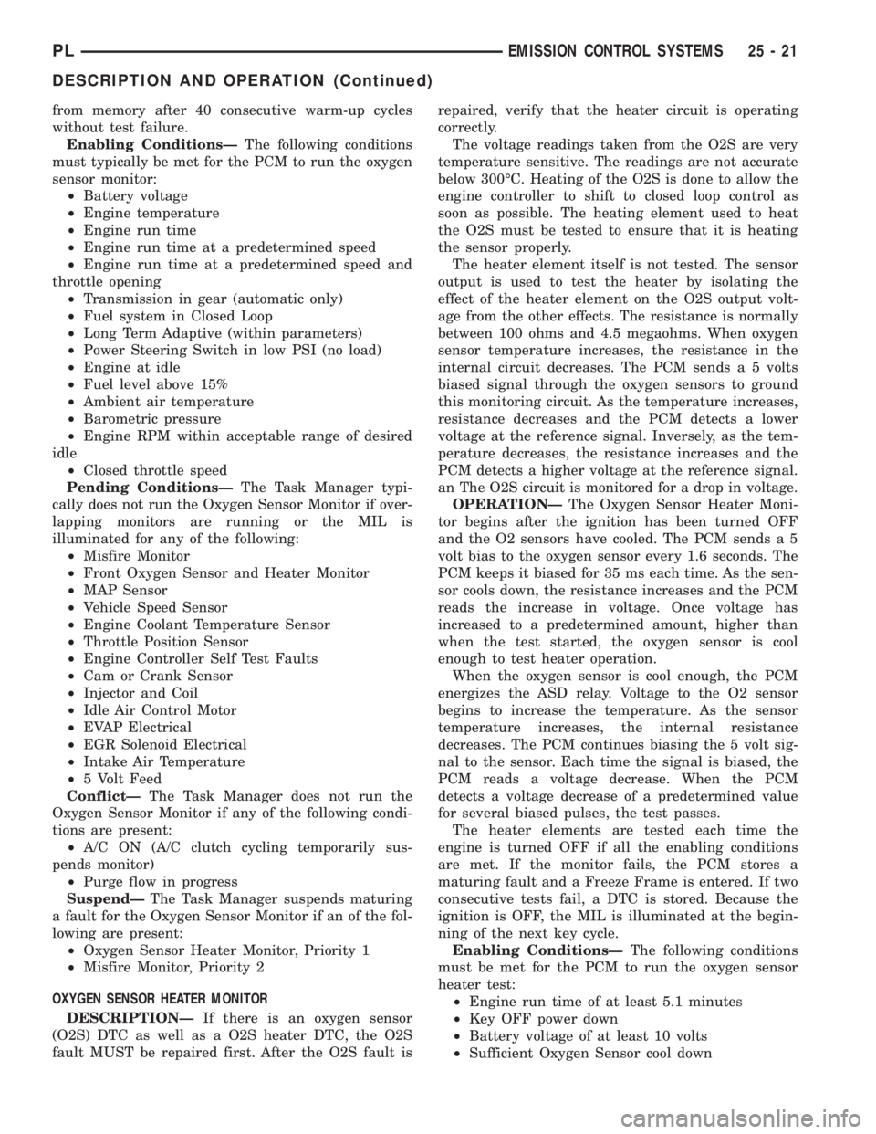
from memory after 40 consecutive warm-up cycles
without test failure.
Enabling ConditionsÐThe following conditions
must typically be met for the PCM to run the oxygen
sensor monitor:
²Battery voltage
²Engine temperature
²Engine run time
²Engine run time at a predetermined speed
²Engine run time at a predetermined speed and
throttle opening
²Transmission in gear (automatic only)
²Fuel system in Closed Loop
²Long Term Adaptive (within parameters)
²Power Steering Switch in low PSI (no load)
²Engine at idle
²Fuel level above 15%
²Ambient air temperature
²Barometric pressure
²Engine RPM within acceptable range of desired
idle
²Closed throttle speed
Pending ConditionsÐThe Task Manager typi-
cally does not run the Oxygen Sensor Monitor if over-
lapping monitors are running or the MIL is
illuminated for any of the following:
²Misfire Monitor
²Front Oxygen Sensor and Heater Monitor
²MAP Sensor
²Vehicle Speed Sensor
²Engine Coolant Temperature Sensor
²Throttle Position Sensor
²Engine Controller Self Test Faults
²Cam or Crank Sensor
²Injector and Coil
²Idle Air Control Motor
²EVAP Electrical
²EGR Solenoid Electrical
²Intake Air Temperature
²5 Volt Feed
ConflictÐThe Task Manager does not run the
Oxygen Sensor Monitor if any of the following condi-
tions are present:
²A/C ON (A/C clutch cycling temporarily sus-
pends monitor)
²Purge flow in progress
SuspendÐThe Task Manager suspends maturing
a fault for the Oxygen Sensor Monitor if an of the fol-
lowing are present:
²Oxygen Sensor Heater Monitor, Priority 1
²Misfire Monitor, Priority 2
OXYGEN SENSOR HEATER MONITOR
DESCRIPTIONÐIf there is an oxygen sensor
(O2S) DTC as well as a O2S heater DTC, the O2S
fault MUST be repaired first. After the O2S fault isrepaired, verify that the heater circuit is operating
correctly.
The voltage readings taken from the O2S are very
temperature sensitive. The readings are not accurate
below 300ÉC. Heating of the O2S is done to allow the
engine controller to shift to closed loop control as
soon as possible. The heating element used to heat
the O2S must be tested to ensure that it is heating
the sensor properly.
The heater element itself is not tested. The sensor
output is used to test the heater by isolating the
effect of the heater element on the O2S output volt-
age from the other effects. The resistance is normally
between 100 ohms and 4.5 megaohms. When oxygen
sensor temperature increases, the resistance in the
internal circuit decreases. The PCM sends a 5 volts
biased signal through the oxygen sensors to ground
this monitoring circuit. As the temperature increases,
resistance decreases and the PCM detects a lower
voltage at the reference signal. Inversely, as the tem-
perature decreases, the resistance increases and the
PCM detects a higher voltage at the reference signal.
an The O2S circuit is monitored for a drop in voltage.
OPERATIONÐThe Oxygen Sensor Heater Moni-
tor begins after the ignition has been turned OFF
and the O2 sensors have cooled. The PCM sends a 5
volt bias to the oxygen sensor every 1.6 seconds. The
PCM keeps it biased for 35 ms each time. As the sen-
sor cools down, the resistance increases and the PCM
reads the increase in voltage. Once voltage has
increased to a predetermined amount, higher than
when the test started, the oxygen sensor is cool
enough to test heater operation.
When the oxygen sensor is cool enough, the PCM
energizes the ASD relay. Voltage to the O2 sensor
begins to increase the temperature. As the sensor
temperature increases, the internal resistance
decreases. The PCM continues biasing the 5 volt sig-
nal to the sensor. Each time the signal is biased, the
PCM reads a voltage decrease. When the PCM
detects a voltage decrease of a predetermined value
for several biased pulses, the test passes.
The heater elements are tested each time the
engine is turned OFF if all the enabling conditions
are met. If the monitor fails, the PCM stores a
maturing fault and a Freeze Frame is entered. If two
consecutive tests fail, a DTC is stored. Because the
ignition is OFF, the MIL is illuminated at the begin-
ning of the next key cycle.
Enabling ConditionsÐThe following conditions
must be met for the PCM to run the oxygen sensor
heater test:
²Engine run time of at least 5.1 minutes
²Key OFF power down
²Battery voltage of at least 10 volts
²Sufficient Oxygen Sensor cool down
PLEMISSION CONTROL SYSTEMS 25 - 21
DESCRIPTION AND OPERATION (Continued)
Page 1110 of 1285
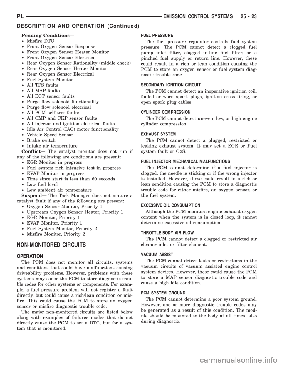
Pending ConditionsÐ
²Misfire DTC
²Front Oxygen Sensor Response
²Front Oxygen Sensor Heater Monitor
²Front Oxygen Sensor Electrical
²Rear Oxygen Sensor Rationality (middle check)
²Rear Oxygen Sensor Heater Monitor
²Rear Oxygen Sensor Electrical
²Fuel System Monitor
²All TPS faults
²All MAP faults
²All ECT sensor faults
²Purge flow solenoid functionality
²Purge flow solenoid electrical
²All PCM self test faults
²All CMP and CKP sensor faults
²All injector and ignition electrical faults
²Idle Air Control (IAC) motor functionality
²Vehicle Speed Sensor
²Brake switch
²Intake air temperature
ConflictÐThe catalyst monitor does not run if
any of the following are conditions are present:
²EGR Monitor in progress
²Fuel system rich intrusive test in progress
²EVAP Monitor in progress
²Time since start is less than 60 seconds
²Low fuel level
²Low ambient air temperature
SuspendÐThe Task Manager does not mature a
catalyst fault if any of the following are present:
²Oxygen Sensor Monitor, Priority 1
²Upstream Oxygen Sensor Heater, Priority 1
²EGR Monitor, Priority 1
²EVAP Monitor, Priority 1
²Fuel System Monitor, Priority 2
²Misfire Monitor, Priority 2
NON-MONITORED CIRCUITS
OPERATION
The PCM does not monitor all circuits, systems
and conditions that could have malfunctions causing
driveability problems. However, problems with these
systems may cause the PCM to store diagnostic trou-
ble codes for other systems or components. For exam-
ple, a fuel pressure problem will not register a fault
directly, but could cause a rich/lean condition or mis-
fire. This could cause the PCM to store an oxygen
sensor or misfire diagnostic trouble code.
The major non-monitored circuits are listed below
along with examples of failures modes that do not
directly cause the PCM to set a DTC, but for a sys-
tem that is monitored.FUEL PRESSURE
The fuel pressure regulator controls fuel system
pressure. The PCM cannot detect a clogged fuel
pump inlet filter, clogged in-line fuel filter, or a
pinched fuel supply or return line. However, these
could result in a rich or lean condition causing the
PCM to store an oxygen sensor or fuel system diag-
nostic trouble code.
SECONDARY IGNITION CIRCUIT
The PCM cannot detect an inoperative ignition coil,
fouled or worn spark plugs, ignition cross firing, or
open spark plug cables.
CYLINDER COMPRESSION
The PCM cannot detect uneven, low, or high engine
cylinder compression.
EXHAUST SYSTEM
The PCM cannot detect a plugged, restricted or
leaking exhaust system. It may set a EGR or Fuel
system fault or O2S.
FUEL INJECTOR MECHANICAL MALFUNCTIONS
The PCM cannot determine if a fuel injector is
clogged, the needle is sticking or if the wrong injector
is installed. However, these could result in a rich or
lean condition causing the PCM to store a diagnostic
trouble code for either misfire, an oxygen sensor, or
the fuel system.
EXCESSIVE OIL CONSUMPTION
Although the PCM monitors engine exhaust oxygen
content when the system is in closed loop, it cannot
determine excessive oil consumption.
THROTTLE BODY AIR FLOW
The PCM cannot detect a clogged or restricted air
cleaner inlet or filter element.
VACUUM ASSIST
The PCM cannot detect leaks or restrictions in the
vacuum circuits of vacuum assisted engine control
system devices. However, these could cause the PCM
to store a MAP sensor diagnostic trouble code and
cause a high idle condition.
PCM SYSTEM GROUND
The PCM cannot determine a poor system ground.
However, one or more diagnostic trouble codes may
be generated as a result of this condition. The mod-
ule should be mounted to the body at all times, also
during diagnostic.
PLEMISSION CONTROL SYSTEMS 25 - 23
DESCRIPTION AND OPERATION (Continued)
Page 1150 of 1285
FRONT DOOR OUTSIDE HANDLE
REMOVAL
(1) Remove door trim panel and water dam.
(2) Close door glass.
(3) Disconnect lock and latch rods from door latch.
(4) Remove nut attaching door handle retainer to
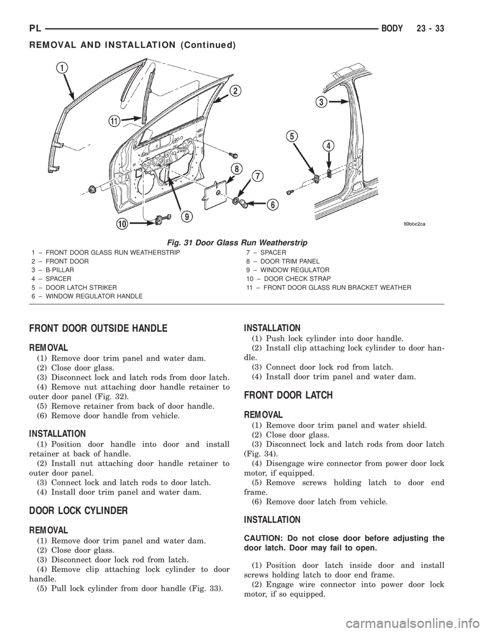
outer door panel (Fig. 32).
(5) Remove retainer from back of door handle.
(6) Remove door handle from vehicle.
INSTALLATION
(1) Position door handle into door and install
retainer at back of handle.
(2) Install nut attaching door handle retainer to
outer door panel.
(3) Connect lock and latch rods to door latch.
(4) Install door trim panel and water dam.
DOOR LOCK CYLINDER
REMOVAL
(1) Remove door trim panel and water dam.
(2) Close door glass.
(3) Disconnect door lock rod from latch.
(4) Remove clip attaching lock cylinder to door
handle.
(5) Pull lock cylinder from door handle (Fig. 33).
INSTALLATION
(1) Push lock cylinder into door handle.
(2) Install clip attaching lock cylinder to door han-
dle.
(3) Connect door lock rod from latch.
(4) Install door trim panel and water dam.
FRONT DOOR LATCH
REMOVAL
(1) Remove door trim panel and water shield.
(2) Close door glass.
(3) Disconnect lock and latch rods from door latch
(Fig. 34).
(4) Disengage wire connector from power door lock
motor, if equipped.
(5) Remove screws holding latch to door end
frame.
(6) Remove door latch from vehicle.
INSTALLATION
CAUTION: Do not close door before adjusting the
door latch. Door may fail to open.
(1) Position door latch inside door and install
screws holding latch to door end frame.
(2) Engage wire connector into power door lock
motor, if so equipped.
Fig. 31 Door Glass Run Weatherstrip
1 ± FRONT DOOR GLASS RUN WEATHERSTRIP
2 ± FRONT DOOR
3 ± B-PILLAR
4 ± SPACER
5 ± DOOR LATCH STRIKER
6 ± WINDOW REGULATOR HANDLE7 ± SPACER
8 ± DOOR TRIM PANEL
9 ± WINDOW REGULATOR
10 ± DOOR CHECK STRAP
11 ± FRONT DOOR GLASS RUN BRACKET WEATHER
PLBODY 23 - 33
REMOVAL AND INSTALLATION (Continued)
Page 1207 of 1285
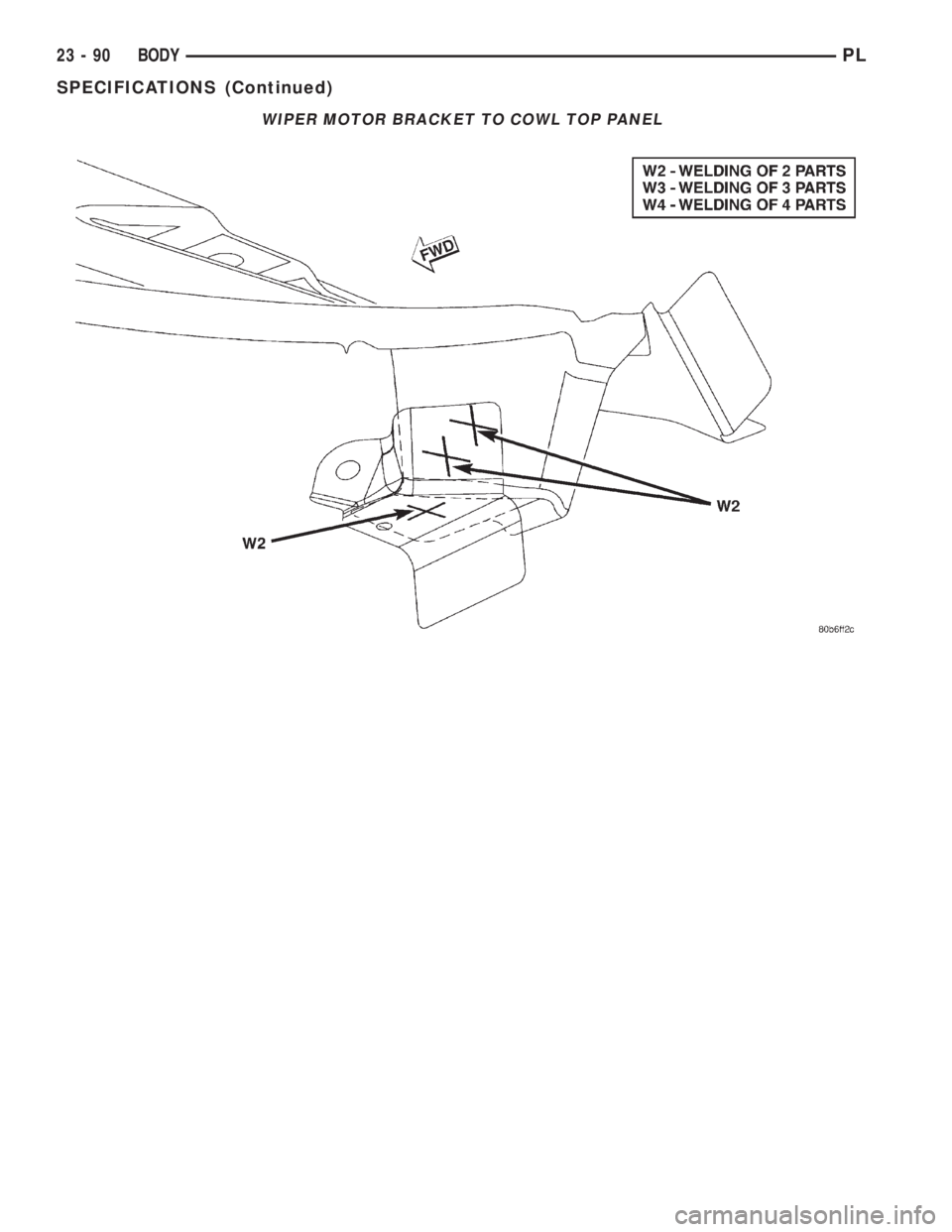
WIPER MOTOR BRACKET TO COWL TOP PANEL
23 - 90 BODYPL
SPECIFICATIONS (Continued)
Page 1232 of 1285
HEATING AND AIR CONDITIONING
TABLE OF CONTENTS
page page
GENERAL INFORMATION
A/C APPLICATION TABLE...................2
HEATER AND AIR CONDITIONING CONTROL...2
HEATER AND AIR CONDITIONING............2
INTRODUCTION..........................3
SAFETY PRECAUTIONS AND WARNINGS......4
DESCRIPTION AND OPERATION
A/C REFRIGERANT LINES..................4
BLOWER MOTOR RESISTOR................5
COMPRESSOR...........................5
COMPRESSOR FRONT SHAFT SEAL..........6
CONDENSATION DRAIN TUBE...............6
ENGINE COOLING SYSTEM REQUIREMENTS...6
EVAPORATOR PROBE......................6
HANDLING TUBING AND FITTINGS...........6
HIGH PRESSURE CUT OUT SWITCH..........6
LOW PRESSURE CUT OFF SWITCH..........6
SIDE WINDOW DEMISTERS................7
SYSTEM AIRFLOW........................7
SYSTEM OIL LEVEL.......................7
VACUUM CONTROL SYSTEM................8
DIAGNOSIS AND TESTING
A/C PERFORMANCE TEST..................9
BLOWER MOTOR ELECTRICAL DIAGNOSIS....9
BLOWER MOTOR VIBRATION AND/OR
NOISE DIAGNOSIS.....................11
COMPRESSOR NOISE DIAGNOSIS..........11
EVAPORATOR PROBE TEST................11
EXPANSION VALVE.......................11
HEATER PERFORMANCE TEST.............13
LOW PRESSURE CUT OFF SWITCH.........14
SYSTEM CHARGE LEVEL TEST.............14
VACUUM CONTROL SYSTEM...............15
SERVICE PROCEDURES
CHARGING A/C SYSTEM..................17EVACUATING REFRIGERANT SYSTEM........18
R-134a REFRIGERANT....................19
SERVICING REFRIGERANT OIL LEVEL.......19
SYSTEM LEAK CHECKING.................20
REMOVAL AND INSTALLATION
A/C FILTER/DRIER.......................20
A/C SERVICE PORT VALVE CORES..........21
BLOWER MOTOR AND WHEEL ASSEMBLY....21
BLOWER MOTOR RESISTOR...............22
BLOWER MOTOR WHEEL.................22
COMPRESSOR..........................22
COMPRESSOR CLUTCH/COIL ASSEMBLY.....23
CONDENSATION DRAIN TUBE..............25
CONDENSER............................25
DISCHARGE LINE........................26
EVAPORATOR...........................26
EVAPORATOR PROBE.....................26
EXPANSION VALVE.......................27
HEATER CORE..........................28
HEATER HOSES.........................28
HIGH PRESSURE CUT OUT SWITCH.........29
HIGH PRESSURE RELIEF VALVE............29
LIQUID LINE............................29
LOW PRESSURE CUT OFF SWITCH.........29
MODE CONTROL CABLE..................30
RECIRCULATION DOOR ACTUATOR.........31
SUCTION LINE..........................31
TEMPERATURE CONTROL CABLE...........32
UNIT HOUSING..........................32
DISASSEMBLY AND ASSEMBLY
HEATER-A/C HOUSING....................34
ADJUSTMENTS
MODE CONTROL CABLE..................34
TEMPERATURE CONTROL CABLE...........34
PLHEATING AND AIR CONDITIONING 24 - 1