Page 1269 of 1285

(15) Remove the heater core cover from the hous-
ing assembly.
(16) Remove the coolant lines from the heater core.
(17) Remove the screws necessary to disassemble
the A/C-Heater housing assembly.
(18) Remove the evaporator coil from the A/C-
Heater housing (Fig. 3).
INSTALLATION
NOTE: When the evaporator coil is replaced, some
refrigerant oil will remain in the old evaporator. This
oil must be replaced before the system is operated.
(1) Install the evaporator coil in the A/C-Heater
housing (Fig. 4). Be certain all seals are replaced in
there original positions.
(2) Reassemble the A/C-Heater housing.
(3) Install the housing in the vehicle and install
the retaining bolts. Torque the bolts to 20 N´m (177
in. lbs.).
(4) Connect the electrical connectors on the A/C-
Heater housing.
(5) Install the defroster duct on the A/C-Heater
housing and secure at the body attachment point.
(6) Working from inside the engine compartment,
install the A/C-Heater housing drain tube and retain-
ing clip.
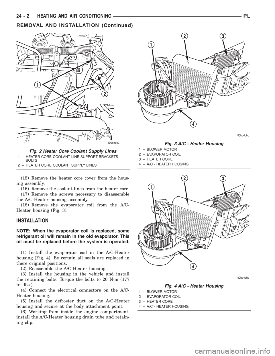
Fig. 2 Heater Core Coolant Supply Lines
1 ± HEATER CORE COOLANT LINE SUPPORT BRACKETS
BOLTS
2 ± HEATER CORE COOLANT SUPPLY LINES
Fig. 3 A/C - Heater Housing
1 ± BLOWER MOTOR
2 ± EVAPORATOR COIL
3 ± HEATER CORE
4 ± A/C - HEATER HOUSING
Fig. 4 A/C - Heater Housing
1 ± BLOWER MOTOR
2 ± EVAPORATOR COIL
3 ± HEATER CORE
4 ± A/C - HEATER HOUSING
24 - 2 HEATING AND AIR CONDITIONINGPL
REMOVAL AND INSTALLATION (Continued)
Page 1271 of 1285

(8) Remove the heater core coolant supply hoses
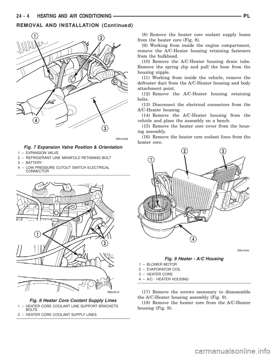
from the heater core (Fig. 8).
(9) Working from inside the engine compartment,
remove the A/C-Heater housing retaining fasteners
from the bulkhead.
(10) Remove the A/C-Heater housing drain tube.
Remove the spring clip and pull the hose from the
housing nipple.
(11) Working from inside the vehicle, remove the
defroster duct from the A/C-Heater housing and body
attachment point.
(12) Remove the A/C-Heater housing retaining
bolts.
(13) Disconnect the electrical connectors from the
A/C-Heater housing.
(14) Remove the A/C-Heater housing from the
vehicle and place the assembly on a bench.
(15) Remove the heater core cover from the hous-
ing assembly.
(16) Remove the heater core coolant lines from the
heater core.
(17) Remove the screws necessary to disassemble
the A/C-Heater housing assembly (Fig. 9).
(18) Remove the heater core from the A/C-Heater
housing (Fig. 9).
Fig. 7 Expansion Valve Position & Orientation
1 ± EXPANSION VALVE
2 ± REFRIGERANT LINE MANIFOLD RETAINING BOLT
3 ± BATTERY
4 ± LOW PRESSURE CUTOUT SWITCH ELECTRICAL
CONNECTOR
Fig. 8 Heater Core Coolant Supply Lines
1 ± HEATER CORE COOLANT LINE SUPPORT BRACKETS
BOLTS
2 ± HEATER CORE COOLANT SUPPLY LINES
Fig. 9 Heater - A/C Housing
1 ± BLOWER MOTOR
2 ± EVAPORATOR COIL
3 ± HEATER CORE
4 ± A/C - HEATER HOUSING
24 - 4 HEATING AND AIR CONDITIONINGPL
REMOVAL AND INSTALLATION (Continued)
Page 1272 of 1285

INSTALLATION
(1) Install the heater core in the A/C-Heater hous-
ing.
(2) Reassemble the A/C-Heater housing.
(3) Install the housing in the vehicle and install
the retaining bolts. Torque the bolts to 20 N´m (177
in. lbs.).
(4) Connect the electrical connectors on the A/C-
Heater housing.
(5) Install the defroster duct on the A/C-Heater
housing and secure at the body attachment point.
(6) Install the A/C-Heater housing drain tube and
retaining clip.
(7) Install the A/C-Heater housing retaining fas-
teners. Torque the fasteners to 20 N´m (177 in. lbs.).
(8) Install the heater core coolant supply hoses on
the heater core (Fig. 11).
(9) Install the expansion valve, gasket and retain-
ing bolts. Torque the bolts to 11 N´m (97 in. lbs.).
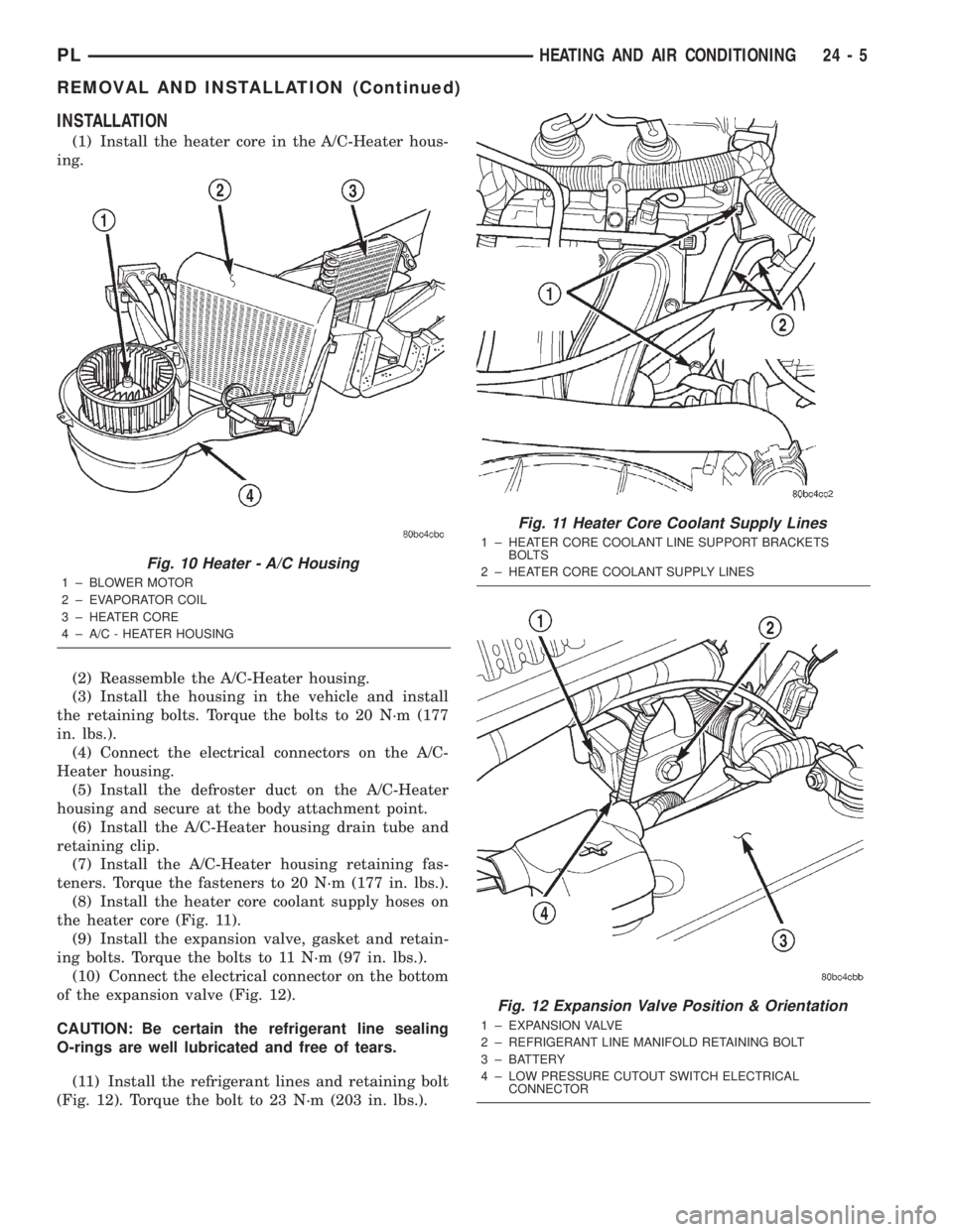
(10) Connect the electrical connector on the bottom
of the expansion valve (Fig. 12).
CAUTION: Be certain the refrigerant line sealing
O-rings are well lubricated and free of tears.
(11) Install the refrigerant lines and retaining bolt
(Fig. 12). Torque the bolt to 23 N´m (203 in. lbs.).
Fig. 10 Heater - A/C Housing
1 ± BLOWER MOTOR
2 ± EVAPORATOR COIL
3 ± HEATER CORE
4 ± A/C - HEATER HOUSING
Fig. 11 Heater Core Coolant Supply Lines
1 ± HEATER CORE COOLANT LINE SUPPORT BRACKETS
BOLTS
2 ± HEATER CORE COOLANT SUPPLY LINES
Fig. 12 Expansion Valve Position & Orientation
1 ± EXPANSION VALVE
2 ± REFRIGERANT LINE MANIFOLD RETAINING BOLT
3 ± BATTERY
4 ± LOW PRESSURE CUTOUT SWITCH ELECTRICAL
CONNECTOR
PLHEATING AND AIR CONDITIONING 24 - 5
REMOVAL AND INSTALLATION (Continued)