2000 DODGE NEON key
[x] Cancel search: keyPage 214 of 1285
be checked. To determine if a high current draw con-
dition exists first check the vehicle with a test lamp.
(1) Verify that all electrical accessories are OFF.
²Remove key from ignition switch
²Turn off all lights
²Trunk lid is closed
²Engine compartment hood lamp is disconnected
or lamp removed
²Map lamp on rear view mirror
²Glove box door is closed
²Sun visor vanity lights are OFF
²All doors are closed
²Allow the ignition key lamp system to time out
in approximately 30 seconds, if equipped.
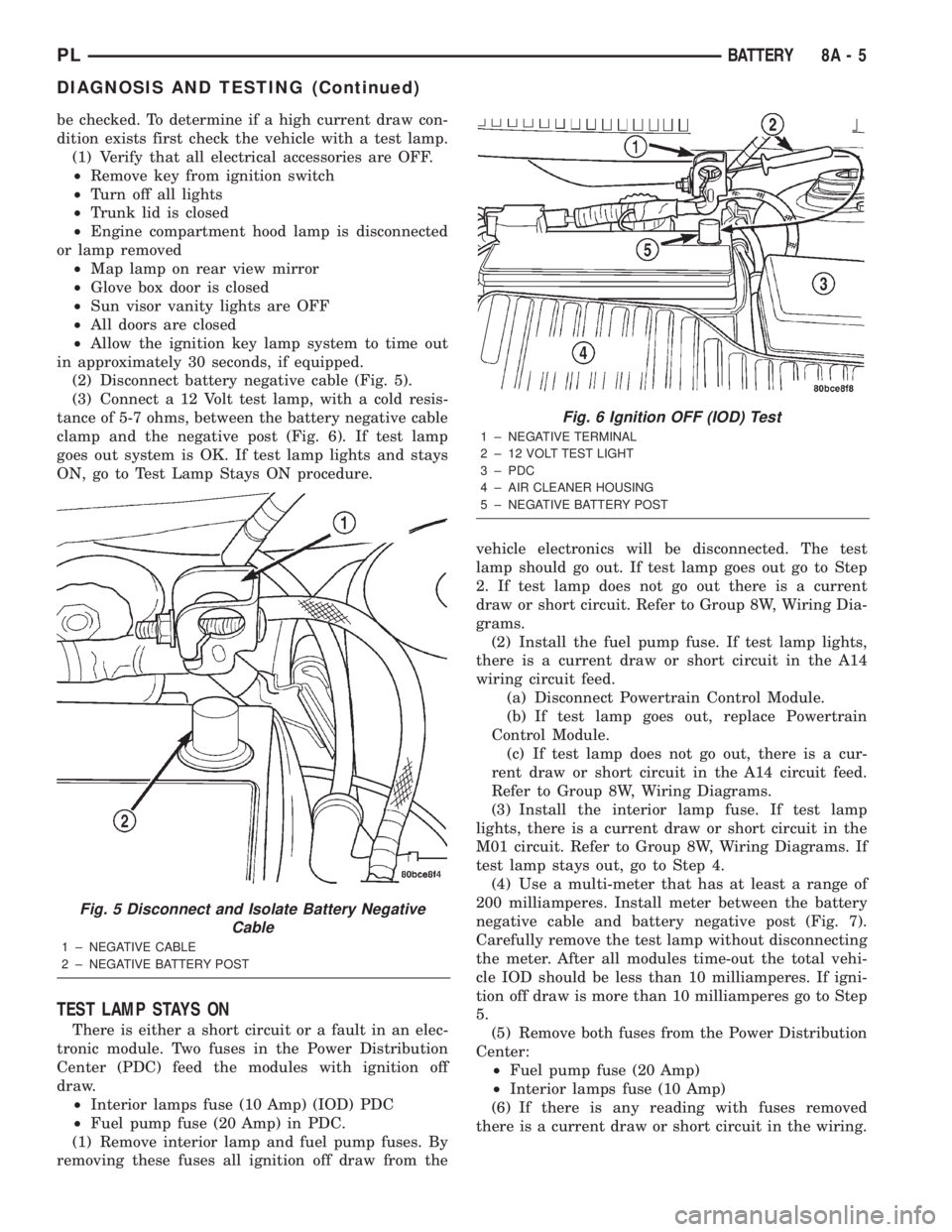
(2) Disconnect battery negative cable (Fig. 5).
(3) Connect a 12 Volt test lamp, with a cold resis-
tance of 5-7 ohms, between the battery negative cable
clamp and the negative post (Fig. 6). If test lamp
goes out system is OK. If test lamp lights and stays
ON, go to Test Lamp Stays ON procedure.
TEST LAMP STAYS ON
There is either a short circuit or a fault in an elec-
tronic module. Two fuses in the Power Distribution
Center (PDC) feed the modules with ignition off
draw.
²Interior lamps fuse (10 Amp) (IOD) PDC
²Fuel pump fuse (20 Amp) in PDC.
(1) Remove interior lamp and fuel pump fuses. By
removing these fuses all ignition off draw from thevehicle electronics will be disconnected. The test
lamp should go out. If test lamp goes out go to Step
2. If test lamp does not go out there is a current
draw or short circuit. Refer to Group 8W, Wiring Dia-
grams.
(2) Install the fuel pump fuse. If test lamp lights,
there is a current draw or short circuit in the A14
wiring circuit feed.
(a) Disconnect Powertrain Control Module.
(b) If test lamp goes out, replace Powertrain
Control Module.
(c) If test lamp does not go out, there is a cur-
rent draw or short circuit in the A14 circuit feed.
Refer to Group 8W, Wiring Diagrams.
(3) Install the interior lamp fuse. If test lamp
lights, there is a current draw or short circuit in the
M01 circuit. Refer to Group 8W, Wiring Diagrams. If
test lamp stays out, go to Step 4.
(4) Use a multi-meter that has at least a range of
200 milliamperes. Install meter between the battery
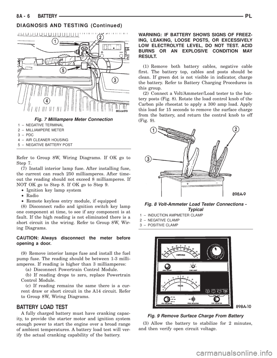
negative cable and battery negative post (Fig. 7).
Carefully remove the test lamp without disconnecting
the meter. After all modules time-out the total vehi-
cle IOD should be less than 10 milliamperes. If igni-
tion off draw is more than 10 milliamperes go to Step
5.
(5) Remove both fuses from the Power Distribution
Center:
²Fuel pump fuse (20 Amp)
²Interior lamps fuse (10 Amp)
(6) If there is any reading with fuses removed
there is a current draw or short circuit in the wiring.
Fig. 5 Disconnect and Isolate Battery Negative
Cable
1 ± NEGATIVE CABLE
2 ± NEGATIVE BATTERY POST
Fig. 6 Ignition OFF (IOD) Test
1 ± NEGATIVE TERMINAL
2 ± 12 VOLT TEST LIGHT
3 ± PDC
4 ± AIR CLEANER HOUSING
5 ± NEGATIVE BATTERY POST
PLBATTERY 8A - 5
DIAGNOSIS AND TESTING (Continued)
Page 215 of 1285
Refer to Group 8W, Wiring Diagrams. If OK go to
Step 7.
(7) Install interior lamp fuse. After installing fuse,
the current can reach 250 milliamperes. After time-
out the reading should not exceed 8 milliamperes. If
NOT OK go to Step 8. If OK go to Step 9.
²Ignition key lamp system
²Radio
²Remote keyless entry module, if equipped
(8) Disconnect radio and ignition switch key lamp
one component at time, to see if any component is at
fault. If the high reading is not eliminated there is a
short circuit in the wiring. Refer to Group 8W, Wir-
ing Diagrams.
CAUTION: Always disconnect the meter before
opening a door.
(9) Remove interior lamps fuse and install the fuel
pump fuse. The reading should be between 1-3 milli-
amperes. If reading is higher than 3 milliamperes:
(a) Disconnect Powertrain Control Module.
(b) If reading drops to zero, replace Powertrain
Control Module.
(c) If reading remains the same there is a cur-
rent draw or short circuit in the A14 circuit. Refer
to Group 8W, Wiring Diagrams.
BATTERY LOAD TEST
A fully charged battery must have cranking capac-
ity, to provide the starter motor and ignition system
enough power to start the engine over a broad range
of ambient temperatures. A battery load test will ver-
ify the actual cranking capability of the battery.WARNING: IF BATTERY SHOWS SIGNS OF FREEZ-
ING, LEAKING, LOOSE POSTS, OR EXCESSIVELY
LOW ELECTROLYTE LEVEL, DO NOT TEST. ACID
BURNS OR AN EXPLOSIVE CONDITION MAY
RESULT.
(1) Remove both battery cables, negative cable
first. The battery top, cables and posts should be
clean. If green dot is not visible in indicator, charge
the battery. Refer to Battery Charging Procedures in
this group.
(2) Connect a Volt/Ammeter/Load tester to the bat-
tery posts (Fig. 8). Rotate the load control knob of the
Carbon pile rheostat to apply a 300 amp load. Apply
this load for 15 seconds to remove the surface charge
from the battery, and return the control knob to off
(Fig. 9).
(3) Allow the battery to stabilize for 2 minutes,
and then verify open circuit voltage.
Fig. 7 Milliampere Meter Connection
1 ± NEGATIVE TERMINAL
2 ± MILLIAMPERE METER
3 ± PDC
4 ± AIR CLEANER HOUSING
5 ± NEGATIVE BATTERY POST
Fig. 8 Volt-Ammeter Load Tester Connections -
Typical
1 ± INDUCTION AMPMETER CLAMP
2 ± NEGATIVE CLAMP
3 ± POSITIVE CLAMP
Fig. 9 Remove Surface Charge From Battery
8A - 6 BATTERYPL
DIAGNOSIS AND TESTING (Continued)
Page 225 of 1285
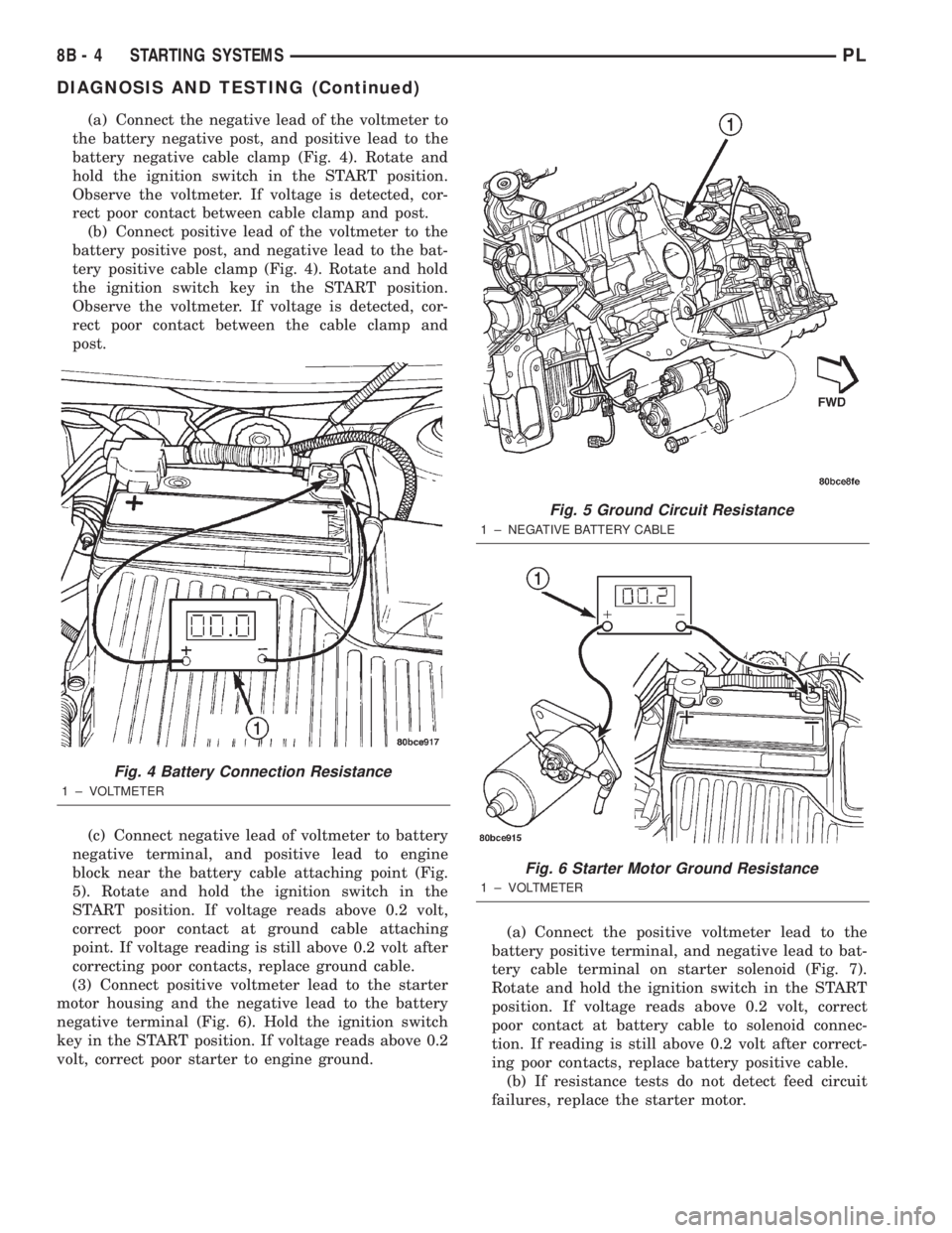
(a) Connect the negative lead of the voltmeter to
the battery negative post, and positive lead to the
battery negative cable clamp (Fig. 4). Rotate and
hold the ignition switch in the START position.
Observe the voltmeter. If voltage is detected, cor-
rect poor contact between cable clamp and post.
(b) Connect positive lead of the voltmeter to the
battery positive post, and negative lead to the bat-
tery positive cable clamp (Fig. 4). Rotate and hold
the ignition switch key in the START position.
Observe the voltmeter. If voltage is detected, cor-
rect poor contact between the cable clamp and
post.
(c) Connect negative lead of voltmeter to battery
negative terminal, and positive lead to engine
block near the battery cable attaching point (Fig.
5). Rotate and hold the ignition switch in the
START position. If voltage reads above 0.2 volt,
correct poor contact at ground cable attaching
point. If voltage reading is still above 0.2 volt after
correcting poor contacts, replace ground cable.
(3) Connect positive voltmeter lead to the starter
motor housing and the negative lead to the battery
negative terminal (Fig. 6). Hold the ignition switch
key in the START position. If voltage reads above 0.2
volt, correct poor starter to engine ground.(a) Connect the positive voltmeter lead to the
battery positive terminal, and negative lead to bat-
tery cable terminal on starter solenoid (Fig. 7).
Rotate and hold the ignition switch in the START
position. If voltage reads above 0.2 volt, correct
poor contact at battery cable to solenoid connec-
tion. If reading is still above 0.2 volt after correct-
ing poor contacts, replace battery positive cable.
(b) If resistance tests do not detect feed circuit
failures, replace the starter motor.
Fig. 4 Battery Connection Resistance
1 ± VOLTMETER
Fig. 5 Ground Circuit Resistance
1 ± NEGATIVE BATTERY CABLE
Fig. 6 Starter Motor Ground Resistance
1 ± VOLTMETER
8B - 4 STARTING SYSTEMSPL
DIAGNOSIS AND TESTING (Continued)
Page 236 of 1285
IGNITION SYSTEM
TABLE OF CONTENTS
page page
DESCRIPTION AND OPERATION
IGNITION SYSTEM........................1
SPARK PLUGS...........................1
SPARK PLUG CABLES.....................1
ELECTRONIC IGNITION COILS...............2
AUTOMATIC SHUTDOWN RELAY.............2
CRANKSHAFT POSITION SENSORÐPCM
INPUT................................3
CAMSHAFT POSITION SENSORÐPCM
INPUT................................4
KNOCK SENSOR..........................5
IGNITION SWITCH........................5
LOCK KEY CYLINDER......................5
IGNITION INTERLOCK.....................6
REMOVAL AND INSTALLATION
SPARK PLUG SERVICE....................6SPARK PLUG CABLE SERVICE..............6
IGNITION COIL...........................6
AUTOMATIC SHUTDOWN RELAY.............6
CAMSHAFT POSITION SENSOR..............6
CRANKSHAFT POSITION SENSOR............8
KNOCK SENSOR..........................8
IGNITION SWITCH........................8
LOCK KEY CYLINDER......................9
IGNITION INTERLOCK....................10
SPECIFICATIONS
VECI LABEL............................10
FIRING ORDERÐ2.0L....................10
TORQUE SPECIFICATION..................11
SPARK PLUG CABLE RESISTANCEÐSOHC....11
SPARK PLUG...........................11
IGNITION COIL..........................11
DESCRIPTION AND OPERATION
IGNITION SYSTEM
DESCRIPTION
The system's three main components are the coil
pack, crankshaft position sensor, and camshaft posi-
tion sensor.
OPERATION
Basic ignition timing is not adjustable.The
Powertrain Control Module (PCM) determines spark
advance. The 2.0L engines use a fixed ignition timing
system. The distributorless electronic ignition system
is referred to as the Direct Ignition System (DIS).
SPARK PLUGS
The 2.0L engines uses resistor spark plugs. For
spark plug identification and specifications, Refer to
the Specifications section at the end of this group.
Remove the spark plugs and examine them for
burned electrodes and fouled, cracked or broken por-
celain insulators. Keep plugs arranged in the order
in which they were removed from the engine. An iso-
lated plug displaying an abnormal condition indicates
that a problem exists in the corresponding cylinder.
Spark plugs that have low mileage may be cleaned
and reused if not otherwise defective. Refer to the
Spark Plug Condition section of this group. Aftercleaning, file the center electrode flat with a small
point file or jewelers file. Adjust the gap between the
electrodes (Fig. 1) to the dimensions specified in the
chart at the end of this section by bending the
ground electrode (just above the attachment weld)
with the appropriate tool.
Never apply any force between the electrode or
damage to the center electrode assembly will result.
Always tighten spark plugs to the specified torque.
Over tightening can cause distortion and damage.
Tighten spark plugs to 28 N´m (20 ft. lbs.) torque.
SPARK PLUG CABLES
Spark plug cables are sometimes referred to as sec-
ondary ignition wires. The wires transfer electrical
current from the coil pack to individual spark plugs
at each cylinder. The resistor type, nonmetallic spark
plug cables provide suppression of radio frequency
emissions from the ignition system.
Check the spark plug cable connections for good
contact at the coil and spark plugs. Terminals should
be fully seated. The nipples and spark plug covers
should be in good condition. Nipples should fit tightly
on the coil. Spark plug boot should completely cover
the spark plug hole in the cylinder head cover. Install
the boot until the terminal snaps over the spark
plug. A snap must be felt to ensure the spark plug
cable terminal engaged the spark plug.
PLIGNITION SYSTEM 8D - 1
Page 240 of 1285
KNOCK SENSOR
DESCRIPTION
The knock sensor threads into the cylinder block.
OPERATION
When the knock sensor detects a knock in one of
the cylinders, it sends an input signal to the PCM. In
response, the PCM retards ignition timing for all cyl-
inders by a scheduled amount.Knock sensors contain a piezoelectric material
which constantly vibrates and sends an input voltage
(signal) to the PCM while the engine operates. As the
intensity of the crystal's vibration increases, the
knock sensor output voltage also increases.
NOTE: Over or under tightening affects knock sen-
sor performance, possibly causing improper spark
control.
IGNITION SWITCH
In the RUN position, the ignition switch connects
power from the Power Distribution Center (PDC) to a
fuse in the fuse block, back to a bus bar in the PDC.
The bus bar feeds circuits for the Powertrain Control
Module (PCM), Proportional purge solenoid, EGR
solenoid, and ABS system. The bus bar in the PDC
feeds the coil side of the radiator fan relay, A/C com-
pressor clutch relay, and the fuel pump relay. It also
feeds the Airbag Control Module (ACM)
LOCK KEY CYLINDER
DESCRIPTION
The lock cylinder is inserted in the end of the
housing opposite the ignition switch.
OPERATION
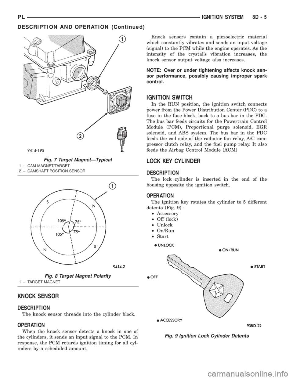
The ignition key rotates the cylinder to 5 different
detents (Fig. 9) :
²Accessory
²Off (lock)
²Unlock
²On/Run
²Start
Fig. 7 Target MagnetÐTypical
1 ± CAM MAGNET/TARGET
2 ± CAMSHAFT POSITION SENSOR
Fig. 8 Target Magnet Polarity
1 ± TARGET MAGNET
Fig. 9 Ignition Lock Cylinder Detents
PLIGNITION SYSTEM 8D - 5
DESCRIPTION AND OPERATION (Continued)
Page 241 of 1285
IGNITION INTERLOCK
OPERATION
All vehicles equipped with automatic transaxles
have an interlock system. The system prevents shift-
ing the vehicle out of Park unless the ignition lock
cylinder is in the Off, Run or Start position. In addi-
tion, the operator cannot rotate the key to the lock
position unless the shifter is in the park position. On
vehicles equipped with floor shift refer to the - Tran-
saxle for Automatic Transmission Shifter/Ignition
Interlock.
REMOVAL AND INSTALLATION
SPARK PLUG SERVICE
Failure to route the cables properly could cause the
radio to reproduce ignition noise, cross ignition of the
spark plugs or short circuit the cables to ground.
REMOVAL
REMOVE CABLES FROM COIL FIRST.
Always remove the spark plug cable by grasping
the top of the spark plug insulator, turning the boot
1/2 turn and pulling straight up in a steady motion.
(1) Remove the spark plug using a quality socket
with a rubber or foam insert.
(2) Inspect the spark plug condition.
INSTALLATION
(1) To avoid cross threading, start the spark plug
into the cylinder head by hand.
(2) Tighten spark plugs to 28 N´m (20 ft. lbs.)
torque.
(3) Install spark plug insulators over spark plugs.
Ensure the top of the spark plug insulator covers the
upper end of the spark plug tube.
Reconnect to coil.
SPARK PLUG CABLE SERVICE
Failure to route the cables properly could cause the
radio to reproduce ignition noise, cross ignition of the
spark plugs or short circuit the cables to ground.
REMOVAL
Remove spark plug cable from coil first.
Always remove the spark plug cable by grasping
the top of the spark plug insulator, turning the boot
1/2 turn and pulling straight up in a steady motion.
INSTALLATION
Install spark plug insulators over spark plugs.
Ensure the top of the spark plug insulator covers the
upper end of the spark plug tube. The connect theother end to coil pack. Be sure that dual plastic clip
holds the cables off of the valve cover.
IGNITION COIL
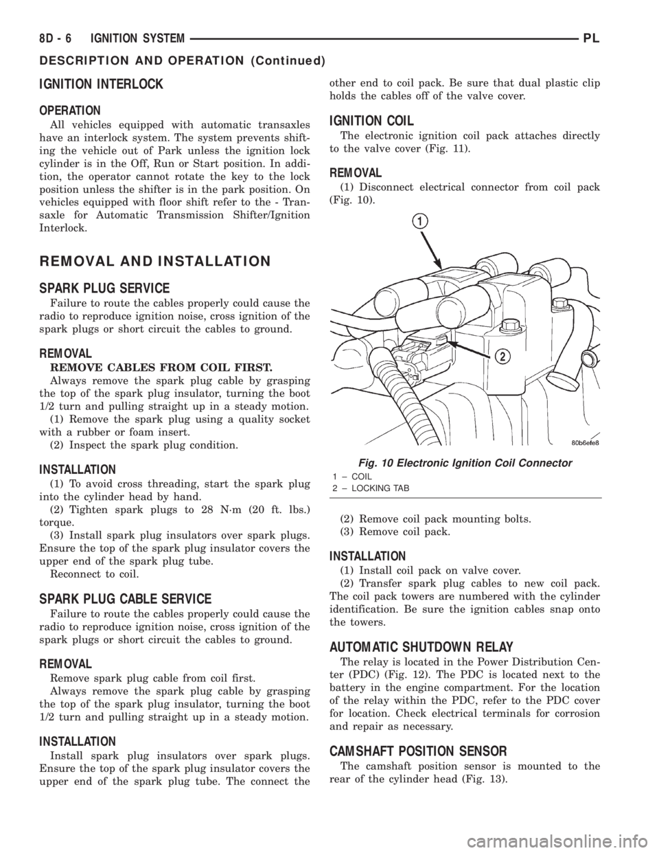
The electronic ignition coil pack attaches directly
to the valve cover (Fig. 11).
REMOVAL
(1) Disconnect electrical connector from coil pack
(Fig. 10).
(2) Remove coil pack mounting bolts.
(3) Remove coil pack.
INSTALLATION
(1) Install coil pack on valve cover.
(2) Transfer spark plug cables to new coil pack.
The coil pack towers are numbered with the cylinder
identification. Be sure the ignition cables snap onto
the towers.
AUTOMATIC SHUTDOWN RELAY
The relay is located in the Power Distribution Cen-
ter (PDC) (Fig. 12). The PDC is located next to the
battery in the engine compartment. For the location
of the relay within the PDC, refer to the PDC cover
for location. Check electrical terminals for corrosion
and repair as necessary.
CAMSHAFT POSITION SENSOR
The camshaft position sensor is mounted to the
rear of the cylinder head (Fig. 13).
Fig. 10 Electronic Ignition Coil Connector
1 ± COIL
2 ± LOCKING TAB
8D - 6 IGNITION SYSTEMPL
DESCRIPTION AND OPERATION (Continued)
Page 243 of 1285
CRANKSHAFT POSITION SENSOR
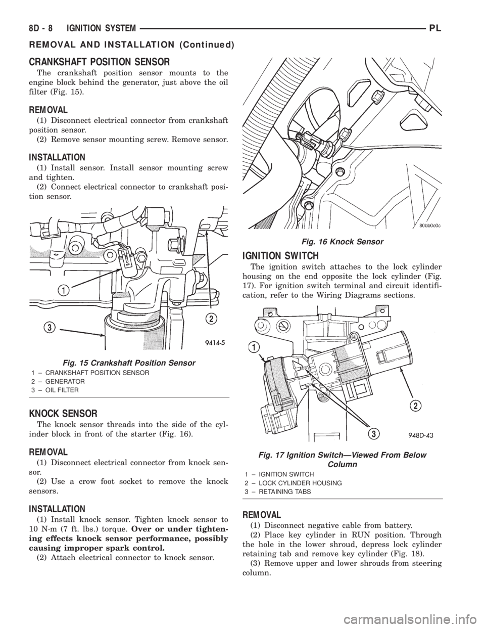
The crankshaft position sensor mounts to the
engine block behind the generator, just above the oil
filter (Fig. 15).
REMOVAL
(1) Disconnect electrical connector from crankshaft
position sensor.
(2) Remove sensor mounting screw. Remove sensor.
INSTALLATION
(1) Install sensor. Install sensor mounting screw
and tighten.
(2) Connect electrical connector to crankshaft posi-
tion sensor.
KNOCK SENSOR
The knock sensor threads into the side of the cyl-
inder block in front of the starter (Fig. 16).
REMOVAL
(1) Disconnect electrical connector from knock sen-
sor.
(2) Use a crow foot socket to remove the knock
sensors.
INSTALLATION
(1) Install knock sensor. Tighten knock sensor to
10 N´m (7 ft. lbs.) torque.Over or under tighten-
ing effects knock sensor performance, possibly
causing improper spark control.
(2) Attach electrical connector to knock sensor.
IGNITION SWITCH
The ignition switch attaches to the lock cylinder
housing on the end opposite the lock cylinder (Fig.
17). For ignition switch terminal and circuit identifi-
cation, refer to the Wiring Diagrams sections.
REMOVAL
(1) Disconnect negative cable from battery.
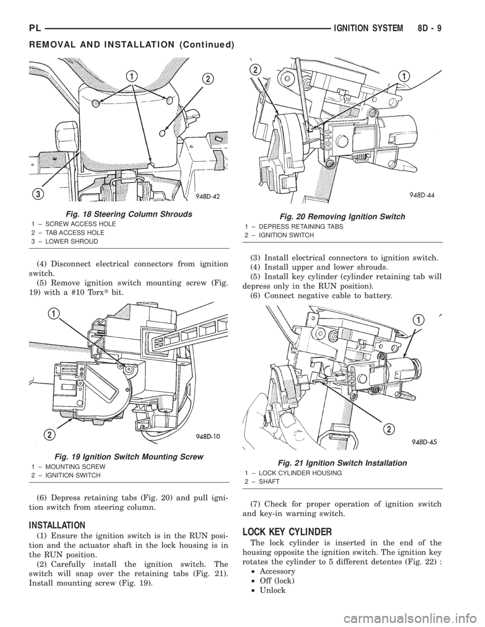
(2) Place key cylinder in RUN position. Through
the hole in the lower shroud, depress lock cylinder
retaining tab and remove key cylinder (Fig. 18).
(3) Remove upper and lower shrouds from steering
column.
Fig. 15 Crankshaft Position Sensor
1 ± CRANKSHAFT POSITION SENSOR
2 ± GENERATOR
3 ± OIL FILTER
Fig. 16 Knock Sensor
Fig. 17 Ignition SwitchÐViewed From Below
Column
1 ± IGNITION SWITCH
2 ± LOCK CYLINDER HOUSING
3 ± RETAINING TABS
8D - 8 IGNITION SYSTEMPL
REMOVAL AND INSTALLATION (Continued)
Page 244 of 1285
(4) Disconnect electrical connectors from ignition
switch.
(5) Remove ignition switch mounting screw (Fig.
19) with a #10 Torxtbit.
(6) Depress retaining tabs (Fig. 20) and pull igni-
tion switch from steering column.
INSTALLATION
(1) Ensure the ignition switch is in the RUN posi-
tion and the actuator shaft in the lock housing is in
the RUN position.
(2) Carefully install the ignition switch. The
switch will snap over the retaining tabs (Fig. 21).
Install mounting screw (Fig. 19).(3) Install electrical connectors to ignition switch.
(4) Install upper and lower shrouds.
(5) Install key cylinder (cylinder retaining tab will
depress only in the RUN position).
(6) Connect negative cable to battery.
(7) Check for proper operation of ignition switch
and key-in warning switch.LOCK KEY CYLINDER
The lock cylinder is inserted in the end of the
housing opposite the ignition switch. The ignition key
rotates the cylinder to 5 different detentes (Fig. 22) :
²Accessory
²Off (lock)
²Unlock
Fig. 18 Steering Column Shrouds
1 ± SCREW ACCESS HOLE
2 ± TAB ACCESS HOLE
3 ± LOWER SHROUD
Fig. 19 Ignition Switch Mounting Screw
1 ± MOUNTING SCREW
2 ± IGNITION SWITCH
Fig. 20 Removing Ignition Switch
1 ± DEPRESS RETAINING TABS
2 ± IGNITION SWITCH
Fig. 21 Ignition Switch Installation
1 ± LOCK CYLINDER HOUSING
2 ± SHAFT
PLIGNITION SYSTEM 8D - 9
REMOVAL AND INSTALLATION (Continued)