2000 DODGE NEON key
[x] Cancel search: keyPage 375 of 1285
memory to determine whether a valid key is in the
ignition lock cylinder.
The Sentry Key transponder cannot be repaired
and, if faulty or damaged, it must be replaced.
SENTRY KEY IMMOBILIZER SYSTEM
INDICATOR LAMP
The Sentry Key Immobilizer System (SKIS) uses
the Vehicle Theft Security System (VTSS) indicator
LED to give an indication when the SKIS is faulty or
when the vehicle has been immobilized due to the
use of an invalid ignition key. The LED is controlled
by the instrument cluster circuitry based upon mes-
sages received from the Sentry Key Immobilizer
Module (SKIM) through the Body Control Module
(BCM) on the Programmable Communication Inter-
face (PCI) bus.
The SKIM sends messages to the instrument clus-
ter, via the BCM, to turn the LED on for about three
seconds when the ignition switch is turned to the ON
position as a bulb test. After completion of the bulb
test, the SKIM sends PCI bus messages to keep the
LED off for a duration of about one second. Then the
SKIM sends messages to the instrument cluster cir-
cuitry to turn the LED on or off based upon the
results of the SKIS self-tests. If the VTSS indicator
LED comes on and stays on after the bulb test, it
indicates that the SKIM has detected a system mal-
function and/or that the SKIS has become inopera-
tive. If the SKIM detects an invalid key when the
ignition switch is turned to the ON position, it sends
messages to the instrument cluster to flash the VTSS
indicator LED.
The SKIM can also send messages to the instru-
ment cluster to flash the LED and to generate a sin-
gle audible chime tone. These functions serve as an
indication to the customer that the SKIS has been
placed in its ªCustomer Learnº programming mode.
See Sentry Key Immobilizer System Transponder
Programming in this group for more information on
the ªCustomer Learnº programming mode.
The VTSS indicator LED uses a replaceable Light
Emitting Diode (LED) on the instrument cluster elec-
tronic circuit board. Refer to Group 8E - Instrument
Panel Systems for Cluster Lamp Removal and Instal-
lation. If the VTSS indicator LED comes on and
stays on after the bulb test function, diagnosis of the
SKIS should be performed with a DRB IIItscan tool
and the proper Body Diagnostic Procedures Manual.
TRIGGERING THE VTSS
After the VTSS is armed, any of the following will
trigger the system:
²Opening any door.
²Opening the hood.
²Removing the trunk lock cylinder.²Turning the ignition to the RUN/START position
with an invalid Sentry Key.
NOTE: The ignition switch can be turned to the
accessory position without triggering the alarm sys-
tem.
DIAGNOSIS AND TESTING
SENTRY KEY IMMOBILIZER SYSTEM
WARNING: ON VEHICLES EQUIPPED WITH AIR-
BAGS, REFER TO GROUP 8M - PASSIVE
RESTRAINT SYSTEMS BEFORE ATTEMPTING ANY
STEERING WHEEL, STEERING COLUMN, OR
INSTRUMENT PANEL COMPONENT DIAGNOSIS OR
SERVICE. FAILURE TO TAKE THE PROPER PRE-
CAUTIONS COULD RESULT IN ACCIDENTAL AIR-
BAG DEPLOYMENT AND POSSIBLE PERSONAL
INJURY.
NOTE: The following tests may not prove conclu-
sive in the diagnosis of this system. The most reli-
able, efficient, and accurate means to diagnose the
Sentry Key Immobilizer System (SKIS) involves the
use of a DRB lllTscan tool and the proper Body
Diagnostic Procedures Manual.
The Sentry Key Immobilizer System (SKIS) and
the Programmable Communication Interface (PCI)
bus network should be diagnosed using a DRB lllt
scan tool. The DRB IIItwill allow confirmation that
the PCI bus is functional, that the Sentry Key Immo-
bilizer Module (SKIM) is placing the proper messages
on the PCI bus, and that the Powertrain Control
Module (PCM) and the instrument cluster are receiv-
ing the PCI bus messages. Refer to the proper Body
Diagnostic Procedures Manual. Refer to Group
8W-Wiring Diagrams for complete circuit descriptions
and diagrams.
(1) Check the fuses in the fuse block. If OK, go to
Step 2. If not OK, repair the shorted circuit or com-
ponent as required and replace the faulty fuse.
(2) Disconnect and isolate the battery negative
cable (Fig. 3). Unplug the wire harness connector at
the SKIM. Check for continuity between the ground
circuit cavity of the SKIM wire harness connector
and a good ground. There should be continuity. If
OK, go to Step 3. If not OK, repair the open circuit to
ground as required.
(3) Connect the battery negative cable. Check for
battery voltage at the fused B(+) circuit cavity of the
SKIM wire harness connector. If OK, go to Step 4. If
not OK, repair the open circuit to the fuse in the fuse
block as required.
8Q - 4 VEHICLE THEFT/SECURITY SYSTEMPL
DESCRIPTION AND OPERATION (Continued)
Page 376 of 1285

(4) Turn the ignition switch to the ON position.
Check for battery voltage at the fused ignition switch
output (run/start) circuit cavity of the SKIM wire
harness connector. If OK, use a DRB IIItscan tool
and the proper Body Diagnostic Procedures Manual
to complete the diagnosis of the SKIS. If not OK,
repair the open circuit to the fuse in the fuse block as
required.
VEHICLE THEFT/SECURITY SYSTEM (VTSS)
To diagnose the Vehicle Theft/Security System
(VTSS), use a DRB IIItscan tool and the proper
Body Diagnostic Procedures Manual.
SERVICE PROCEDURES
SENTRY KEY IMMOBILIZER SYSTEM
INITIALIZATION
The Sentry Key Immobilizer System (SKIS) initial-
ization should be performed following a Sentry Key
Immobilizer Module (SKIM) replacement.
It can be summarized by the following:
(1) Obtain the vehicles unique PIN number
assigned to it's original SKIM from the vehicle
owner, the vehicle's invoice or from Daimler-
Chrysler's Customer Center.
(2) With the DRB IIItscan tool, select ªTheft
Alarm,º ªSKIM,º Miscellaneous.º Select ªSKIM Mod-ule Replacedº function and the DRB llltwill prompt
you through the following steps.
(3) Enter secured access mode using the unique
four digit PIN number.
(4) Program the vehicle's VIN number into the
SKIM's memory.
(5) Program the country code into the SKIM's
memory (U. S.).
(6) Transfer the vehicle's unique Secret Key data
from the PCM. This process will require the SKIM to
be insecured access mode. The PIN number must
be entered into the DRB IIItbefore the SKIM will
entersecured access mode. Oncesecured access
modeis active, the SKIM will remain in that mode
for 60 seconds.
(7) Program all customer keys into the SKIM's
memory. This required that the SKIM be insecured
access modeThe SKIM will immediately exit
secured access modeafter each key is pro-
grammed.
NOTE: SECURED ACCESS MODE is not required to
query the programmed status of the key.
NOTE: If a PCM is replaced, the unique ªSecret
Keyº data must be transferred from the SKIM to the
PCM. This procedure requires the SKIM to be
placed in SECURED ACCESS MODE using the four
digit PIN code.
SENTRY KEY IMMOBILIZER SYSTEM
TRANSPONDER PROGRAMMING
Three programmed Sentry Key transponders are
included with the Sentry Key Immobilizer System
(SKIS) when it is shipped from the factory. The Sen-
try Key Immobilizer Module (SKIM) can be pro-
grammed to recognize up to five additional
transponders, for a total of eight Sentry Keys. The
following ªCustomer Learnº programming procedure
for the programming of additional transponders
requires access to at least two of the valid Sentry
Keys. If two valid Sentry Keys are not available, Sen-
try Key programming will require the use of a DRB
IIItscan tool.
CUSTOMER LEARN PROGRAMMING
(1) Obtain the additional Sentry Key transponder
blank(s) that are to be programmed for the vehicle.
Cut the additional Sentry Key transponder blanks to
match the ignition lock cylinder mechanical key
codes.
(2) Insert one of the two valid Sentry Key tran-
sponders into the ignition switch and turn the igni-
tion switch to the ON position.
Fig. 3 Battery Negative Cable Remove/Install
1 ± NEGATIVE CABLE
2 ± NEGATIVE BATTERY POST
PLVEHICLE THEFT/SECURITY SYSTEM 8Q - 5
DIAGNOSIS AND TESTING (Continued)
Page 377 of 1285
(3) After the ignition switch has been in the ON
position for about three seconds, but no more than
fifteen seconds, cycle the ignition switch back to the
OFF position. Replace the first valid Sentry Key in
the ignition lock cylinder with the second valid Sen-
try Key and turn the ignition switch back to the ON
position. Both operations must be performed within
15 seconds.
(4) About ten seconds after the completion of Step
3, the VTSS indicator LED will start to flash and a
single audible chime tone will sound to indicate that
the system has entered the ªCustomer Learnº pro-
gramming mode.
(5) Within about fifty seconds of entering the ªCus-
tomer Learnº programming mode, turn the ignition
switch to the OFF position, replace the valid Sentry
Key with a blank Sentry Key transponder, and turn
the ignition switch back to the ON position.
(6) About ten seconds after the completion of Step
5, a single audible chime tone will sound and the
VTSS indicator LED will stop flashing and stay on
solid for about three seconds to indicate that the
blank Sentry Key transponder has been successfully
programmed. The SKIS will immediately return to
normal system operation following exit from the
ªCustomer Learnº programming mode.
(7) Go back to Step 2 and repeat this process for
each additional Sentry Key transponder blank to be
programmed.
If any of the above steps is not completed in the
proper sequence, or within the allotted time, the
SKIS will automatically exit the ªCustomer Learnº
programming mode. The SKIS will also automatically
exit the ªCustomer Learnº programming mode if it
sees a non-blank Sentry Key transponder when it
should see a blank, if it has already programmed
eight valid Sentry Keys, or if the ignition switch is
turned to the OFF position for more than about fifty
seconds.
PROGRAMMING BLANK SENTRY KEY
TRANSPONDERS WITH A DRB lllTSCAN TOOL
When programming a blank Sentry Key transpon-
der, the key blank must first be cut to match the
ignition lock cylinder. It will also be necessary to
enter the vehicle's four digit PIN code into the DRB
IIItscan tool to enter the Sentry Key Immobilizer
Module's (SKIM's) secured access mode.
NOTE: Once a Sentry Key is programmed to a par-
ticular vehicle, it cannot be transferred to another
vehicle.
Insert the blank key into the ignition and turn it to
the RUN position. Using the DRB IIItscan tool,
select ªTheft Alarm,º then ªSKIM,º then ªMiscella-
neous.º Select ªProgram New Key.º Enter the fourdigit PIN code using the DRB IIIt. When program-
ming is completed, the SKIM will exit secured access
mode and display the status of the key. One of five
different status messages may be displayed as fol-
lows:
²ªProgramming Successfulº is displayed if SKIM
Sentry Key programming succeeds.
²ªLearned Key in Ignitionº is displayed if the key
in the ignition has already been programmed into
that vehicle's SKIM.
²ª8 Keys Already Learned (At The Maximum)
Programming Not Doneº is displayed if eight keys
have already been programmed into the SKIM. In
this case, if a new key needs to be added due to a
lost or defective key, the ªErase All Keysº function
(requires entering secured access mode) has to be
performed. Then the customer is seven keys plus the
new key MUST be reprogrammed into the SKIM.
²ªProgramming Not Attemptedº is displayed after
an ªErase All Keysº function is executed.
²ªProgramming Key Failedº is displayed if fur-
ther diagnosis is required.
²To learn additional keys, turn the ignition OFF,
remove the learned key, and insert the next new
blank key. Turn ignition to the RUN position and re-
enter the secured access mode function and repeat
the ªProgram New Keyº procedure outlined above.
SWITCHING OPERATING MODES/
CONFIGURING A NEW MODULE
To switch operating modes or to configure a new
module, a DRB IIItscan tool must be used.
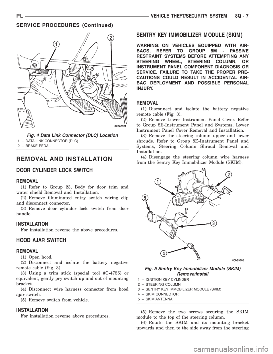
(1) Hook up the DRB IIItscan tool to the Data
Link Connector (DLC) (Fig. 4).
(2) With the key in the ignition, turn the key to
the RUN position.
(3) After the DRB IIItscan tool initialization, per-
form the following:
(a) Select ªTheft Alarm.º
(b) Select ªVTSS.º
(c) Select ªMiscellaneous.º
(4) Once in the ªMiscellaneousº screen:
(a) If you wish to configure a new module, select
ªConfigure Module.º
(b) If you wish to put the module into customer
usage mode, select ªEnable VTSS.º
(c) If you wish to put the module into dealer lot
mode, select ªDealer Lot.º
8Q - 6 VEHICLE THEFT/SECURITY SYSTEMPL
SERVICE PROCEDURES (Continued)
Page 378 of 1285
REMOVAL AND INSTALLATION
DOOR CYLINDER LOCK SWITCH
REMOVAL
(1) Refer to Group 23, Body for door trim and
water shield Removal and Installation.
(2) Remove illuminated entry switch wiring clip
and disconnect connector.
(3) Remove door cylinder lock switch from door
handle.
INSTALLATION
For installation reverse the above procedures.
HOOD AJAR SWITCH
REMOVAL
(1) Open hood.
(2) Disconnect and isolate the battery negative
remote cable (Fig. 3).
(3) Using a trim stick (special tool #C-4755) or
equivalent, gently pry switch up and out of mounting
bracket.
(4) Disconnect wire harness connector from hood
ajar switch.
(5) Remove switch from vehicle.
INSTALLATION
For installation reverse above procedures.
SENTRY KEY IMMOBILIZER MODULE (SKIM)
WARNING: ON VEHICLES EQUIPPED WITH AIR-
BAGS, REFER TO GROUP 8M - PASSIVE
RESTRAINT SYSTEMS BEFORE ATTEMPTING ANY
STEERING WHEEL, STEERING COLUMN, OR
INSTRUMENT PANEL COMPONENT DIAGNOSIS OR
SERVICE. FAILURE TO TAKE THE PROPER PRE-
CAUTIONS COULD RESULT IN ACCIDENTAL AIR-
BAG DEPLOYMENT AND POSSIBLE PERSONAL
INJURY.
REMOVAL
(1) Disconnect and isolate the battery negative
remote cable (Fig. 3).
(2) Remove Lower Instrument Panel Cover. Refer
to Group 8E-Instrument Panel and Systems, Lower
Instrument Panel Cover Removal and Installation.
(3) Remove the steering column upper and lower
shrouds. Refer to Group 8E-Inatrument Panel and
Systems, Steering Column Shroud Removal and
Installation.
(4) Disengage the steering column wire harness
from the Sentry Key Immobilizer Module (SKIM).
(5) Remove the two screws securing the SKIM
module to the top of the steering column.
(6) Rotate the SKIM and its mounting bracket
upwards and then to the side away from the steering
Fig. 4 Data Link Connector (DLC) Location
1 ± DATA LINK CONNECTOR (DLC)
2 ± BRAKE PEDAL
Fig. 5 Sentry Key Immobilizer Module (SKIM)
Remove/Install
1 ± IGNITION KEY CYLINDER
2 ± STEERING COLUMN
3 ± SENTRY KEY IMMOBILIZER MODULE (SKIM)
4 ± SKIM CONNECTOR
5 ± SKIM ANTENNA
PLVEHICLE THEFT/SECURITY SYSTEM 8Q - 7
SERVICE PROCEDURES (Continued)
Page 379 of 1285
column to slide the SKIM antenna ring from around
the ignition switch lock cylinder housing.
(7) Remove the SKIM from the vehicle.
INSTALLATION
(1) For installation, reverse the above procedures.
(2) If the SKIM is replaced with a new unit, a
DRB IIItscan tool MUST be used to initialize the
new SKIM and to program at least two Sentry Key
transponders. Refer to Sentry Key Immobilizer Mod-
ule Initialization in this section.
VEHICLE THEFT/SECURITY SYSTEM DECK LID
SECURITY (KNOCK OUT) SWITCH
The Vehicle Theft Security System (VTSS) Deck
Lid Security (Knock Out) Switch is mounted to the
back of the deck lid lock cylinder.
REMOVAL
(1) Open deck lid.
(2) Disconnect wire connector to switch.
(3) Remove the spring clip retainer.
(4) Pull switch off of deck lid lock cylinder and
remove from vehicle.
INSTALLATION
For installation, reverse the above procedures.
8Q - 8 VEHICLE THEFT/SECURITY SYSTEMPL
REMOVAL AND INSTALLATION (Continued)
Page 390 of 1285
CHIME WARNING/REMINDER SYSTEM
TABLE OF CONTENTS
page page
DESCRIPTION AND OPERATION
INTRODUCTION..........................1
DIAGNOSIS AND TESTING
FASTEN SEAT BELTS......................1
HEADLAMPS LEFT ON.....................1
KEY LEFT IN IGNITION SWITCH.............1CHIME SYSTEM CONDITIONS...............1
REMOVAL AND INSTALLATION
CHIME..................................2
SEAT BELT BUCKLE.......................2
HEADLAMP SWITCH......................2
KEY-IN SWITCH..........................2
DESCRIPTION AND OPERATION
INTRODUCTION
WARNING: ON VEHICLES EQUIPPED WITH AN AIR-
BAG, REFER TO THE AIRBAG PORTION OF THIS
SECTION FOR STEERING WHEEL OR SWITCH
REMOVAL AND INSTALLATION PROCEDURES.
The seat belt reminder system uses both visual
and audible signals. A combined seat belt and key
reminder chime with a red light on the instrument
panel.
The system will always illuminate the seat belt
reminder lamp for four to eight seconds when the
ignition switch is turned to the ON position. The
CHIME will sound during the same time interval if
the driver's seat belt is not fastened. Passenger belts
are not connected to the system.
The chime will activate if the drivers door is
opened and:
²The key is in the ignition switch, with the igni-
tion switch in either the OFF or accessory (ACC)
position.
²The head lamps are ON.
The chime is integral to the instrument cluster.
DIAGNOSIS AND TESTING
FASTEN SEAT BELTS
To test the fasten seat belts function, turn the igni-
tion switch to the ON position with the driver's seat
belt unbuckled and fully retracted. The seat belt
warning lamp should light for four to eight seconds
and the tone should sound three to five times.
If the lamp does not light, check the connection at
the seat belt retractor and the LED in the instru-
ment cluster. Replace as necessary.
HEADLAMPS LEFT ON
These are the conditions that have to be met for
the headlamps on, chime function to work:
²Headlamps ON.
²Driver's door open.
²Key removed from the ignition switch.
Chime should sound until headlamps are turned
off or driver's door is closed.
If these conditions are met and there is still a
problem with the system, replace the instrument
cluster. Refer to Group 8E-Instrument Panel and
Systems, Instrument Cluster Removal and Installa-
tion.
KEY LEFT IN IGNITION SWITCH
To test the key left in ignition function, insert key
into the ignition and open the driver's door. Chime
should sound until key is removed from ignition or
driver's door is closed.
If these conditions are met and there is still a
problem with the system, replace the instrument
cluster. Refer to Group 8E-Instrument Panel and
Systems, Instrument Cluster Removal and Installa-
tion.
CHIME SYSTEM CONDITIONS
NO TONE WHEN IGNITION SWITCH IS TURNED ON
AND DRIVERS SEAT BELT IS UNBUCKLED
(1) Using an ohmmeter, with the seat belt fully
retracted, check for continuity to ground at Pin 25 of
the cluster harness connector. If OK, go to step 2. If
not OK, repair as necessary.
(2) Using voltmeter, check for battery feed at Pin
21 of the cluster harness connector. Check for igni-
tion feed at Pin 15 of the cluster harness connector.
If not OK, repair as necessary.
PLCHIME WARNING/REMINDER SYSTEM 8U - 1
Page 391 of 1285

NO FASTEN SEAT BELT LAMP WHEN IGNITION
SWITCH IS ON
(1) Check for battery feed at cluster harness con-
nector Pin 21.
(2) Check for ignition feed at cluster harness con-
nector Pin 15. Repair as necessary.
NO TONE WHEN HEADLAMPS ARE ON AND
DRIVERS DOOR IS OPEN
(1) Check left door jamb switch for good ground
when drivers door is open.
(2) Check for ground at Pin 10.
(3) Check for battery feed at cluster harness con-
nector Pin 21.
(4) Check for NO voltage at Pin 14. Ignition volt-
age must not be present for the chime to work.
(5) Check headlamp switch.
NO TONE WHEN KEY IS LEFT IN IGNITION AND
DRIVERS DOOR IS OPEN
(1) Check for continuity to ground at Pin 23 of the
cluster harness connector. If OK, go to Step 3. If not
OK, repair as necessary.
(2) Using voltmeter, check for battery feed at Pin
21 of the cluster harness connector. Check for NO
ignition feed at Pin 15 of the cluster harness connec-
tor. If OK, go to Step 3. If not OK, repair as neces-
sary.
(3) Open driver's door and ensure the ignition key
is in the OFF or ACC position. Check for continuity
to ground at Pin 10 of the cluster harness connector.
If ground OK, replace cluster printed circuit board. If
no ground, check key-in switch or door switch wiring
and repair as necessary.
CHIMES CONTINUE WHEN HEADLAMPS ARE
TURNED OFF AND/OR KEY IS REMOVED FROM
IGNITION
Check for ground at Pin 10. If grounded the chime
should activate. Make sure the door is closed, key isin ignition and parking lamps are OFF. If ground is
still present check door switch, key in switch, head-
lamp switch and repair as necessary.
REMOVAL AND INSTALLATION
CHIME
The functions previously performed by the chime
module are now part of the smart cluster. There is no
servicable part of the instrument cluster chime func-
tion. Replacement of the instrument cluster is neces-
sary. Refer to Group 8E-Instrument Panel and
Systems, Instrument Cluster Removal and Installa-
tion.
SEAT BELT BUCKLE
Refer to Group 23-Body, Front Seat Belt Buckle
Removal and Installation.
HEADLAMP SWITCH
Refer to Group 8J-Turn Signal and Hazard Warn-
ing Systems, Multi-Function Switch Removal and
Installation.
KEY-IN SWITCH
The Key-in switch is built into the ignition switch
assembly. Should the Key-in switch require service,
the ignition switch assembly must be replaced. Refer
to Group 8D-Ignition System, Ignition Switch
Removal and Installation.
8U - 2 CHIME WARNING/REMINDER SYSTEMPL
DIAGNOSIS AND TESTING (Continued)
Page 394 of 1285
8W-01 GENERAL INFORMATION
TABLE OF CONTENTS
page page
DESCRIPTION AND OPERATION
CIRCUIT FUNCTIONS......................4
CIRCUIT INFORMATION....................4
CONNECTOR INFORMATION................7
ELECTROSTATIC DISCHARGE (ESD)
SENSITIVE DEVICES.....................8
INTRODUCTION..........................1
NOTES, CAUTIONS, and WARNINGS..........7
SECTION IDENTIFICATION..................5
SPLICE LOCATIONS.......................7
SYMBOLS...............................5
TAKE OUTS..............................8
TERMINOLOGY...........................7
DIAGNOSIS AND TESTING
INTERMITTENT AND POOR CONNECTIONS.....8
TROUBLESHOOTING TESTS................9
TROUBLESHOOTING TOOLS................8TROUBLESHOOTING WIRING PROBLEMS.....10
SERVICE PROCEDURES
CONNECTOR AND TERMINAL
REPLACEMENT........................13
CONNECTOR REPLACEMENT..............12
DIODE REPLACEMENT....................15
TERMINAL REPLACEMENT.................14
TERMINAL/CONNECTOR REPAIR- AUGAT
CONNECTORS.........................12
TERMINAL/CONNECTOR REPAIR-MOLEX
CONNECTORS.........................11
TERMINAL/CONNECTOR REPAIRÐTHOMAS
AND BETTS CONNECTORS...............11
WIRING REPAIR.........................10
SPECIAL TOOLS
WIRING/TERMINAL.......................16
DESCRIPTION AND OPERATION
INTRODUCTION
DiamlerChrysler wiring diagrams are designed to
provide information regarding the vehicles wiring
content. In order to effectively use DiamlerChrysler
wiring diagrams to diagnose and repair a
DiamlerChrysler vehicle, it is important to under-
stand all of their features and characteristics.
Diagrams are arranged such that the power (B+)
side of the circuit is placed near the top of the page,
and the ground (B-) side of the circuit is placed near
the bottom of the page.
All switches, components, and modules are shown
in the at rest position with the doors closed and the
key removed from the ignition.Components are shown two ways. A solid line
around a component indicates that the component is
complete. A dashed line around a component indi-
cates that the component being shown is not com-
plete. Incomplete components have a reference
number to indicate the page where the component is
shown complete.
It is important to realize that no attempt is made
on the diagrams to represent components and wiring
as they appear on the vehicle. For example, a short
piece of wire is treated the same as a long one. In
addition, switches and other components are shown
as simply as possible, with regard to function only.
PL8W - 01 GENERAL INFORMATION 8W - 01 - 1