2000 DODGE NEON battery location
[x] Cancel search: battery locationPage 210 of 1285
BATTERY
TABLE OF CONTENTS
page page
GENERAL INFORMATION
INTRODUCTION..........................1
DESCRIPTION AND OPERATION
BATTERY IGNITION OFF DRAW (IOD).........2
CHARGING TIME REQUIRED................2
DIAGNOSIS AND TESTING
BATTERY BUILT-IN TEST INDICATOR.........3
BATTERY IGNITION OFF DRAW (IOD).........4
BATTERY LOAD TEST......................6
BATTERY OPEN CIRCUIT VOLTAGE...........7
SERVICE PROCEDURES
BATTERY CHARGING......................7CHARGING COMPLETELY DISCHARGED
BATTERY..............................8
VISUAL INSPECTION......................9
REMOVAL AND INSTALLATION
BATTERY...............................10
BATTERY THERMOWRAP..................10
BATTERY TRAY..........................11
SPECIFICATIONS
BATTERY SPECIFICATIONS................11
TORQUE...............................11
GENERAL INFORMATION
INTRODUCTION
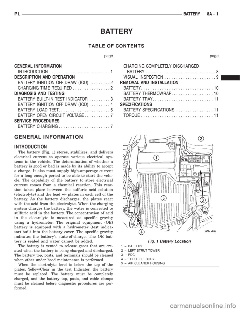
The battery (Fig. 1) stores, stabilizes, and delivers
electrical current to operate various electrical sys-
tems in the vehicle. The determination of whether a
battery is good or bad is made by its ability to accept
a charge. It also must supply high-amperage current
for a long enough period to be able to start the vehi-
cle. The capability of the battery to store electrical
current comes from a chemical reaction. This reac-
tion takes place between the sulfuric acid solution
(electrolyte) and the lead +/- plates in each cell of the
battery. As the battery discharges, the plates react
with the acid from the electrolyte. When the charging
system charges the battery, the water is converted to
sulfuric acid in the battery. The concentration of acid
in the electrolyte is measured as specific gravity
using a hydrometer. The original equipment (OE)
battery is equipped with a hydrometer (test indica-
tor) built into the battery cover. The specific gravity
indicates the battery's state-of-charge. The OE bat-
tery is sealed and water cannot be added.
The battery is vented to release gases that are cre-
ated when the battery is being charged and discharged.
The battery top, posts, and terminals should be cleaned
when other under hood maintenance is performed.
When the electrolyte level is below the top of the
plates, Yellow/Clear in the test Indicator, the battery
must be replaced. The battery must be completely
charged, and the battery top, posts, and cable clamps
must be cleaned before diagnostic procedures are per-
formed.
Fig. 1 Battery Location
1 ± BATTERY
2 ± LEFT STRUT TOWER
3 ± PDC
4 ± THROTTLE BODY
5 ± AIR CLEANER HOUSING
PLBATTERY 8A - 1
Page 223 of 1285
DIAGNOSIS AND TESTING
CONTROL CIRCUIT
The starter control circuit has:
²Starter solenoid
²Starter relay
²Park/Neutral Starting and Back-Up Lamp
Switch with automatic transmissions
²Clutch Interlock/Upstop Switch with manual
transmissions
²Ignition switch
²Battery
²All related wiring and connections
²Double Start Override algorithm located in the
PCM
CAUTION: Before performing any starter tests, the
ignition and fuel systems must be disabled.
²To disable ignition and fuel systems, disconnect
the Automatic Shutdown Relay (ASD). The ASD relay
is located in the in the Power Distribution Center
(PDC). Refer to the PDC cover for the proper relay
location.
STARTER SOLENOID
WARNING: CHECK TO ENSURE THAT THE TRANS-
MISSION IS IN THE PARK POSITION WITH THE
PARKING BRAKE APPLIED
(1) Verify battery condition. Battery must be in
good condition with a full charge before performing
any starter tests. Refer to Battery Tests.
(2) Perform Starter Solenoid test BEFORE per-
forming the starter relay test.
(3) Raise the vehicle.
(4) Perform a visual inspection of the starter/
starter solenoid for corrosion, loose connections or
faulty wiring.
(5) Lower the vehicle.
(6) Locate and remove the starter relay from the
Power Distribution Center (PDC). Refer to the PDC
label for relay identification and location.
(7) Connect a starter switch or a jumper wire
between the remote battery positive post and termi-
nal 87 of the starter relay connector.
(a) If engine cranks, starter motor and starter
solenoid is good. Go to the Starter Relay Test.(b) If engine does not crank or solenoid chatters,
check wiring and connectors from starter relay to
starter solenoid for loose or corroded connections.
Check for corroded connections at starter termi-
nals.
(c) Repeat test. If engine still fails to crank prop-
erly, trouble is within starter or starter mounted
solenoid, and replace starter.
STARTER RELAY
WARNING: CHECK TO ENSURE THAT THE TRANS-
MISSION IS IN THE PARK POSITION WITH THE
PARKING BRAKE APPLIED.
RELAY TEST
The starter relay is located in the Power Distribu-
tion Center (PDC) in the engine compartment. Refer
to the PDC label for relay identification and location.
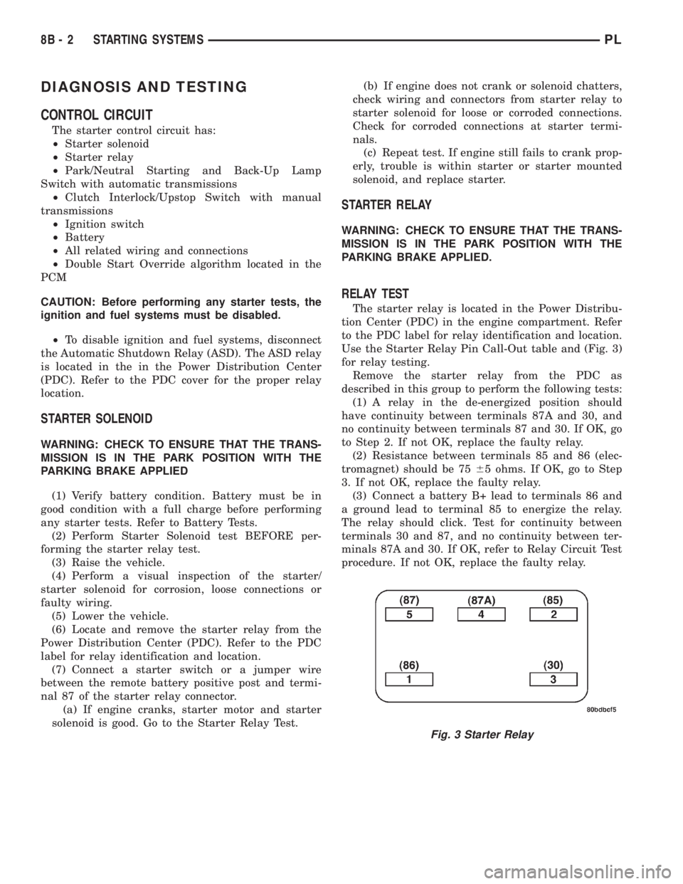
Use the Starter Relay Pin Call-Out table and (Fig. 3)
for relay testing.
Remove the starter relay from the PDC as
described in this group to perform the following tests:
(1) A relay in the de-energized position should
have continuity between terminals 87A and 30, and
no continuity between terminals 87 and 30. If OK, go
to Step 2. If not OK, replace the faulty relay.
(2) Resistance between terminals 85 and 86 (elec-
tromagnet) should be 7565 ohms. If OK, go to Step
3. If not OK, replace the faulty relay.
(3) Connect a battery B+ lead to terminals 86 and
a ground lead to terminal 85 to energize the relay.
The relay should click. Test for continuity between
terminals 30 and 87, and no continuity between ter-
minals 87A and 30. If OK, refer to Relay Circuit Test
procedure. If not OK, replace the faulty relay.
Fig. 3 Starter Relay
8B - 2 STARTING SYSTEMSPL
Page 224 of 1285
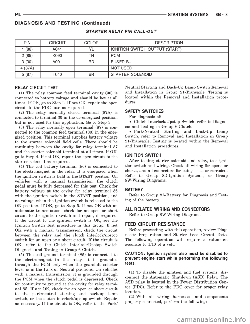
STARTER RELAY PIN CALL-OUT
PIN CIRCUIT COLOR DESCRIPTION
1 (86) A041 YL IGNITION SWITCH OUTPUT (START)
2 (85) K090 TN PCM
3 (30) A001 RD FUSED B+
4 (87A) NOT USED
5 (87) T040 BR STARTER SOLENOID
RELAY CIRCUIT TEST
(1) The relay common feed terminal cavity (30) is
connected to battery voltage and should be hot at all
times. If OK, go to Step 2. If not OK, repair the open
circuit to the PDC fuse as required.
(2) The relay normally closed terminal (87A) is
connected to terminal 30 in the de-energized position,
but is not used for this application. Go to Step 3.
(3) The relay normally open terminal (87) is con-
nected to the common feed terminal (30) in the ener-
gized position. This terminal supplies battery voltage
to the starter solenoid field coils. There should be
continuity between the cavity for relay terminal 87
and the starter solenoid terminal at all times. If OK,
go to Step 4. If not OK, repair the open circuit to the
starter solenoid as required.
(4) The coil battery terminal (86) is connected to
the electromagnet in the relay. It is energized when
the ignition switch is held in the START position. On
vehicles with a manual transmission, the clutch
pedal must be fully depressed for this test. Check for
battery voltage at the cavity for relay terminal 86
with the ignition switch in the START position, and
no voltage when the ignition switch is released to the
ON position. If OK, go to Step 5. If not OK with an
automatic transmission, check for an open or short
circuit to the ignition switch and repair, if required.
If the circuit to the ignition switch is OK, see the
Ignition Switch Test procedure in this group. If not
OK with a manual transmission, check the circuit
between the relay and the clutch interlock/upstop
switch for an open or a short circuit. If the circuit is
OK, refer to the Clutch Interlock/Upstop Switch
Diagnosis and Testing in Group 6-Clutch.
(5) The coil ground terminal (85) is connected to
the electromagnet in the relay. It is grounded
through the PCM only when the gearshift selector
lever is in the Park or Neutral positions. On vehicles
with a manual transmission, it is grounded through
the PCM when the clutch pedal is depressed. Check
for continuity to ground at the cavity for relay termi-
nal 85. If not OK, check for an open or short circuit
to the park/neutral starting and back-up lamp
switch, or the clutch interlock/upstop switch. Repair,
as necessary. If the circuit is OK, refer to the Park/Neutral Starting and Back-Up Lamp Switch Removal
and Installation in Group 21-Transaxle. Testing is
located within the Removal and Installation proce-
dures.
SAFETY SWITCHES
For diagnosis of:
²Clutch Interlock/Upstop Switch, refer to Diagno-
sis and Testing in Group 6-Clutch.
²Park/Neutral Starting and Back-Up Lamp
Switch, refer to Removal and Installation in Group
21-Transaxle. Testing is located within the Removal
and Installation procedures.
IGNITION SWITCH
After testing starter solenoid and relay, test igni-
tion switch and wiring. Check all wiring for opens or
shorts, and all connectors for being loose or corroded.
Refer to Group 8D-Ignition Systems, or Group
8W-Wiring Diagrams.
BATTERY
Refer to Group 8A-Battery for Diagnosis and Test-
ing of the battery.
ALL RELATED WIRING AND CONNECTORS
Refer to Group 8W-Wiring Diagrams.
FEED CIRCUIT RESISTANCE
Before proceeding with this operation, review Diag-
nostic Preparation and Starter Feed Circuit Tests.
The following operation will require a voltmeter,
accurate to 1/10 of a volt.
CAUTION: Ignition system also must be disabled to
prevent engine start while performing the following
tests.
(1) To disable the ignition and fuel systems, dis-
connect the Automatic Shutdown (ASD) Relay. The
ASD relay is located in the Power Distribution Cen-
ter (PDC). Refer to the PDC cover for proper relay
location.
(2) With all wiring harnesses and components
properly connected, perform the following:
PLSTARTING SYSTEMS 8B - 3
DIAGNOSIS AND TESTING (Continued)
Page 226 of 1285
FEED CIRCUIT
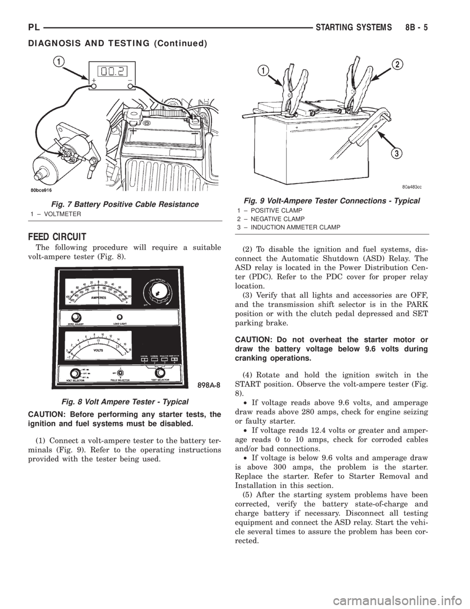
The following procedure will require a suitable
volt-ampere tester (Fig. 8).
CAUTION: Before performing any starter tests, the
ignition and fuel systems must be disabled.
(1) Connect a volt-ampere tester to the battery ter-
minals (Fig. 9). Refer to the operating instructions
provided with the tester being used.(2) To disable the ignition and fuel systems, dis-
connect the Automatic Shutdown (ASD) Relay. The
ASD relay is located in the Power Distribution Cen-
ter (PDC). Refer to the PDC cover for proper relay
location.
(3) Verify that all lights and accessories are OFF,
and the transmission shift selector is in the PARK
position or with the clutch pedal depressed and SET
parking brake.
CAUTION: Do not overheat the starter motor or
draw the battery voltage below 9.6 volts during
cranking operations.
(4) Rotate and hold the ignition switch in the
START position. Observe the volt-ampere tester (Fig.
8).
²If voltage reads above 9.6 volts, and amperage
draw reads above 280 amps, check for engine seizing
or faulty starter.
²If voltage reads 12.4 volts or greater and amper-
age reads 0 to 10 amps, check for corroded cables
and/or bad connections.
²If voltage is below 9.6 volts and amperage draw
is above 300 amps, the problem is the starter.
Replace the starter. Refer to Starter Removal and
Installation in this section.
(5) After the starting system problems have been
corrected, verify the battery state-of-charge and
charge battery if necessary. Disconnect all testing
equipment and connect the ASD relay. Start the vehi-
cle several times to assure the problem has been cor-
rected.
Fig. 7 Battery Positive Cable Resistance
1 ± VOLTMETER
Fig. 8 Volt Ampere Tester - Typical
Fig. 9 Volt-Ampere Tester Connections - Typical
1 ± POSITIVE CLAMP
2 ± NEGATIVE CLAMP
3 ± INDUCTION AMMETER CLAMP
PLSTARTING SYSTEMS 8B - 5
DIAGNOSIS AND TESTING (Continued)
Page 229 of 1285
REMOVAL AND INSTALLATION
SAFETY SWITCHES
For Removal and Installation of:
²Clutch Interlock/Upstop Switch, refer to
Removal and Installation in Group 6-Clutch.
²Park/Neutral Starting and Back-Up Lamp
Switch, refer to Removal and Installation in Group
21-Transaxle.
STARTER MOTOR
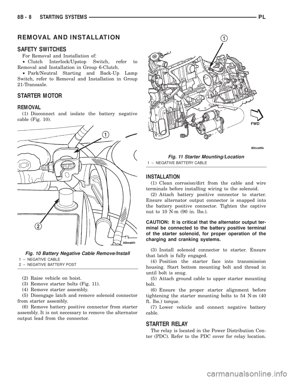
REMOVAL
(1) Disconnect and isolate the battery negative
cable (Fig. 10).
(2) Raise vehicle on hoist.
(3) Remove starter bolts (Fig. 11).
(4) Remove starter assembly.
(5) Disengage latch and remove solenoid connector
from starter assembly.
(6) Remove battery positive connector from starter
assembly. It is not necessary to remove the alternator
output lead from the connector.
INSTALLATION
(1) Clean corrosion/dirt from the cable and wire
terminals before installing wiring to the solenoid.
(2) Attach battery positive connector to starter.
Ensure alternator output connector is snapped into
the battery positive connector. Tighten the captive
nut to 10 N´m (90 in. lbs.).
CAUTION: It is critical that the alternator output ter-
minal be connected to the battery positive terminal
of the starter solenoid, for proper operation of the
charging and cranking systems.
(3) Install solenoid connector to starter. Ensure
that latch is fully engaged.
(4) Position the starter face into transmission
housing. Start bottom mounting bolt and thread in
until bolt is snug.
(5) Attach ground cable to upper starter mounting
bolt.
(6) Ensure the proper starter alignment before
tightening the starter mounting bolts to 54 N´m (40
ft. lbs.) torque.
(7) Lower vehicle and connect negative battery
cable.
STARTER RELAY
The relay is located in the Power Distribution Cen-
ter (PDC). Refer to the PDC cover for relay location.
Fig. 10 Battery Negative Cable Remove/Install
1 ± NEGATIVE CABLE
2 ± NEGATIVE BATTERY POST
Fig. 11 Starter Mounting/Location
1 ± NEGATIVE BATTERY CABLE
8B - 8 STARTING SYSTEMSPL
Page 237 of 1285

Loose cable connections will corrode, increase resis-
tance and permit water to enter the coil towers.
These conditions can cause ignition malfunction.
Plastic clips in various locations protect the cables
from damage. When the cables are replaced the clips
must be used to prevent damage to the cables, and
should be rotated about 30É below the horizontal.
ELECTRONIC IGNITION COILS
DESCRIPTION
The coil pack consists of 2 coils molded together.
The coil pack is mounted on the valve cover (Fig. 2).
OPERATION
WARNING: THE DIRECT IGNITION SYSTEM GEN-
ERATES APPROXIMATELY 40,000 VOLTS. PER-
SONAL INJURY COULD RESULT FROM CONTACT
WITH THIS SYSTEM.
High tension leads route to each cylinder from the
coil. The coil fires two spark plugs every power
stroke. One plug is the cylinder under compression,
the other cylinder fires on the exhaust stroke. Coil
number one fires cylinders 1 and 4. Coil number two
fires cylinders 2 and 3. The PCM determines which
of the coils to charge and fire at the correct time.
The Auto Shutdown (ASD) relay provides battery
voltage to the ignition coil. The PCM provides a
ground contact (circuit) for energizing the coil. When
the PCM breaks the contact, the energy in the coil
primary transfers to the secondary causing thespark. The PCM will de-energize the ASD relay if it
does not receive the crankshaft position sensor and
camshaft position sensor inputs. Refer to Auto Shut-
down (ASD) RelayÐPCM Output, in this section for
relay operation.
AUTOMATIC SHUTDOWN RELAY
DESCRIPTION
The ASD relay is located in the PDC (Fig. 3). The
inside top of the PDC cover has label showing relay
and fuse identification.
Fig. 1 Checking Spark Plug Electrode Gap
1 ± TAPER GAUGE
Fig. 2 Ignition Coil Pack
1 ± IGNITION COILS
2 ± SPARK PLUG CABLE
3 ± SPARK PLUG INSULATOR
Fig. 3 Power Distribution Center (PDC)
8D - 2 IGNITION SYSTEMPL
DESCRIPTION AND OPERATION (Continued)
Page 241 of 1285
IGNITION INTERLOCK
OPERATION
All vehicles equipped with automatic transaxles
have an interlock system. The system prevents shift-
ing the vehicle out of Park unless the ignition lock
cylinder is in the Off, Run or Start position. In addi-
tion, the operator cannot rotate the key to the lock
position unless the shifter is in the park position. On
vehicles equipped with floor shift refer to the - Tran-
saxle for Automatic Transmission Shifter/Ignition
Interlock.
REMOVAL AND INSTALLATION
SPARK PLUG SERVICE
Failure to route the cables properly could cause the
radio to reproduce ignition noise, cross ignition of the
spark plugs or short circuit the cables to ground.
REMOVAL
REMOVE CABLES FROM COIL FIRST.
Always remove the spark plug cable by grasping
the top of the spark plug insulator, turning the boot
1/2 turn and pulling straight up in a steady motion.
(1) Remove the spark plug using a quality socket
with a rubber or foam insert.
(2) Inspect the spark plug condition.
INSTALLATION
(1) To avoid cross threading, start the spark plug
into the cylinder head by hand.
(2) Tighten spark plugs to 28 N´m (20 ft. lbs.)
torque.
(3) Install spark plug insulators over spark plugs.
Ensure the top of the spark plug insulator covers the
upper end of the spark plug tube.
Reconnect to coil.
SPARK PLUG CABLE SERVICE
Failure to route the cables properly could cause the
radio to reproduce ignition noise, cross ignition of the
spark plugs or short circuit the cables to ground.
REMOVAL
Remove spark plug cable from coil first.
Always remove the spark plug cable by grasping
the top of the spark plug insulator, turning the boot
1/2 turn and pulling straight up in a steady motion.
INSTALLATION
Install spark plug insulators over spark plugs.
Ensure the top of the spark plug insulator covers the
upper end of the spark plug tube. The connect theother end to coil pack. Be sure that dual plastic clip
holds the cables off of the valve cover.
IGNITION COIL
The electronic ignition coil pack attaches directly
to the valve cover (Fig. 11).
REMOVAL
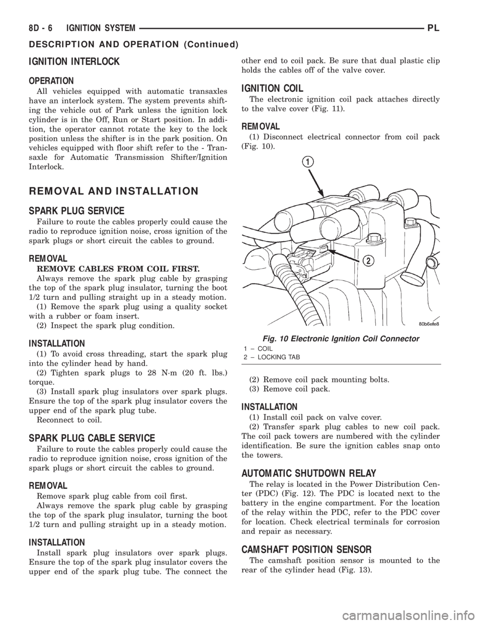
(1) Disconnect electrical connector from coil pack
(Fig. 10).
(2) Remove coil pack mounting bolts.
(3) Remove coil pack.
INSTALLATION
(1) Install coil pack on valve cover.
(2) Transfer spark plug cables to new coil pack.
The coil pack towers are numbered with the cylinder
identification. Be sure the ignition cables snap onto
the towers.
AUTOMATIC SHUTDOWN RELAY
The relay is located in the Power Distribution Cen-
ter (PDC) (Fig. 12). The PDC is located next to the
battery in the engine compartment. For the location
of the relay within the PDC, refer to the PDC cover
for location. Check electrical terminals for corrosion
and repair as necessary.
CAMSHAFT POSITION SENSOR
The camshaft position sensor is mounted to the
rear of the cylinder head (Fig. 13).
Fig. 10 Electronic Ignition Coil Connector
1 ± COIL
2 ± LOCKING TAB
8D - 6 IGNITION SYSTEMPL
DESCRIPTION AND OPERATION (Continued)
Page 253 of 1285
(6) Set base aside and remove base mount ring.
INSTALLATION
(1) Position mount ring to the instrument panel
and feed the wires through ring. Index the cap and
the mount ring with the index tab at 9 o'clock to the
key in the instrument panel. Install the ring.
(2) Connect wires to base. Orient base alignment
rib at 11 o'clock to mate the groove in mount ring at
the same location
(3) Push base into the bezel till it locks.
(4) Install cigar lighter cap and check operation of
element.
GLOVE BOX DOOR/BIN
REMOVAL
(1) Open front passenger door.
(2) Remove three glove box door hinge screws.
(3) Open glove box and remove assembly from
vehicle.
(4) Remove eight screws retaining glove box door
to bin assembly.
(5) Separate glove box door from bin and remove.
INSTALLATION
For installation, reverse the above procedures.
GLOVE BOX DOOR/BIN
REMOVAL
(1) Open front passenger door.
(2) Remove three glove box door hinge screws.
(3) Open glove box and remove assembly from
vehicle.
(4) Remove eight screws retaining glove box door
to bin assembly.(5) Separate glove box door from bin and remove.
INSTALLATION
For installation, reverse the above procedures.
GLOVE BOX SWITCH/LAMP
REMOVAL
(1) Disconnect and isolate the battery negative
cable (Fig. 6).
(2) Open the glove box and push the glove box
sides inward allowing the door bumpers to clear and
the box to tip forward.
(3) Reach inside the opening and squeeze the
lamp/switch retainers until they are disengage.
(4) Pull the switch/lamp rearward and remove it.
Replace the lamp. To replace the switch disconnect
wire and replace the switch.
INSTALLATION
For installation, reverse the above procedures.
INSTRUMENT CLUSTER
CAUTION: The Instrument Cluster MUST be stored
in a face up position or damage will occur to the
gauge operation.
REMOVAL
(1) Disconnect and isolate the battery negative
cable (Fig. 6).
(2) Remove both left and right A-Pillar trim covers.
(3) Remove the instrument panel top cover.
(4) Remove cluster bezel.
(5) Remove the four screws attaching cluster hous-
ing to the base panel.
(6) Pull the cluster rearward to disconnect from
base panel.
(7) Remove the cluster assembly.
INSTALLATION
For installation, reverse the above procedures.
INSTRUMENT CLUSTER BEZEL
REMOVAL
(1) Remove instrument panel top cover. Refer to
Instrument Panel Top Cover Removal and Installa-
tion in this section.
(2) Using a trim stick (special tool #C-4755), gently
pry up on the cluster bezel and remove from vehicle.
INSTALLATION
For installation, reverse the above procedures.
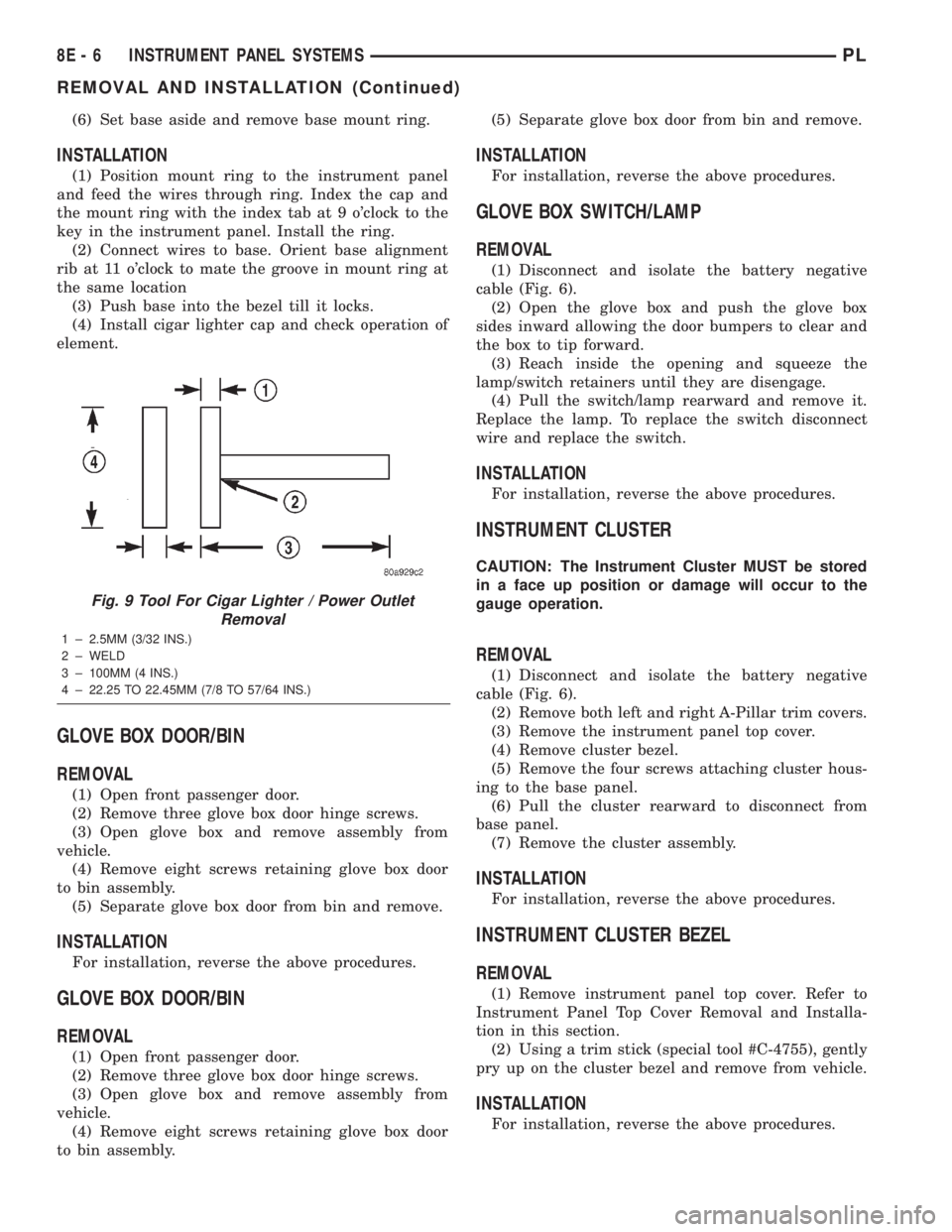
Fig. 9 Tool For Cigar Lighter / Power Outlet
Removal
1 ± 2.5MM (3/32 INS.)
2 ± WELD
3 ± 100MM (4 INS.)
4 ± 22.25 TO 22.45MM (7/8 TO 57/64 INS.)
8E - 6 INSTRUMENT PANEL SYSTEMSPL
REMOVAL AND INSTALLATION (Continued)