2000 DODGE NEON battery location
[x] Cancel search: battery locationPage 770 of 1285
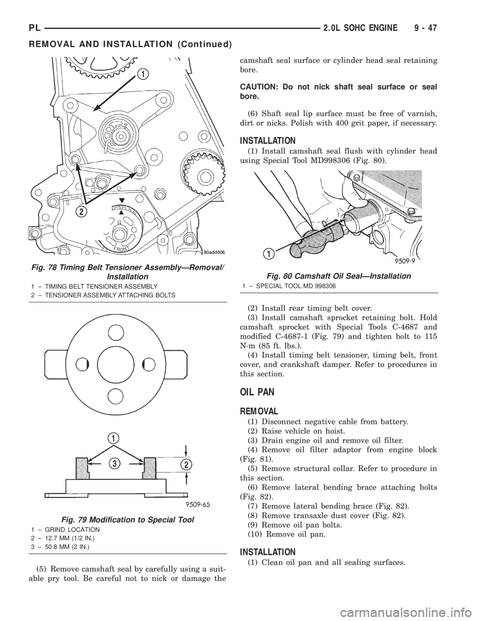
(5) Remove camshaft seal by carefully using a suit-
able pry tool. Be careful not to nick or damage thecamshaft seal surface or cylinder head seal retaining
bore.
CAUTION: Do not nick shaft seal surface or seal
bore.
(6) Shaft seal lip surface must be free of varnish,
dirt or nicks. Polish with 400 grit paper, if necessary.
INSTALLATION
(1) Install camshaft seal flush with cylinder head
using Special Tool MD998306 (Fig. 80).
(2) Install rear timing belt cover.
(3) Install camshaft sprocket retaining bolt. Hold
camshaft sprocket with Special Tools C-4687 and
modified C-4687-1 (Fig. 79) and tighten bolt to 115
N´m (85 ft. lbs.).
(4) Install timing belt tensioner, timing belt, front
cover, and crankshaft damper. Refer to procedures in
this section.
OIL PAN
REMOVAL
(1) Disconnect negative cable from battery.
(2) Raise vehicle on hoist.
(3) Drain engine oil and remove oil filter.
(4) Remove oil filter adaptor from engine block
(Fig. 81).
(5) Remove structural collar. Refer to procedure in
this section.
(6) Remove lateral bending brace attaching bolts
(Fig. 82).
(7) Remove lateral bending brace (Fig. 82).
(8) Remove transaxle dust cover (Fig. 82).
(9) Remove oil pan bolts.
(10) Remove oil pan.
INSTALLATION
(1) Clean oil pan and all sealing surfaces.
Fig. 78 Timing Belt Tensioner AssemblyÐRemoval/
Installation
1 ± TIMING BELT TENSIONER ASSEMBLY
2 ± TENSIONER ASSEMBLY ATTACHING BOLTS
Fig. 79 Modification to Special Tool
1 ± GRIND LOCATION
2 ± 12.7 MM (1/2 IN.)
3 ± 50.8 MM (2 IN.)
Fig. 80 Camshaft Oil SealÐInstallation
1 ± SPECIAL TOOL MD 998306
PL2.0L SOHC ENGINE 9 - 47
REMOVAL AND INSTALLATION (Continued)
Page 833 of 1285

REMOVAL AND INSTALLATION
AUTOMATIC SHUTDOWN RELAY
The relay is located in the Power Distribution Cen-
ter (PDC) (Fig. 12). The PDC is located next to the
battery in the engine compartment. For the location
of the relay within the PDC, refer to the PDC cover
for location. Check electrical terminals for corrosion
and repair as necessary.
FUEL PUMP RELAY
The fuel pump relay is located in the PDC. The
inside top of the PDC cover has a label showing relay
and fuse location.
FUEL PUMP MODULE
REMOVAL
WARNING: RELEASE FUEL SYSTEM PRESSURE
BEFORE SERVICING FUEL SYSTEM COMPONENTS.
SERVICE VEHICLES IN WELL VENTILATED AREAS
AND AVOID IGNITION SOURCES. NEVER SMOKE
WHILE SERVICING THE VEHICLE.
(1) Drain the fuel. Refer to Draining Fuel Tank in
the Fuel Tank section of this group.
WARNING: THE FUEL RESERVOIR OF THE FUEL
PUMP MODULE DOES NOT EMPTY OUT WHEN THE
TANK IS DRAINED. THE FUEL IN THE RESERVOIR
WILL SPILL OUT WHEN THE MODULE IS
REMOVED.
(2) Remove fuel tank, refer to the Fuel Tank
removal/installation section.
(3) Lower tank.(4) Use Special Tool 6856 to remove fuel pump
module locknut (Fig. 15).
(5) Remove fuel pump and O-ring seal from tank.
Discard old seal.
INSTALLATION
(1) Wipe seal area of tank clean and place a new
seal in position in the tank opening.
(2) Position fuel pump in the tank. Make sure the
alignment tab on the underside of the fuel pump
module flange sits in the notch on the fuel tank (Fig.
14).
(3) Position the locknut over the fuel pump mod-
ule.
Fig. 12 Power Distribution Center (PDC)
Fig. 13 Fuel Pump Module Removal
1 ± FUEL FILTER/PRESSURE REGULATOR
2 ± FUEL LINE
3 ± LOCKNUT
Fig. 14 Alignment Tab
14 - 12 FUEL SYSTEMPL
Page 859 of 1285
Like all Hall-effect sensors, the electronics of the
sensor needs a power source. This power source is
provided by the PCM. It is the same 8 volt power
supply that is used by the CKP and CMP sensors.
The vehicle speed sensor generates 8 pulses per
sensor revolution. This signal, in conjunction with a
closed throttle signal from the throttle position sen-
sor, indicates a closed throttle deceleration to the
PCM. Under deceleration conditions, the PCM
adjusts the Idle Air Control (IAC) motor to maintain
a desired MAP value.
When the vehicle is stopped at idle, a closed throt-
tle signal is received by the PCM (but a speed sensor
signal is not received). Under idle conditions, the
PCM adjusts the IAC motor to maintain a desired
engine speed.
AIR CONDITIONING CLUTCH RELAYÐPCM
OUTPUT
DESCRIPTION
The air conditioning clutch relay is located in the
PDC. The inside top of the PDC cover has a label
showing relay and fuse location.
OPERATION
The PCM controls the air conditioning clutch relay
ground circuit. The A/C clutch relay coil side contains
a 10 amp fuse between the buss bar in the Power
Distribution Center (PDC) and the relay. The power
side of this relay is fused with a 40 amp fuse. When
the PCM receives an air conditioning input, it
grounds the A/C compressor clutch relay and the
radiator fan relay.
When the PCM senses low idle speeds or wide open
throttle through the throttle position sensor, it
removes the ground for the A/C compressor clutch
relay. When the relay de-energizes, the contacts open
preventing air conditioning clutch engagement. Also,
if the PCM senses a part throttle launch condition, it
disables the A/C compressor clutch for several sec-
onds.
AUTOMATIC SHUTDOWN RELAYÐPCM
OUTPUT
DESCRIPTION
The ASD relay is located in the PDC. The inside
top of the PDC cover has a label showing relay and
fuse location.
OPERATION
The automatic shutdown (ASD) relay supplies bat-
tery voltage to the fuel injectors, electronic ignition
coil and the heating elements in the oxygen sensors
generator field and PCM sense circuit.A buss bar in the power distribution center (PDC)
supplies voltage to the solenoid side and contact side
of the relay. The ASD relay power circuit contains a
fuse between the buss bar in the PDC and the relay.
The fuse also protects the power circuit for the fuel
pump relay and pump. The fuse is located in the
PDC. Refer to the Wiring Diagrams for circuit infor-
mation.
The PCM controls the relay by switching the
ground path for the solenoid side of the relay on and
off. The PCM turns the ground path off when the
ignition switch is in the Off position unless the 02
Heater Monitor test is being run. When the ignition
switch is in the On or Crank position, the PCM mon-
itors the crankshaft position sensor and camshaft
position sensor signals to determine engine speed
and ignition timing (coil dwell). If the PCM does not
receive the crankshaft position sensor and camshaft
position sensor signals when the ignition switch is in
the Run position, it will de-energize the ASD relay.
CHARGING SYSTEM INDICATOR LAMPÐPCM
OUTPUT
OPERATION
The PCM turns the instrument panel Charging
System Lamp on. Refer to the Charging system sec-
tion information.
FUEL PUMP RELAYÐPCM OUTPUT
DESCRIPTION
The fuel pump relay is located in the PDC. The
inside top of the PDC cover has a label showing relay
and fuse location.
OPERATION
The fuel pump relay supplies battery voltage to the
fuel pump. A buss bar in the Power Distribution Cen-
ter (PDC) supplies voltage to the solenoid side and
contact side of the relay. The fuel pump relay power
circuit contains a fuse between the buss bar in the
PDC and the relay. The fuse also protects the power
circuit for the Automatic Shutdown (ASD) relay. The
fuse is located in the PDC. Refer to the Wiring Dia-
grams for circuit information.
The PCM controls the fuel pump relay by switch-
ing the ground path for the solenoid side of the relay
on and off. The PCM turns the ground path off when
the ignition switch is in the Off position. When the
ignition switch is in the On position, the PCM ener-
gizes the fuel pump. If the crankshaft position sensor
does not detect engine rotation, the PCM de-ener-
gizes the relay after approximately one second.
14 - 38 FUEL SYSTEMPL
DESCRIPTION AND OPERATION (Continued)
Page 885 of 1285

(3) Install the hose clamp on the power steering
cooler fluid hose past the bead formed into the steel
fitting and secure in place.
(4) Install the two screws attaching the cooler to
the front suspension crossmember. Tighten the cooler
attaching screws to a torque of 10 N´m (90 in. lbs.).
(5) Install the power steering fluid return hose on
the power steering fluid cooler tube. Install the hose
clamp on the power steering return hose securing it
to the power steering cooler. Be sure the hose clamp
is installed on the return hose past the bead on the
end of the cooler tube.
(6) Lower the vehicle.
(7) Perform the POWER STEERING PUMP INI-
TIAL OPERATION service procedure which can be
found in the POWER STEERING PUMP section of
this group to properly fill and bleed the power steer-
ing system.
(8) Check for leaks at all connections.
POWER STEERING FLUID PRESSURE SWITCH
NOTE: Before proceeding with this removal and
installation procedure, review SERVICE WARNINGS
AND CAUTIONS at the beginning of REMOVAL AND
INSTALLATION in this section.
REMOVAL
(1) Disconnect negative battery cable from the neg-
ative post of the battery. Be sure cable is isolated
from negative post on battery.(2) Raise the vehicle. Refer to HOISTING in the
LUBRICATION AND MAINTENANCE group in this
service manual for the correct lifting procedure.
(3) Locate the power steering fluid pressure switch
on the back side of the power steering gear (Fig. 9).
(4) Remove the vehicle wiring harness connector
from the power steering fluid pressure switch.
NOTE: When removing and installing the power
steering pressure switch, use a 7/8 inch deep well
socket. The deep well socket will prevent damage
to the plastic electrical connector area of the power
steering fluid pressure switch.
(5) Unscrew and remove the power steering fluid
pressure switch from the power steering gear.
INSTALLATION
(1) By hand, screw the power steering pressure
switch into the power steering gear until it is fully
seated (Fig. 9). Tighten the power steering pressure
switch to a maximum torque of 8 N´m (70 in. lbs.).
Over-torquing will result in stripping the threads out
of the power steering pressure switch port in the
steering gear.
(2) Install the vehicle wiring harness connector. Be
sure the latch on the wiring harness connector is
fully engaged with the locking tab on the power
steering pressure switch.
(3) Lower the vehicle.
(4) Fill the power steering fluid reservoir to the
correct fluid level. Use only MopartPower Steering
Fluid, or equivalent.
(5) Connect the negative cable to the negative post
of the battery.
Fig. 8 Power Steering Fluid Cooler
1 ± POWER STEERING FLUID COOLER
2 ± TRANSAXLE
3 ± CLAMP
4 ± AIR DAM
5 ± CROSSMEMBER
Fig. 9 Switch Location
1 ± WIRING HARNESS CONNECTOR
2 ± POWER STEERING GEAR
3 ± POWER STEERING FLUID PRESSURE SWITCH
4 ± REAR OF FRONT SUSPENSION CROSSMEMBER
19 - 14 STEERINGPL
REMOVAL AND INSTALLATION (Continued)
Page 1101 of 1285
(M) Check Engine Lamp (MIL) will illuminate during engine operation if this Diagnostic Trouble Code was recorded.
P1684 The battery has been disconnected within the last 50
starts.
P1685 Skim Invalid Key The engine controler has received an invalid key from
the SKIM.
P1686 No SKIM BUS Messages Received No CCD/J1850 messages received from the Smart Key
Immobilizer Module (SKIM).
P1687 No MIC BUS Message No CCD/J1850 messages received from the Mechanical
Instrument Cluster (MIC) module.
P1693 DTC Detected in Companion
ModuleA fault has been generated in the companion engine
control module.
P1694 Fault In Companion Module No CCD/J1850 messages received from the powertrain
control module-Aisin transmission.
P1695 No CCD/J1850 Message From
Body Control ModuleNo CCD/J1850 messages received from the body
control module.
P1696 (M) PCM Failure EEPROM Write
DeniedUnsuccessful attempt to write to an EEPROM location
by the control module.
P1697 (M) PCM Failure SRI Mile Not Stored Unsuccessful attempt to update Service Reminder
Indicator (SRI or EMR) mileage in the control module
EEPROM.
P1698 (M) No CCD/J1850 Message From TCM No CCD/J1850 messages received from the electronic
transmission control module (EATX) or the Aisin
transmission controller.
P1719 Skip Shift Solenoid Circuit An open or shorted condition detected in the
transmission 2-3 gear lock-out solenoid control circuit.
P1756 GOV Press Not Equal to Target @
15-20 PSIThe requested pressure and the actual pressure are not
within a tolerance band for the Governor Control
System which is used to regulate governor pressure to
control shifts for 1st, 2nd, and 3rd gear. (Mid Pressure
Malfunction)
P1757 GOV Press Not Equal to Target @
15-20 PSIThe requested pressure and the actual pressure are not
within a tolerance band for the Governor Control
System which is used to regulate governor pressure to
control shifts for 1st, 2nd, and 3rd gear (Zero Pressure
Malfunction)
P1762 Gov Press Sen Offset Volts Too Lo
or HighThe Governor Pressure Sensor input is greater than a
calibration limit or is less than a calibration limit for 3
consecutive park/neutral calibrations.
P1763 Governor Pressure Sensor Volts
To o H iThe Governor Pressure Sensor input is above an
acceptable voltage level.
P1764 Governor Pressure Sensor Volts
Too LowThe Governor Pressure Sensor input is below an
acceptable voltage level.
P1765 Trans 12 Volt Supply Relay CTRL
CircuitAn open or shorted condition is detected in the
Transmission Relay control circuit. This relay supplies
power to the TCC>
P1899 (M) P/N Switch Stuck in Park or in Gear Incorrect input state detected for the Park/Neutral
switch.
25 - 14 EMISSION CONTROL SYSTEMSPL
DESCRIPTION AND OPERATION (Continued)
Page 1135 of 1285
DIAGNOSIS AND TESTING
WATER LEAKS
Water leaks can be caused by poor sealing,
improper body component alignment, body seam
porosity, missing plugs, or blocked drain holes. Cen-
trifugal and gravitational force can cause water to
drip from a location away from the actual leak point,
making leak detection difficult. All body sealing
points should be water tight in normal wet-driving
conditions. Water flowing downward from the front of
the vehicle should not enter the passenger or luggage
compartment. Moving sealing surfaces will not
always seal water tight under all conditions. At
times, side glass or door seals will allow water to
enter the passenger compartment during high pres-
sure washing or hard driving rain (severe) condi-
tions. Overcompensating on door or glass
adjustments to stop a water leak that occurs under
severe conditions can cause premature seal wear and
excessive closing or latching effort. After completing
a repair, water-test vehicle to verify leak has stopped
before returning vehicle to use.
VISUAL INSPECTION BEFORE WATER LEAK TESTS
Verify that floor and body plugs are in place, body
drains are clear, and body components are properly
aligned and sealed. If component alignment or seal-
ing is necessary, refer to the appropriate section of
this group for proper procedures.
WATER LEAK TESTS
WARNING: DO NOT USE ELECTRIC SHOP LIGHTS
OR TOOLS IN WATER TEST AREA. PERSONAL
INJURY CAN RESULT.
When the conditions causing a water leak have
been determined, simulate the conditions as closely
as possible.
²If a leak occurs with the vehicle parked in a
steady light rain, flood the leak area with an open-
ended garden hose.
²If a leak occurs while driving at highway speeds
in a steady rain, test the leak area with a reasonable
velocity stream or fan spray of water. Direct the
spray in a direction comparable to actual conditions.
²If a leak occurs when the vehicle is parked on an
incline, hoist the end or side of the vehicle to simu-
late this condition. This method can be used when
the leak occurs when the vehicle accelerates, stops or
turns. If the leak occurs on acceleration, hoist the
front of the vehicle. If the leak occurs when braking,
hoist the back of the vehicle. If the leak occurs on left
turns, hoist the left side of the vehicle. If the leak
occurs on right turns, hoist the right side of the vehi-cle. For hoisting recommendations refer to Group 0,
Lubrication and Maintenance, General Information
section.
WATER LEAK DETECTION
To detect a water leak point-of-entry, do a water
test and watch for water tracks or droplets forming
on the inside of the vehicle. If necessary, remove inte-
rior trim covers or panels to gain visual access to the
leak area. If the hose cannot be positioned without
being held, have someone help do the water test.
Some water leaks must be tested for a considerable
length of time to become apparent. When a leak
appears, find the lowest point of the water track or
drop. After leak point has been found, repair the leak
and water test to verify that the leak has stopped.
Locating the entry point of water that is leaking
into a cavity between panels can be difficult. The
trapped water may splash or run from the cavity,
often at a distance from the entry point. Most water
leaks of this type become apparent after accelerating,
stopping, turning, or when on an incline.
MIRROR INSPECTION METHOD
When a leak point area is visually obstructed, use
a suitable mirror to gain visual access. A mirror can
also be used to deflect light to a limited-access area
to assist in locating a leak point.
BRIGHT LIGHT LEAK TEST METHOD
Some water leaks in the luggage compartment can
be detected without water testing. Position the vehi-
cle in a brightly lit area. From inside the darkened
luggage compartment inspect around seals and body
seams. If necessary, have a helper direct a drop light
over the suspected leak areas around the luggage
compartment. If light is visible through a normally
sealed location, water could enter through the open-
ing.
PRESSURIZED LEAK TEST METHOD
When a water leak into the passenger compart-
ment cannot be detected by water testing, pressurize
the passenger compartment and soap test exterior of
the vehicle. To pressurize the passenger compart-
ment, close all doors and windows, start engine, and
set heater control to high blower in HEAT position. If
engine can not be started, connect a charger to the
battery to ensure adequate voltage to the blower.
With interior pressurized, apply dish detergent solu-
tion to suspected leak area on the exterior of the
vehicle. Apply detergent solution with spray device or
soft bristle brush. If soap bubbles occur at a body
seam, joint, seal or gasket, the leak entry point could
be at that location.
23 - 18 BODYPL